Electrical Transformer Basics: How They Work and How to Wire Them
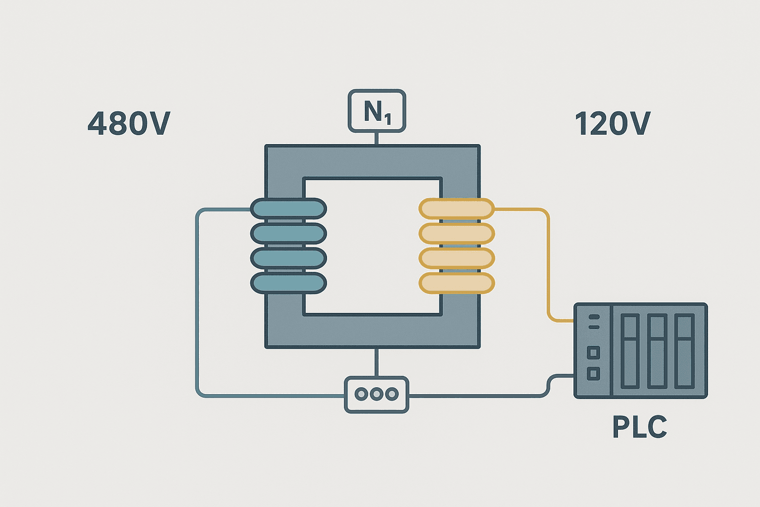
If you've spent any time in a control panel, you've touched a control transformer. That block of iron and copper sitting between your 480V supply and your 120V or 24V control circuit is doing quiet, reliable work every second the machine runs. But a surprising number of engineers treat it as a black box: wire the primary, wire the secondary, done. When you understand what's actually happening inside, sizing and wiring decisions become a lot more straightforward, and troubleshooting a dead control circuit gets faster.
What Is an Electrical Transformer and How Does It Work?
An electrical transformer is a static device that transfers electrical energy between two or more circuits through electromagnetic induction, with no moving parts and no direct electrical connection between primary and secondary. It steps voltage up or down in proportion to the ratio of turns in its two windings, while keeping volt-amperes (VA) nearly constant. Transformers only work with AC because they rely on a continuously changing magnetic flux in the core to induce voltage in the secondary winding.
The Physics in Plain Terms
The primary winding is connected to the AC supply. As the AC cycles, current flows back and forth through the primary, creating a magnetic field that grows, collapses and reverses direction at line frequency (50 Hz or 60 Hz). That changing magnetic field passes through the laminated iron core and links directly to the secondary winding. Faraday's law says a changing flux induces a voltage proportional to the number of turns it threads through. More turns on the secondary means higher induced voltage. Fewer turns means lower voltage.
The iron core is laminated, meaning it's built from thin sheets of silicon steel pressed together. Laminations break up eddy currents that would otherwise circulate through a solid iron core and waste energy as heat. A well-designed transformer at full load is typically 97-99% efficient. That's why they run warm but not hot under normal conditions.
The Turns Ratio: The Key Relationship
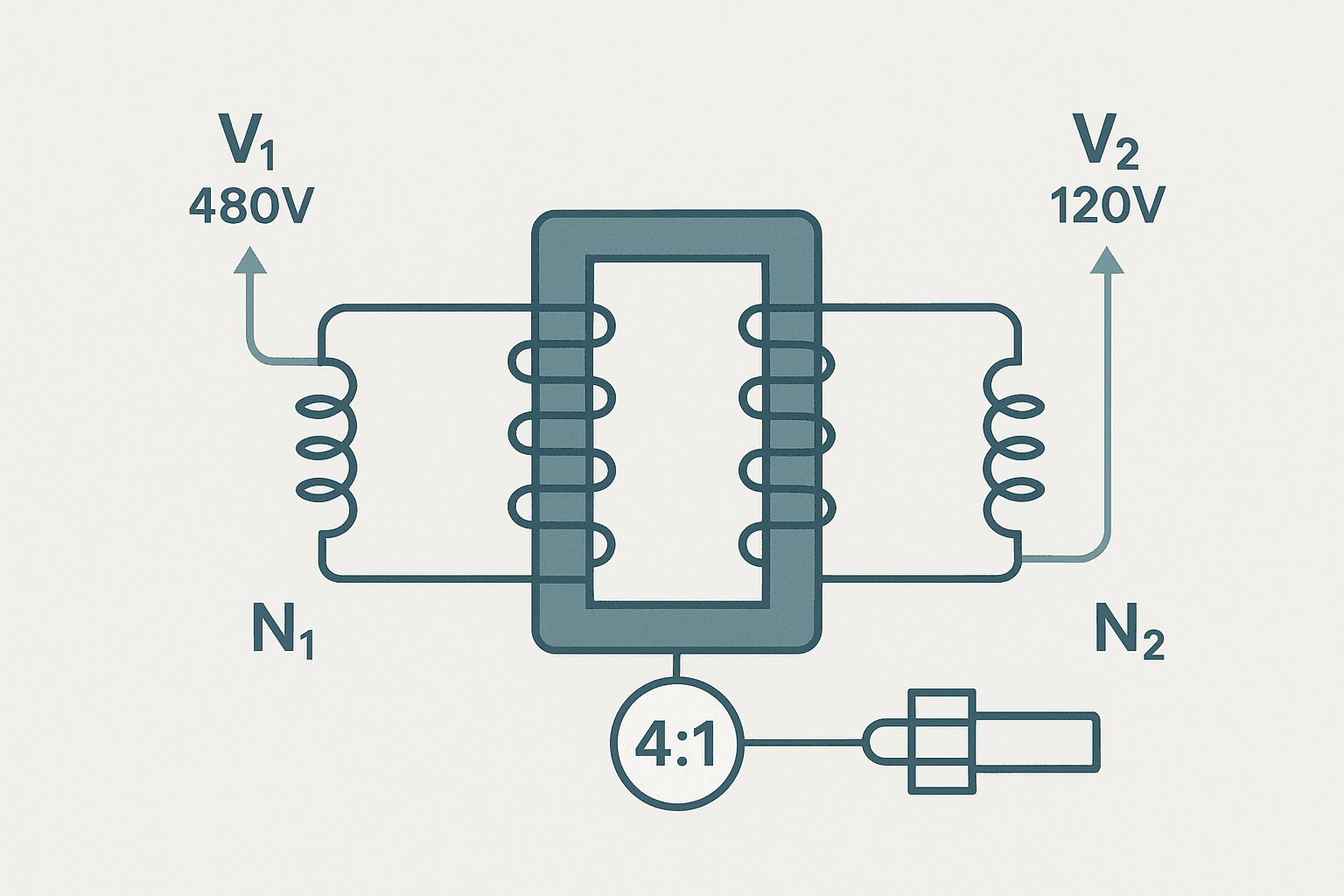
The turns ratio (N1:N2) relates directly to the voltage ratio (V1:V2) and inversely to the current ratio (I1:I2). These three relationships come from the same conservation of energy:
- Voltage ratio: V1 / V2 = N1 / N2
- Current ratio: I1 / I2 = N2 / N1 (inverse of voltage ratio)
- Power balance: V1 x I1 = V2 x I2 (ignoring losses)
A concrete example: a 480V to 120V step-down transformer has a turns ratio of 4:1. If the secondary delivers 2 A at 120V (240 VA), the primary draws 0.5 A at 480V. The VA is the same on both sides. This is why control transformers are rated in VA, not watts. Loads on the secondary can be resistive (heaters, pilot lights), inductive (relay coils, solenoids) or a mix, and VA accounts for all of them.
Types of Transformer You'll See in Automation
| Type | Typical Use | Primary Voltage | Secondary Voltage |
|---|---|---|---|
| Control transformer | Panel control circuit supply | 240V or 480V | 120V or 24V |
| Machine tool transformer | Larger panel loads, lighting | 480V | 120V or 240V |
| Isolation transformer | Noise isolation, medical, test | 120V or 240V | 120V or 240V |
| Autotransformer | VFD soft-start, buck-boost | Varies | Varies |
| Distribution transformer | Utility step-down to plant | 4160V to 13.8 kV | 208V to 480V |
For most PLC panel work, you're dealing with control transformers in the 50 VA to 1000 VA range. These are purpose-built for the inductive loads typical of control circuits: relay coils, solenoid valves and motor starters. They have higher leakage reactance than general-purpose transformers, which limits fault current and helps them survive the brief short-circuit conditions that happen when large contactors close. That's a deliberate design feature, not a flaw.
Sizing a Control Transformer: Real Numbers
The most common mistake I see is undersizing because engineers only look at steady-state current. Relay coils and solenoids have an inrush current at energisation that can be 6 to 10 times their sealed current. If you're energising several solenoid valves simultaneously (think a pneumatic solenoid valve bank at machine start), the inrush VA spike can trip your primary fuse or drag the secondary voltage down far enough to cause relay chatter.
Here's the sizing process I use on every panel:
- List every load on the secondary: PLC power supply, I/O module current, relay coils, solenoid valves, pilot lights, HMI power supply if it runs from the transformer.
- For each inductive load, note both the sealed VA (steady state) and the inrush VA from the data sheet. If you don't have inrush data, use 6x sealed VA as a conservative estimate.
- Assume the worst case simultaneous inrush: all loads energised at once.
- Sum the sealed VA of all loads, then add the inrush of the largest single load (or largest group that energises together).
- Multiply that total by 1.25 and pick the next standard size up.
Transformer Terminal Markings and Wiring
Control transformers follow NEMA and IEC naming conventions for their terminals. In North America you'll almost always see H and X designations. H1/H2/H3/H4 are primary (high voltage) terminals. X1/X2/X3 are secondary (low voltage) terminals. The number of H terminals tells you how many primary voltage configurations are available.
Wiring a Dual-Voltage Primary (240V / 480V)
Most control transformers in North America have a dual-voltage primary so one part number covers both 240V and 480V sites. The primary has two coil sections. Wire them in series for 480V, in parallel for 240V.
- 480V connection: link H2 to H3, apply line voltage across H1 and H4.
- 240V connection: link H1 to H3 and H2 to H4, apply line voltage across H1-H2 (or H3-H4, they're the same node).
- Secondary: X1 and X2 for 120V, or X1 to X3 midpoint for 60V if a center tap exists.
Grounding the Secondary
NEC Article 250 and Article 450 require that transformer secondary circuits operating at 50V to 1000V be grounded if certain conditions apply. For a standard 120V control circuit, X2 is grounded to the panel ground bus. This creates a grounded conductor (neutral) on the secondary and limits the voltage to ground on the ungrounded conductor (X1) to 120V. It also lets overcurrent devices operate correctly on a ground fault. If you're running an ungrounded 120V control circuit intentionally (for ground-fault monitoring), that's a deliberate engineering choice, not an accident.
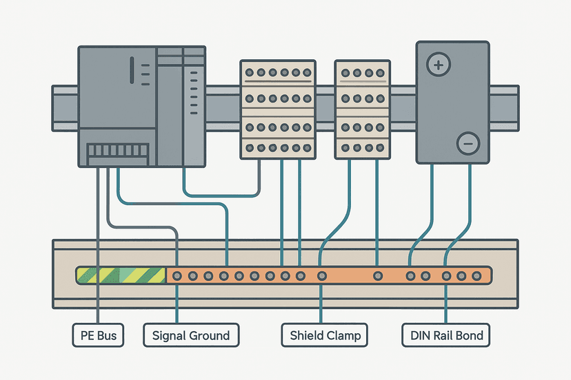
Correct panel grounding practice flows all the way from the transformer secondary through every circuit. The post on control panel grounding techniques covers the full panel ground hierarchy if you want to go deeper.
Fusing Primary and Secondary
NEC 450.3 sets the rules. For a control transformer under 1000 VA with a primary over 9A, fuse the primary at no more than 125% of rated primary current. For the secondary, fuse at no more than 125% of rated secondary current. Use time-delay (slow-blow) fuses on the secondary to handle the inrush of relay coils and solenoids without nuisance blowing. Class CC or KTK fuses in the 2A to 15A range cover most control transformer secondaries.
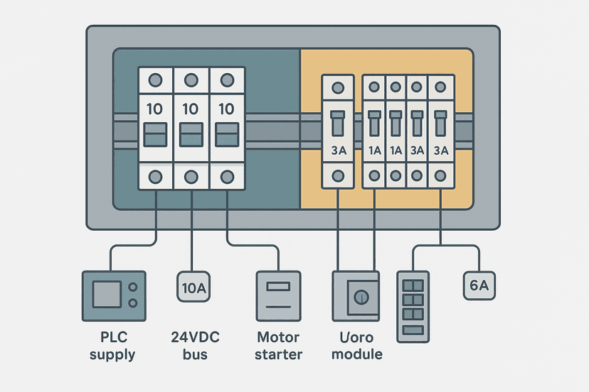
The fuse vs breaker selection guide has more detail on choosing between fuses and miniature circuit breakers for control circuit protection, including the pros and cons of each for this exact application.
Practical Wiring Tips From the Field
- Run primary and secondary wiring in separate conduit or at least separate wire bundles. Transformer secondaries at 120V are low enough to be treated as control wiring, but keeping them away from high-voltage primary conductors reduces noise coupling.
- Label the transformer clearly: primary voltage, secondary voltage, VA rating and the tap link configuration. The next engineer who opens the panel will thank you.
- Use a ferrite core or line reactor on the primary if the transformer feeds a PLC panel that also has a VFD. VFDs generate high-frequency switching noise that can couple back through a shared supply. See the post on control panel wire routing and segregation for practical segregation rules.
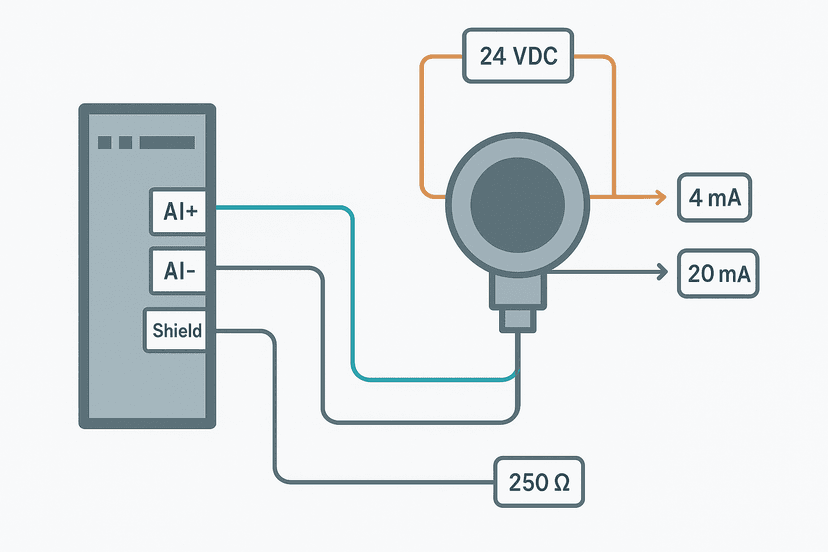
- If you're wiring 4-20 mA signal loops that are powered by a 24V rail derived from the transformer, make sure the signal common is correctly referenced. Signal grounding errors on analog loops are a common source of noise. The PLC analog input wiring guide covers this well.
- Torque the H and X terminal screws. These terminals carry current continuously. Loose connections generate heat and cause intermittent voltage sag on the secondary, which shows up as unexplained relay chatter or PLC brownout faults.
How Transformer Faults Show Up in a PLC System
A failing or undersized control transformer usually announces itself in one of three ways. First, relay coils chatter on machine start when multiple solenoids energise simultaneously, which means the secondary voltage is sagging below the relay's drop-out voltage. Second, the primary fuse blows repeatedly, which means you're either undersized for the inrush load or you have a fault on the secondary. Third, the transformer runs hot enough to discolour its insulation or smell, which means it's working harder than it should be.
A PLC CPU fault or unexpected I/O module reset that clears when the machine is lightly loaded but repeats under full load is often a power supply issue tracing back to a secondary voltage sag from an overloaded transformer. Before you dig into PLC diagnostics, measure the secondary voltage under full load. If it's more than 10% below nameplate, the transformer is the problem. The guide on PLC CPU fault diagnosis lists this as one of the first physical checks to make.
For analog signal quality, a noisy or sagging transformer secondary feeds directly into the noise floor of your 4-20 mA loops and the scaling accuracy of your PLC analog inputs. The 4-20 mA scaling formula guide assumes a clean, stable supply. If your supply is unstable, scaling math won't save you.
Quick Reference: Transformer Sizing and Wiring Checklist
- Calculate total steady-state VA of all secondary loads.
- Identify the highest inrush load and add its inrush VA.
- Multiply total by 1.25 and select the next standard VA size.
- Verify primary tap configuration matches site supply voltage.
- Fuse primary at 125% of rated primary current (time-delay).
- Fuse secondary at 125% of rated secondary current (time-delay).
- Ground X2 to panel ground bus per NEC 250 (for grounded systems).
- Torque all H and X terminal screws to the manufacturer's specification.
- Measure secondary voltage under full load and confirm it stays within 10% of nameplate.
Related Reading
- VFD Fault Codes: What They Mean and How to Fix Them
- 3-Wire Sensor Wiring: PNP vs NPN to PLC Inputs
- Pneumatic Solenoid Valves: Types, Wiring and PLC Control
Keep Learning
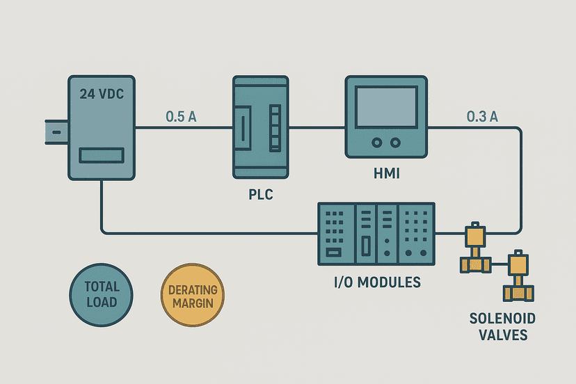
Transformer basics connect directly to how you size and protect the rest of your control panel. The 24 VDC power supply sizing guide picks up where this post leaves off, covering SMPS selection for PLC I/O rails. For the full picture on protecting your control circuits, read the fuse vs breaker selection post and the control panel grounding guide.
Frequently asked questions
What is the basic principle of a transformer?
How do you calculate a transformer turns ratio?
What VA rating do I need for a control transformer?
Why does a transformer only work with AC and not DC?
What is the difference between H1/H2 and X1/X2 terminals on a control transformer?
How do you wire a 480V to 120V control transformer?
Can you run two loads in parallel on a transformer secondary?
What happens if a transformer is oversized or undersized?
Do I need to fuse a control transformer secondary?
What is a multi-tap transformer and when do you use one?
Learn this by building it
There is a PLC in this site. It runs a real scan engine, checks your logic against the same tests a working machine would fail, and needs no download and no account.
Open the exercisesFree, no signup, runs in your browser. See all 16 exercises.
Was this helpful?