Contactor vs Motor Starter vs Relay: Key Differences
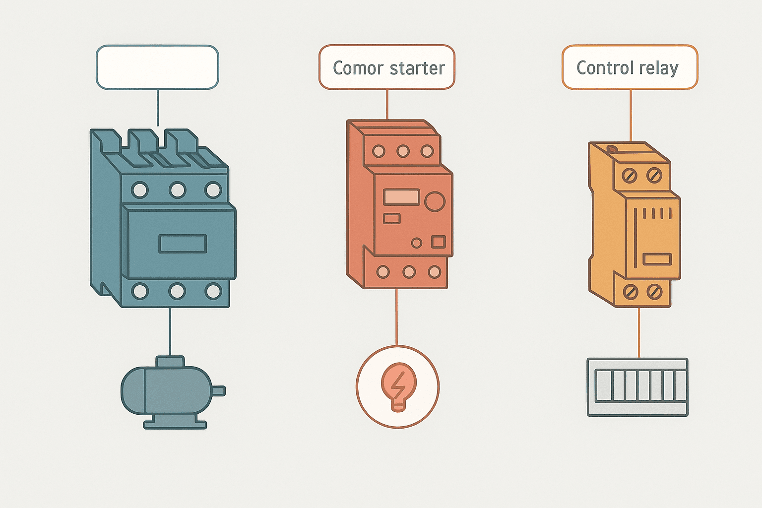
Walk into any MCC room and you will see all three: chunky three-pole contactors bolted to back-plates, motor starters with their overload blocks clipped on underneath, and rows of plug-in control relays on DIN rail. They all switch electrical circuits, they all have coils and contacts, and they are all regularly confused with each other on panel drawings and purchase orders. The difference matters because picking the wrong one causes nuisance trips at best and welded contacts or a motor fire at worst.
What Is the Difference Between a Contactor, Motor Starter and Control Relay?
A control relay is a small plug-in device rated for pilot-duty currents up to about 10 A, used to switch low-power control signals. A contactor is a heavy-duty switching device built to make and break high-current power circuits, especially inductive motor loads, using arc suppression hardware. A motor starter is a contactor with a thermal or electronic overload relay factory-assembled into one unit, providing both switching and sustained-overcurrent protection for motors. The relay controls; the contactor powers; the motor starter protects.
Control Relays: What They Are Actually For
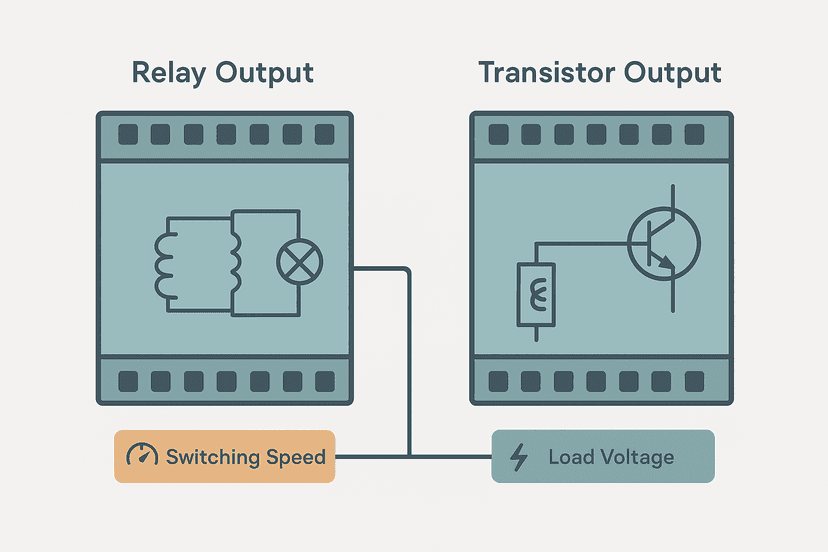
A control relay does one thing well: it electrically isolates a low-energy control signal from a slightly higher-energy pilot circuit, or multiplies one signal into several contact copies. In a PLC panel you will find them sitting between PLC output modules and field devices that would otherwise exceed the output module's current rating. A typical transistor output module is rated 0.5 A per point; a 24 VDC relay coil draws around 50 mA, so the relay does the heavy lifting.
The contacts on a control relay are small silver-alloy discs inside a plastic housing, with no arc chute and no blow-out magnet. That is fine for switching 120 VAC at 2 A to a pilot light or an annunciator. It is not fine for switching a 7.5 kW motor. The inrush alone would arc the contacts, and within a few hundred operations they weld shut. I have seen this happen on a commissioning where someone grabbed a relay out of the spares kit instead of a contactor because both were 24 VDC coil devices sitting in the same bin. The motor ran for three days before the contacts fused. Relay vs transistor output decisions follow a similar logic when you are choosing PLC output types.
Contactors: Built for Inductive Power Switching
A contactor is purpose-built to make and break high-current inductive loads thousands of times over its service life. The key differences from a relay are physical: contactors have arc chutes (ceramic or fibre chambers that cool and extinguish the arc as the contacts open), silver-cadmium oxide or silver-tin oxide contact tips thick enough to erode over many operations without failure, and a laminated AC magnet with a shading ring to prevent buzzing on 50/60 Hz supply. Three-phase contactors have three main poles plus one or two auxiliary contacts for control feedback.
IEC 60947-4-1 defines utilization categories that tell you what a contactor is designed to switch. AC-3 is the rating you want for squirrel-cage motors: it means the device is tested to close onto full inrush current (typically six to eight times FLA) and open at full-load running current. AC-1 covers resistive and mildly inductive loads. AC-4 covers plugging and inching (jogging), which is harsher than AC-3 and requires a contactor derated by roughly 50%. Always check the category, not just the ampere number.
| IEC Category | Typical Application | Switching Duty |
|---|---|---|
| AC-1 | Resistive / slightly inductive loads | Make and break at rated current |
| AC-3 | Squirrel-cage motor starting | Close on inrush, open at FLA |
| AC-4 | Plugging, inching, reversing | Close on inrush, open on inrush |
| AC-6b | Capacitor bank switching | High inrush, leading PF |
| DC-3 | Shunt motor, resistive DC loads | Moderate inductive DC switching |
Coil voltage is a separate decision from contact rating. Most modern panels use 24 VDC coils driven directly from a PLC output or safety relay. The coil is just a solenoid; the contact rating is what matters for the load side. You can have a 24 VDC coil contactor switching a 400 VAC three-phase motor without any conflict. When wiring contactors in safety circuits, keep in mind the guidance in emergency stop circuit wiring for correct category compliance.
Motor Starters: Contactor Plus Overload in One Assembly
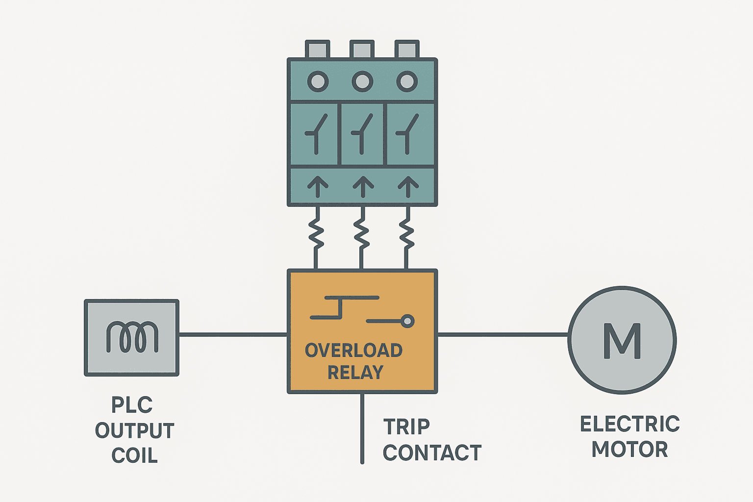
A motor starter adds an overload relay to the contactor. The overload relay sits in series with the motor supply, senses current continuously, and trips the normally-closed contact in the contactor control circuit when it detects sustained overcurrent. This interrupts the coil circuit and drops out the contactor, cutting power to the motor before the windings overheat. NEC Article 430 requires motor overload protection in virtually every installation, so a bare contactor is not a compliant motor starter.
Thermal overload relays use bimetal strips: current heats the strip, the strip bends, and it trips a mechanism after a time-current curve. They are cheap, reliable and self-resetting or manual-reset. Electronic overload relays use current transformers clamped around the motor leads and a microprocessor to calculate thermal capacity. They add phase-loss detection, ground fault sensing, a 4-20 mA current output you can wire to a PLC analog input, and remote reset capability. For critical pumps or compressors the electronic version is worth the extra cost.
Setting the overload correctly is critical. The dial on a thermal overload relay sets the full-load amp trip threshold. Set it exactly to the motor nameplate FLA, not higher. People round up because they are nervous about nuisance trips, but a relay set 20% high may never trip in time to save the windings. If you are seeing genuine nuisance trips, check for a supply voltage issue or a mechanical problem with the driven load rather than bumping the overload setting. On variable-speed drives the situation is different: the drive's own electronic overload usually handles motor protection, so the external starter's overload may be bypassed or removed. Check VFD parameters for the motor protection settings built into the drive.
Side-by-Side Comparison: Ratings and Construction
| Feature | Control Relay | Contactor | Motor Starter |
|---|---|---|---|
| Typical current rating | Up to 10 A (pilot duty) | 9 A to 1000+ A (AC-3) | Same as contactor + OLR |
| Arc suppression | None | Arc chutes, blow-out magnets | Arc chutes (in contactor section) |
| Overload protection | None | None | Yes, thermal or electronic OLR |
| Mounting | DIN rail plug-in socket | DIN rail or screw mount | DIN rail or panel mount |
| Coil voltages | 5-240 VAC/VDC | 24 VDC to 480 VAC | Same as contactor |
| Primary use | Pilot duty, PLC I/O interface | Motor and power switching | Complete motor starting and protection |
How the PLC Fits Into All of This
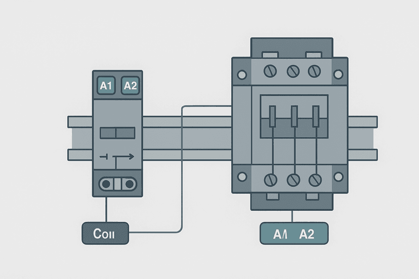
In a typical PLC-controlled motor circuit the wiring goes: PLC digital output energizes a control relay coil (if the output module current is limited), the relay contact closes to energize the contactor coil, the contactor main contacts close to power the motor, and the contactor's auxiliary contact feeds back to a PLC digital input so the program can verify the motor actually started. The overload relay's trip contact is wired in series with the contactor coil circuit, or its auxiliary contact feeds a separate PLC input for a fault alarm. Understanding PLC output wiring types helps you decide whether you need that intermediate relay at all.
Some modern electronic overload relays connect directly to IO-Link or a fieldbus network, letting the PLC read motor current, thermal capacity used and trip cause without extra analog wiring. If you are specifying a new panel, that capability is worth considering. You can read more about how IO-Link extends sensor and device data to the controller in IO-Link explained.
Motor Starter Run Permissive with Overload Fault Latch (Studio 5000). Ladder logic (7 rungs): Rung 0: examine if Sys_Ready is on (XIC), then examine if HMI_MotorStart is on (XIC), then examine if HMI_MotorStop is off (XIO), then examine if OLR_Tripped is off (XIO), then examine if Motor_FaultLatch is off (XIO), then latch output Motor_Cmd (OTL). Rung 1: examine if HMI_MotorStop is on (XIC), then unlatch output Motor_Cmd (OTU). Rung 2: examine if Motor_Cmd is on (XIC), then energize output KM1_Coil_Out (OTE). Rung 3: examine if KM1_Coil_Out is on (XIC), then examine if KM1_AuxFB is off (XIO), then TON on Motor_StartTimeout. Rung 4: examine if Motor_StartTimeout.DN is on (XIC), then examine if KM1_AuxFB is off (XIO), then examine if Motor_NoFB_OS is on (XIC), then latch output Motor_FaultLatch (OTL). Rung 5: examine if OLR_Tripped is on (XIC), then examine if OLR_Trip_OS is on (XIC), then latch output Motor_FaultLatch (OTL). Rung 6: examine if Motor_FaultLatch is on (XIC), then examine if HMI_FaultAck is on (XIC), then examine if OLR_Tripped is off (XIO), then unlatch output Motor_FaultLatch (OTU). KM1_Coil_Out energizes the contactor coil. KM1_AuxFB is the contactor auxiliary feedback contact wired to a PLC input. OLR_Tripped is the overload relay trip contact wired to a separate PLC input. The logic latches a fault if the contactor does not confirm within 4 seconds or if the overload trips, and requires operator acknowledge to clear.
When to Use Each One: Quick Decision Guide
- Control relay: switching PLC output signals, isolating 24 VDC from 120 VAC pilot circuits, multiplying one output into multiple contact copies, or driving a contactor coil from a module with limited current drive.
- Contactor: switching three-phase or single-phase power loads where you supply your own separate overload protection (for example a VFD already has motor protection built in, or you are switching a resistive heater bank).
- Motor starter: any direct-on-line or star-delta motor application where the motor needs both switching and thermal overload protection in one compliant assembly. This is the default choice for direct motor starting.
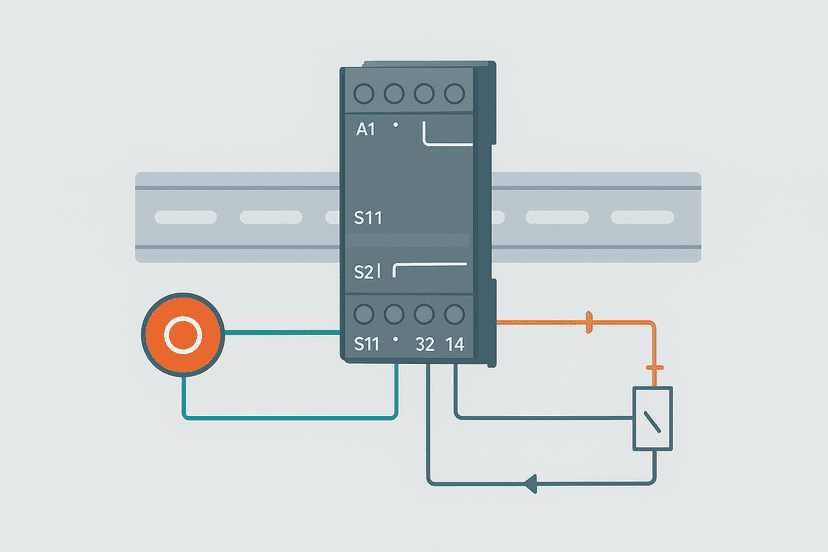
- Safety relay: when the circuit must achieve a functional safety level (PLd or SIL 2) and you need force-guided contacts and cross-monitoring. See safety relay wiring explained for the detail.
One question that comes up often: can a contactor substitute for a circuit breaker? No. A contactor has no short-circuit interrupting rating (SCCR) worth speaking of. It is designed to break load current, not fault current. You always need a properly rated fuse or breaker upstream. Fuse vs breaker selection covers how to size that upstream protection correctly.
For panels with multiple motor starters, proper control panel wire routing between the high-current contactor wiring and the low-level PLC I/O wiring prevents noise pickup that can cause spurious input faults. Keep power wiring and signal wiring in separate cable ducts, and connect your control panel grounding to a single star point.
Keep Learning
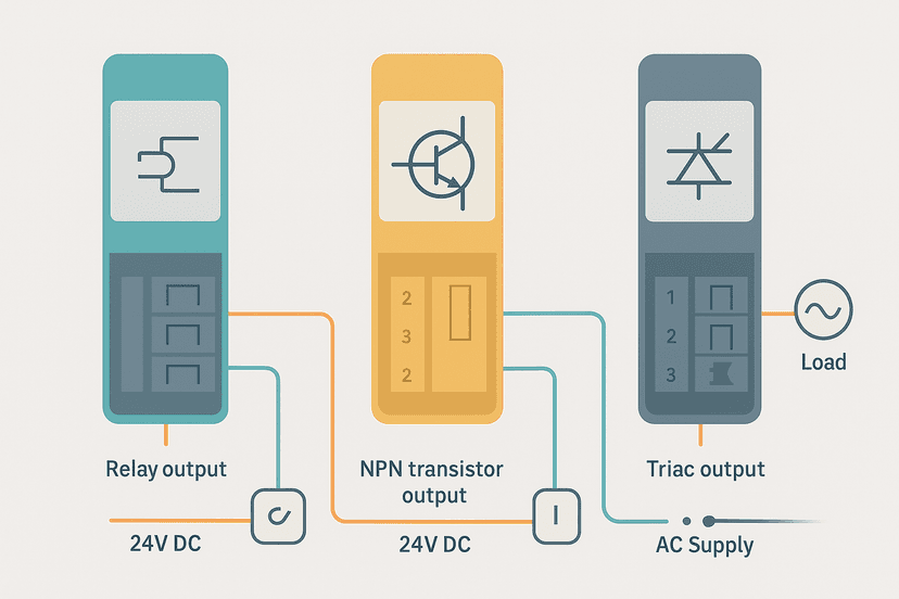
Now that you know which device belongs where, the next step is understanding how the PLC output side connects to each of them. PLC output wiring: relay, transistor and triac walks through every output type and the loads each can drive. If you are building a star-delta starter circuit in ladder logic, try the star-delta motor starter exercise in the interactive ladder editor to wire up the timing sequence yourself. And if you want to see how the overload feedback integrates into a full motor control program, the 3-motor start sequence exercise shows the run-confirm fault pattern in a real multi-motor application.
Frequently asked questions
What is the difference between a contactor and a motor starter?
Can I use a control relay instead of a contactor to switch a motor?
What is the difference between a relay and a contactor in terms of physical construction?
How do I size a contactor for a motor?
What does AC-3 mean on a contactor?
Does a motor starter replace a circuit breaker?
What is a control relay used for in a PLC panel?
Can a contactor be used without an overload relay?
What is the difference between a thermal overload relay and an electronic overload relay?
Why does a contactor hum or chatter in service?
Learn this by building it
There is a PLC in this site. It runs a real scan engine, checks your logic against the same tests a working machine would fail, and needs no download and no account.
Open the exercisesFree, no signup, runs in your browser. See all 16 exercises.
Was this helpful?