Relay Logic vs PLC Logic: Key Differences Explained
Relay logic ran factories for decades before the first PLC shipped in 1969. A lot of it is still running today. So the question is not 'relays are old, PLCs are new'. The real question is: what actually changes when you replace a relay panel with a PLC, and when does that change genuinely pay off?
What Is Relay Logic vs PLC Logic?
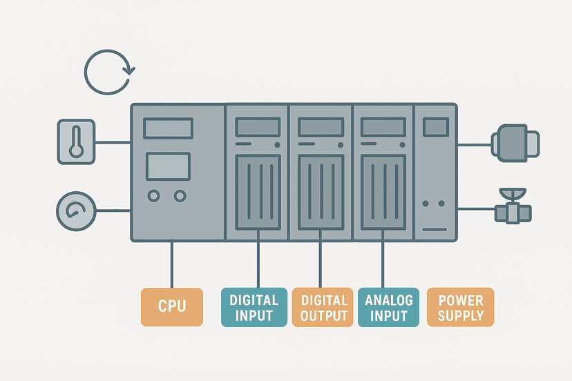
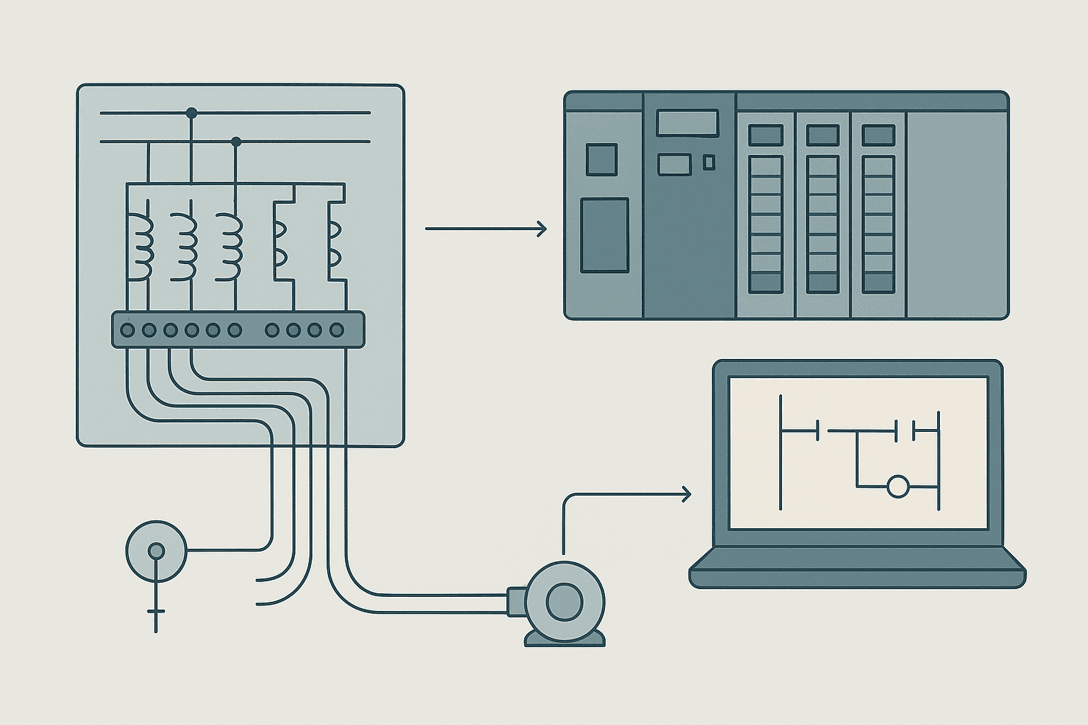
Relay logic is a hardwired control method where physical relay coils and contacts are wired together on a panel to implement Boolean control functions. When current flows through a coil it pulls in an armature, closing or opening contacts elsewhere in the circuit. The logic lives entirely in the wiring. Change the logic and you change the wires. PLC logic stores the same control function as a program, typically written in ladder logic (which deliberately mimics relay ladder diagrams) or another IEC 61131-3 language. The CPU executes that program repeatedly in a scan cycle, reading physical inputs, evaluating logic, and writing physical outputs. The field wiring connects to I/O modules and stays the same even when you rewrite the program.
How Relay Logic Works: The Physical Side
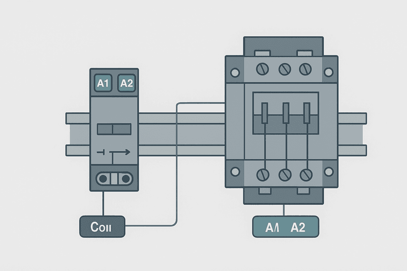
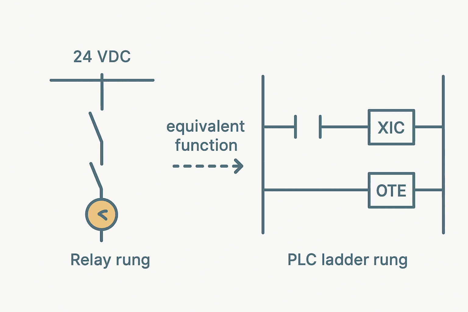
A classic relay panel has rows of DIN-rail-mounted relays, each with a coil terminal and a set of contacts. Wire a pushbutton in series with coil K1, and when you press the button K1 picks up. Wire K1's normally open (NO) contact in series with K2's coil, and now K2 follows K1. That is relay logic: AND gates are series contacts, OR gates are parallel contacts, memory is a seal-in (a contact from the coil's own output wired in parallel with the start button). You can read more about how those contact types translate into PLC programming in the article on NO vs NC contacts in PLC ladder logic. The logic is identical; only the medium changes.
How PLC Logic Works: Scan Cycle Execution
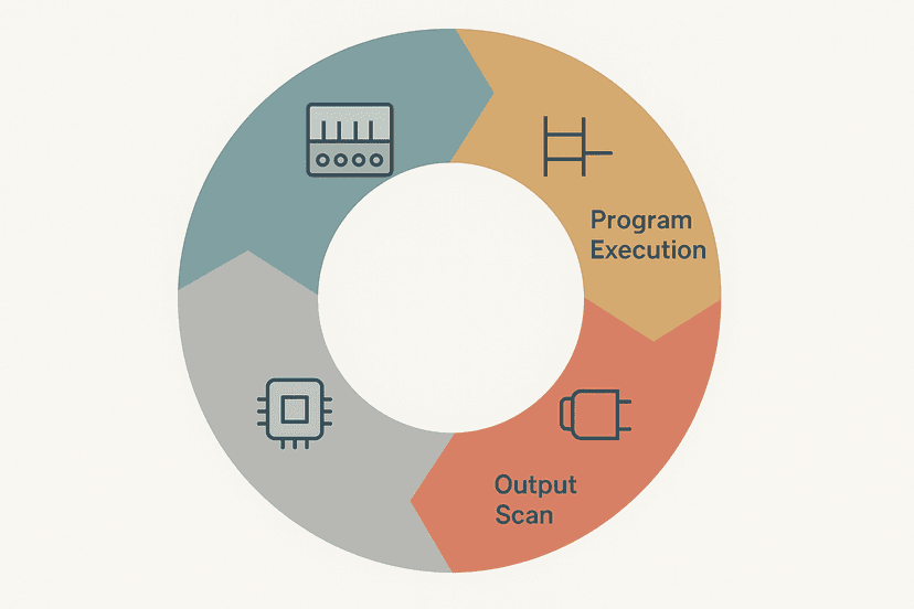
A PLC reads all physical inputs into an image table at the start of each scan, executes the program rung by rung using those stored values, then writes the output image back to the physical output terminals. The whole cycle repeats every 1 to 20 ms on a typical machine-control PLC. Understanding this scan behaviour is important because it is where PLC logic and relay logic diverge in subtle ways, particularly around rung-to-rung interactions. The article on how the PLC scan cycle works covers that in detail. Because the logic is software, adding a new condition means inserting a contact instruction on an existing rung, not pulling wire. Removing a condition means deleting an instruction. On a relay panel the same change involves cutting wire, adding terminals, buying relays and updating a drawing.
Side-by-Side Comparison: 8 Factors That Matter
| Factor | Relay Panel | PLC |
|---|---|---|
| Wiring volume | High: every logic change means rewiring | Low: field wiring is fixed; logic changes are software |
| Flexibility | Very low: modifications require rewire and redraw | High: program edits take minutes, even online |
| Fault finding | Multimeter and drawings; trace voltage contact by contact | Online monitoring shows all coil/contact states live |
| Scan speed | Near-instantaneous parallel operation | 1 to 20 ms scan cycle; fast enough for most machines |
| Contact availability | Limited to physical contacts per relay (typically 2 to 4) | Unlimited software contacts on any internal bit |
| Upfront cost (small panel) | Lower: relays are cheap, no PLC needed | Higher: CPU + I/O modules add cost below ~20 I/O |
| Long-term modification cost | High: labour and materials for every change | Low: engineer-hours only, no extra hardware |
| Wear and maintenance | Relay contacts wear (1M to 10M ops); need replacement | CPU and solid-state I/O have no mechanical wear |
The Ladder Logic Connection: Why They Look the Same
When Modicon developed the first PLC, the goal was to let relay engineers program it without retraining. So ladder logic uses the same visual language: vertical power rails, horizontal rungs, contact symbols that look like relay contacts, and coil symbols that look like relay coils. An XIC (Examine If Closed) contact in Studio 5000 is the software equivalent of a normally open relay contact. An XIO (Examine If Open) mirrors a normally closed contact. You can see exactly how those two instructions differ in the XIC vs XIO article. The big functional difference is that a PLC coil bit can appear as a contact on every other rung in the program simultaneously, with no physical relay needed. A real relay has 2 to 4 contact sets. An internal PLC bit has unlimited contacts. That alone simplifies panel wiring enormously on machines with more than a handful of interlocks.
Fault-Finding: Where the Gap Is Biggest
This is where I have seen the biggest practical difference on the plant floor. On a relay panel with 40 relays and a wiring fault, you are tracing voltage with a multimeter through a drawing that may not match what was actually built. I have spent three hours on a relay panel chasing an intermittent weld on a contact that would only drop out when the panel warmed up. On a PLC, you connect a laptop, go online, and every contact and coil in the program shows its real-time state highlighted in the software. A stuck input shows up as a contact that never changes state. A failed output is a coil that energises in software but produces no voltage at the terminal. The article on PLC troubleshooting with online monitoring walks through exactly that process. For the multimeter side of things, PLC I/O fault diagnosis with a multimeter covers what to measure when the software is not enough.
When Relays Still Win
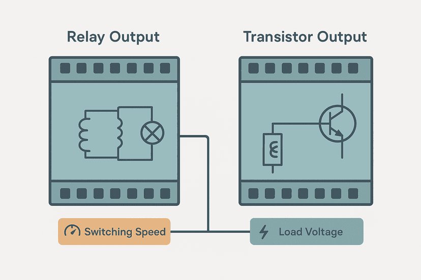
Relay panels are not obsolete. There are real situations where they are the right answer: Very simple machines. A conveyor with two pushbuttons and one motor does not need a PLC. Three relays, a terminal block and a fuse block is faster to build, easier to document and cheaper to maintain. Galvanic isolation. A relay contact provides genuine galvanic isolation between the control circuit and the load circuit. If you are switching an AC field device from a 24 VDC PLC, a relay output module (which contains real relay contacts) or an interposing relay gives you that isolation. A transistor output does not. Safety loops. E-stop circuits and guard-door loops under ISO 13849-1 typically use hardwired forced-guided safety relays or dedicated safety PLCs, not a standard PLC output. The reason is that a PLC CPU fault can leave an output in any state. A forced-guided relay fails to a known de-energised position. The article on emergency stop circuit wiring categories explains how those architectures work. Remote locations. If a machine lives in a remote pumping station and the maintenance crew are electricians rather than PLC technicians, a relay panel with a good drawing is sometimes easier to keep running than a PLC with obsolete firmware that nobody on site can support.
Retrofitting Relay Panels to PLCs: What to Watch For
The biggest trap in a relay-to-PLC retrofit is assuming the relay logic drawing is correct. In my experience it never is, not after 20 years of maintenance changes. Before you write a single rung of PLC code, trace the actual wiring and verify each relay's function against the machine's real behaviour. Second trap: relay logic operates all rungs simultaneously and in parallel (it is a physical circuit). PLC logic is sequential and scans one rung at a time. On most machines this makes no practical difference. But if the relay panel uses feedback contacts from one relay to immediately influence another in the same power cycle, you may need to add one-shot (OSR) instructions or restructure rungs to replicate that behaviour correctly. The article on one-shot rising edge in ladder logic is useful here. Third: the relay panel's seal-in circuits become OTL/OTU latch coils or XIC self-seal contacts in the PLC program. Both approaches work. The OTL and OTU latch coils article compares them. For output wiring, the PLC output module type matters. If the relay panel switched 120 VAC loads you need relay output modules or interposing relays on the PLC outputs. Transistor outputs are DC only. The full breakdown is in PLC output wiring: relay, transistor and triac.
Relay Seal-In Equivalent: PLC Start/Hold/Stop with Interlock (Studio 5000). Ladder logic (4 rungs): Rung 0: examine if PB_Start is on (XIC), then examine if PB_Stop is off (XIO), then examine if OLR_Trip is off (XIO), then examine if Guard_Open is off (XIO), then latch output Motor_Held (OTL). Rung 1: examine if Motor_Held is on (XIC), then examine if PB_Stop is off (XIO), then examine if OLR_Trip is off (XIO), then examine if Guard_Open is off (XIO), then energize output Motor_Held (OTE). Rung 2: examine if PB_Stop is on (XIC), then unlatch output Motor_Held (OTU). Rung 3: examine if Motor_Held is on (XIC), then energize output KM1_Coil_Out (OTE). This four-rung block replicates the classic relay seal-in (hold-in) circuit in PLC ladder logic. Rung 1 sets the Motor_Held latch on a rising Start press, provided Stop, overload and guard-door interlocks are clear. Rung 2 holds the latch by self-sealing Motor_Held in series with the same safety interlocks, so any interlock opening drops the latch even without pressing Stop. Rung 3 is a dedicated OTU rung that unlatches cleanly on Stop. Rung 4 drives the physical contactor output. Separating the latch logic from the output coil is good practice: it lets you add more conditions to the hold rung later without touching the output rung.
The diagram above evaluates one scan. Run these exact rungs on a real scan cycle to watch the latching and the timers behave.
Run this in the simulatorNotice that this circuit uses OTL/OTU latching rather than a simple self-seal XIC contact. Either works, but the OTL approach makes the latching intent explicit in the code. You can practice the sealed-in coil concept yourself in the interactive sealed-in coil exercise and compare it to the set/reset exercise to see both methods side by side.
Cost Crossover: Where PLCs Start Paying Off
A rough rule that holds up in practice: below about 20 I/O points a relay panel is usually cheaper to build. Above 30 to 50 I/O points a PLC is almost always cheaper when you factor in wiring labour, not just hardware. Above that threshold the reduction in wire count, the ability to reuse I/O for multiple functions, and the diagnostic savings tip the balance decisively. For sizing the 24 VDC supply that will power either the relay coils or the PLC I/O modules, the 24 VDC power supply sizing guide gives the calculation method. For protecting individual circuits, the fuse vs breaker selection article covers when to use each device in the panel.
PLC Interlocks vs Hardwired Interlocks
One area where the two approaches are deliberately combined is machine safety. A PLC can implement operational interlocks (conveyor must be running before the pusher extends) very efficiently. But safety-rated interlocks, things that prevent injury, should generally be hardwired. A PLC CPU fault, a program bug or a firmware issue can put any output in any state. A hardwired safety relay or safety-rated PLC with a defined safe state is required for Category 3 and above under ISO 13849-1. The article on ladder logic interlocks covers operational interlocks in PLC code. For the safety side, safety relay wiring circuits and ISO 13849-1 PL levels are the right references.
Keep Learning
If you are moving from relay panels to PLC programming, the next step is understanding how the PLC represents inputs and outputs internally. Start with how PLC input and output modules work, then work through PLC internal bits, flags and coils to see how software bits replace the relay contacts you are used to. When you are ready to build and test ladder rungs without hardware, the free interactive ladder logic exercises let you toggle inputs and watch rung states in your browser exactly as you would in online monitoring.
Frequently asked questions
What is the main difference between relay logic and PLC logic?
Is ladder logic the same as relay logic?
Why is a PLC faster than a relay panel for complex logic?
When should you still use relays instead of a PLC?
Can a relay panel be more reliable than a PLC?
How do you troubleshoot a relay panel compared to a PLC?
Does replacing a relay panel with a PLC save money?
What is a relay coil equivalent in PLC ladder logic?
Do PLCs still use physical relays?
Can you mix relay logic and PLC logic in the same panel?
Now build it
You have just read about OTL and OTU and XIO. Reading a rung and making one behave are different skills, and the second one is the job.
State Coil / Fault Coil
Intermediateabout 15 minA fault lamp that latches ON when any alarm condition occurs, even briefly, and only clears on Reset. And if the condition is still present when Reset is released, the fault comes right back.
Build this rungFree, no signup, runs in your browser. See all 16 exercises.
Was this helpful?