Ladder Logic Interlocks: How They Work and Why
An interlock in ladder logic is the thing that stands between a valid command and a machine doing something catastrophic. It's a contact, or a chain of contacts, that blocks an output unless every precondition is satisfied. Simple idea. Huge consequences when you get it wrong.
What Is a Ladder Logic Interlock?
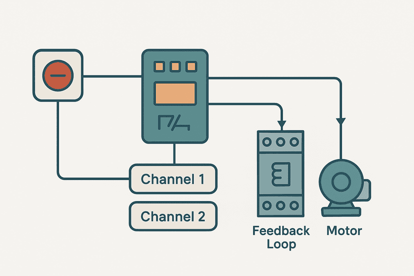
A ladder logic interlock is one or more contacts placed in series or parallel with an output coil to prevent energization unless defined conditions are met. Interlocks enforce valid machine states by blocking commands that would cause collisions, overloads, or unsafe operation. They can be implemented with physical wiring, PLC logic, or both, and they are the primary tool for preventing machine damage and protecting operators in standard (non-safety-rated) control systems.
Hardware vs Software Interlocks: Know the Difference
Before getting into ladder patterns, this distinction matters. A hardware interlock is wired in series with a load, a guard switch in series with a contactor coil for example, so the PLC program literally cannot energize the output regardless of what the code says. A software interlock lives entirely in ladder rungs and can be bypassed by a program change or a forced output.
For anything safety-rated (PLd, SIL 2 or above under ISO 13849-1 or IEC 62061), you need hardware safety circuits. Standard PLC interlocks handle operational protection, not functional safety. Keep the two in separate mental buckets. The emergency stop circuit wiring article goes deeper on the hardware side.
The Four Core Interlock Patterns
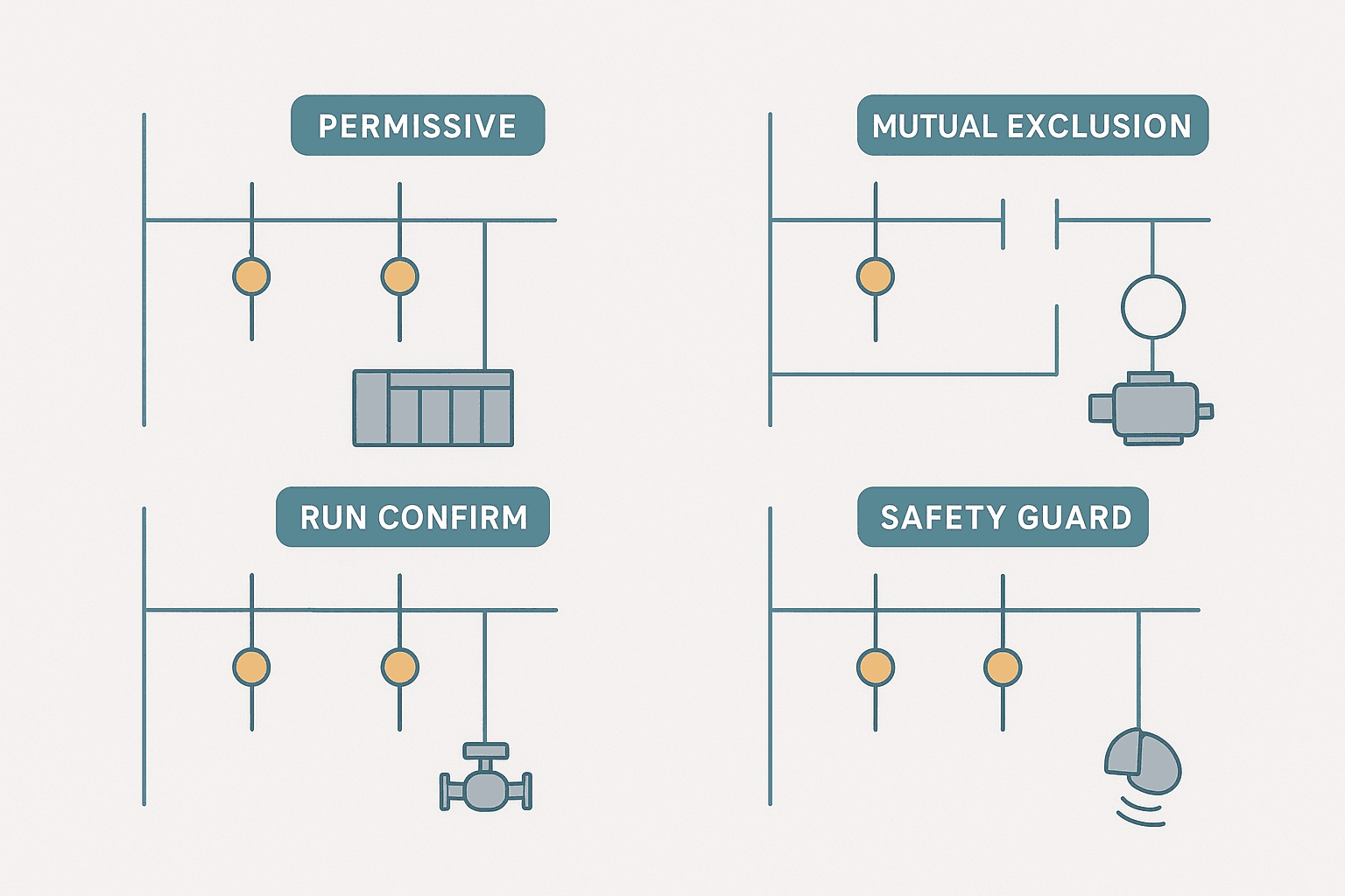
Almost every interlock you'll write in the field is a variation of one of these four patterns. Mix and match them, but understand each one first.
1. Permissive Interlock
A permissive is a list of conditions that must all be true before an output can energize. In ladder logic this means a series chain of XIC contacts before the output coil. Every contact is a gate; all gates must be open for current to flow.
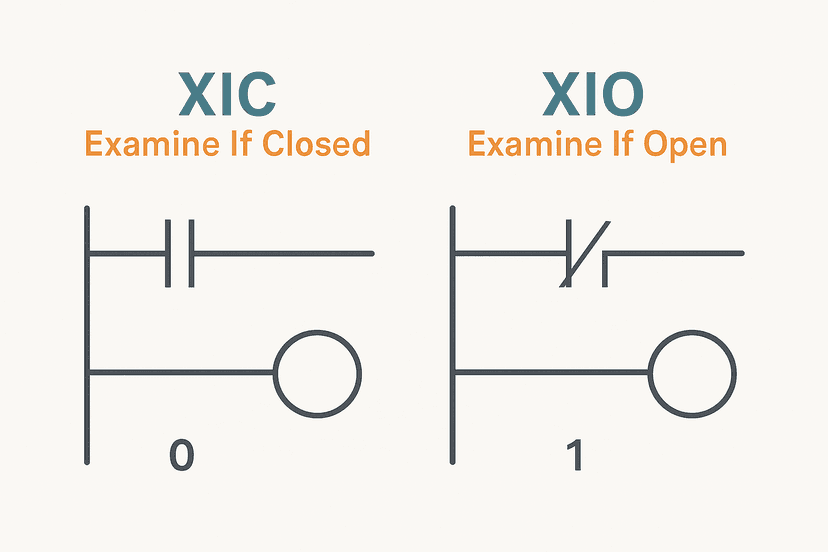
A conveyor might need: system enabled, no e-stop, no fault latch active, and a guard door confirmed closed. All four XIC contacts appear in series. Miss one and the conveyor stays off, no matter how hard the operator presses Start. The difference between XIC and XIO contacts is critical here: XIC passes power when the bit is true, XIO passes power when the bit is false. Mix them up and your permissive does the opposite of what you intend.
2. Mutual Exclusion Interlock
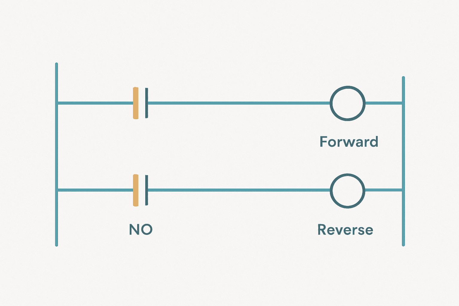
Mutual exclusion prevents two outputs that must never be on simultaneously from ever sharing that state. The textbook example is a forward/reverse motor starter: energizing both contactors at the same time shorts the supply phases together. The solution is an XIO contact of each output coil placed in series on the opposing rung.
Use XIO of the coil tag, not the physical input. The coil bit is written in the current scan; the input bit may be one scan old. That one-scan window is enough to destroy a contactor on a fast machine. I've seen it happen on a reversing conveyor drive where the programmer used the raw input bit for the interlock. Replaced two contactors before we found it.
3. Run-Confirm (Feedback) Interlock
Commanding a motor is not the same as running a motor. A run-confirm interlock verifies that the feedback signal, usually a VFD running status or a contactor auxiliary contact, arrives within a defined window after the command is issued. If it doesn't, a fault is latched and the command is removed.
This pattern catches tripped breakers, blown fuses, and failed contactors automatically. Without it you can run a machine for a whole shift believing a motor is running when it has been tripped out since the first cycle. When you're working with VFDs, the run-confirm signal often comes from the drive's digital output. The VFD fault codes guide explains the common feedback signals drives provide.
4. Sequential (State-Based) Interlock
A sequential interlock uses a step or state bit to gate outputs. Step 3 can only activate if Step 2 is complete. A hydraulic clamp can only extend if a part-present sensor is confirmed. This is the backbone of any sequential machine and it's how the PLC bottle filling machine project prevents a fill valve from opening before a bottle is seated.
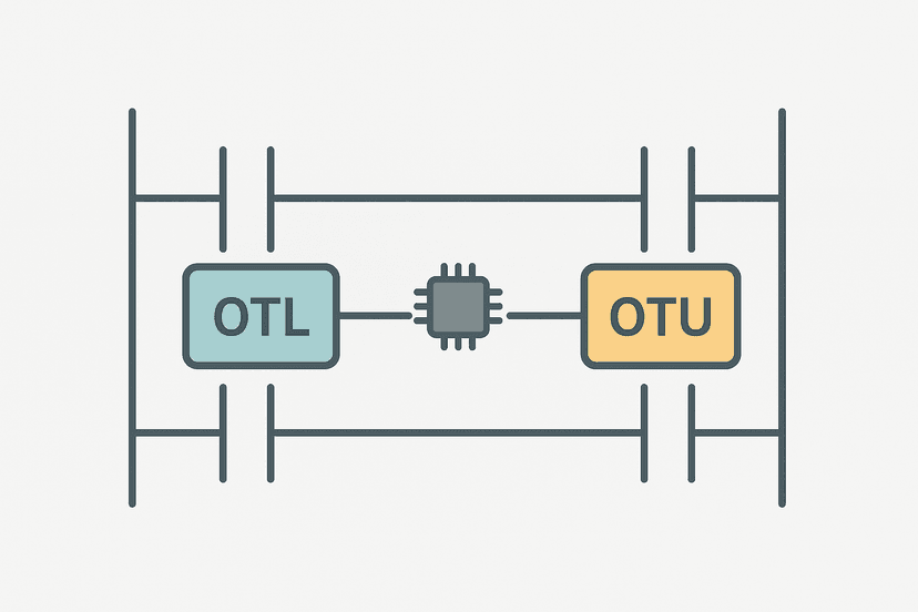
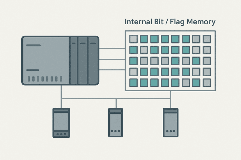
State bits work best as latched internal bits using OTL/OTU coils rather than OTE coils, because a latch holds its state across scans even if the condition that set it flickers. Pairing state bits with internal flag bits keeps the logic readable.
Interlock Pattern Comparison
| Pattern | What It Prevents | Key Contact Type | Typical Reset Method |
|---|---|---|---|
| Permissive | Premature or unsafe start | XIC (series chain) | Conditions clear automatically |
| Mutual Exclusion | Two conflicting outputs energizing together | XIO of opposing coil | N/A, always active |
| Run-Confirm | Undetected motor or valve failure | XIO of feedback bit + TON timeout | Operator acknowledge via HMI |
| Sequential | Out-of-order step activation | XIC of step/state bit | Step advances or resets via logic |
| Safety Guard (hardware) | PLC code bypass of critical function | Wired NC contact in series with load | Requires physical intervention |
Ladder Logic Interlock Example: Mixer with Lid and Direction Guard
Here's a fresh example that combines three of the four patterns. An industrial mixer has a lid safety switch, a forward and reverse agitator, and a run-confirm timeout. This is Rockwell Studio 5000 syntax, but the logic maps directly to any platform. Notice how the mutual exclusion XIO contacts use the coil tag names, not input addresses.
Mixer: Permissive Start, Mutual Exclusion Direction Guard, and Run-Confirm Fault. Ladder logic (9 rungs): Rung 0: examine if Sys_Enabled is on (XIC), then examine if Lid_Closed_SW is on (XIC), then examine if Mix_FaultLatch is off (XIO), then examine if HMI_FwdCmd is on (XIC), then examine if Mixer_Rev is off (XIO), then latch output Mixer_Fwd (OTL). Rung 1: examine if Sys_Enabled is on (XIC), then examine if Lid_Closed_SW is on (XIC), then examine if Mix_FaultLatch is off (XIO), then examine if HMI_RevCmd is on (XIC), then examine if Mixer_Fwd is off (XIO), then latch output Mixer_Rev (OTL). Rung 2: examine if HMI_StopCmd is on (XIC), then unlatch output Mixer_Fwd (OTU), then either unlatch output Mixer_Rev (OTU). Rung 3: examine if Mixer_Fwd is on (XIC), then energize output Mixer_Fwd_Out (OTE). Rung 4: examine if Mixer_Rev is on (XIC), then energize output Mixer_Rev_Out (OTE). Rung 5: examine if Mixer_Fwd is on (XIC), then examine if Mixer_RunFB is off (XIO), then TON on Mix_StartTimeout. Rung 6: examine if Mixer_Rev is on (XIC), then examine if Mixer_RunFB is off (XIO), then TON on Mix_StartTimeout. Rung 7: examine if Mix_StartTimeout.DN is on (XIC), then examine if Mixer_RunFB is off (XIO), then examine if Mix_Fault_OS is on (XIC), then latch output Mix_FaultLatch (OTL). Rung 8: examine if Mix_FaultLatch is on (XIC), then examine if HMI_FaultAck is on (XIC), then examine if Mixer_Fwd is off (XIO), then examine if Mixer_Rev is off (XIO), then unlatch output Mix_FaultLatch (OTU). Rung 1-2: Permissive chain (system enabled, lid closed, no fault) gates both direction commands. XIO(Mixer_Rev) on the forward rung and XIO(Mixer_Fwd) on the reverse rung provide mutual exclusion using coil tag bits, not raw inputs. Rungs 3-5: Stop clears both latches; physical outputs follow the latch bits. Rungs 6-7: A shared TON (Mix_StartTimeout, 4 s) runs whenever either direction is commanded but feedback is absent. A rising-edge one-shot on timeout sets the fault latch and both direction commands are blocked. Rung 8: Fault resets only when the operator acknowledges via HMI AND the motor has stopped.
The diagram above evaluates one scan. Run these exact rungs on a real scan cycle to watch the latching and the timers behave.
Run this in the simulatorInterlock Design Gotchas from the Field
NC Sensors Used as Permissives
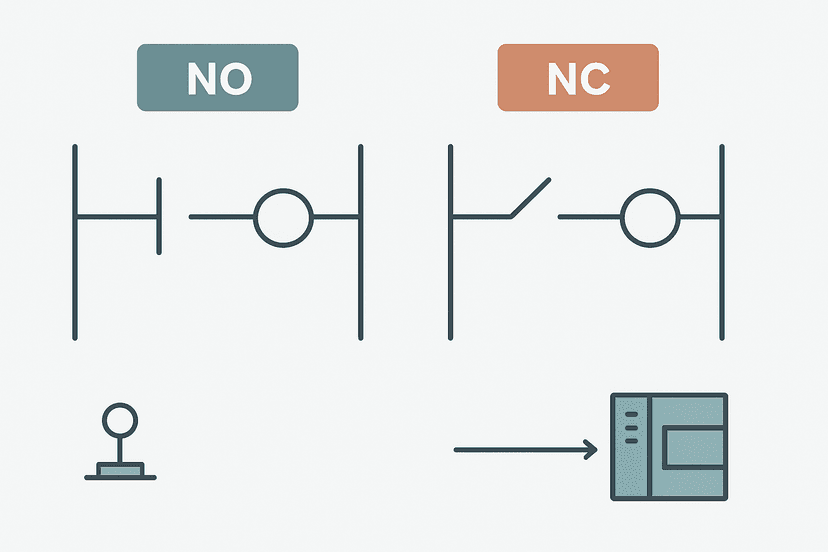
A wiring break on a normally closed (NC) sensor will open the contact and block the output, which is the safe failure direction. Using a normally open (NO) sensor as a permissive is dangerous: a broken wire looks like the permissive is satisfied. The NO vs NC contacts article covers this in detail. For guard switches and e-stops, always wire NC and program XIC so that a wire break trips the interlock.
Scan Order and One-Scan Glitches
If your interlock reads a bit that is written later in the same scan, you are reading last scan's value. On a fast machine this can allow a single scan where both outputs are momentarily true. Understand how the PLC scan cycle works and place mutual exclusion rungs before the rungs that write the coil bits wherever possible. If you can't, use a one-shot or a flag bit that resolves in a second pass.
Forcing Outputs in the Field
Forcing an output bypasses every software interlock. It's the fastest way to break a machine during commissioning. Use forcing only on inputs during PLC I/O diagnosis and always restore forces before handing the machine back. Log every force. Some sites lock force capability behind a password for exactly this reason.
Interlock Bypass Switches
Maintenance bypass switches are a real operational need, but they must be implemented carefully. The bypass bit should be latched (not momentary), displayed prominently on the HMI, and logged to the historian or SCADA system. A bypass that is left on after maintenance and not noticed is one of the most common causes of serious incidents. Wire a physical key-switch in series with the bypass input so it can't be enabled from the HMI alone.
Structuring Interlocks Across a Larger Program
On a machine with 20+ outputs, writing individual permissive chains on every rung becomes unmanageable. A cleaner approach: collect all global permissives into one internal bit called something like Sys_AllPermissives. Write all the individual conditions in series on one rung, output to that bit, then use XIC(Sys_AllPermissives) as the first contact on every output rung. When a new global condition needs adding, you change one rung instead of thirty.
Local permissives specific to one output (a position sensor for a particular cylinder, for example) stay on that output's own rung. This two-level structure, global then local, makes the logic readable and auditable. It also makes troubleshooting with online monitoring much faster: if Sys_AllPermissives is false, you know exactly where to look first.
For more complex machines, step through the PLC fault finding systematic method and treat a false interlock bit the same way you'd treat any other fault: confirm the input state at the module, check the wiring, then work back through the logic. Most interlock faults are wiring or sensor faults, not logic errors. The intermittent sensor fault guide is worth reading if a permissive is randomly dropping out.
_PERM_, _ILOCK_ or _GUARD_ make them instantly recognizable in the tag browser and in online monitoring. On Rockwell platforms, alias tags for physical I/O are your friend here: create a descriptive alias for Local:2:I.Data.5 called LidClosed_SW and the interlock reads like English.Interlocks and the Wider Machine Context
Interlocks don't exist in isolation. They interact with the HMI (the operator needs to see why the machine won't start), with the safety system (hardware interlocks must be separate from standard PLC logic), and with the sequence logic (step-based interlocks depend on state bits being correctly set). If you're building a full machine from scratch, look at the PLC elevator logic exercise and the car wash exercise to see how interlocks integrate into complete programs.
For exercises that focus specifically on interlock-heavy sequences, the 3-motor start sequence exercise and the tank fill control exercise both build out the permissive and run-confirm patterns in detail.
What to Read Next
If the interlock patterns here make sense, the logical next step is understanding exactly how the contacts you're placing work at the bit level. Start with XIC vs XIO contacts explained and NO vs NC contacts in PLC ladder logic for the foundational contact behaviour. Then read OTL and OTU latch coils explained to understand how to build fault latches that hold state correctly across power cycles and scan boundaries.
Frequently asked questions
What is an interlock in ladder logic?
What is the difference between a hardware interlock and a software interlock?
What is a permissive interlock in a PLC?
What is a mutual exclusion interlock?
How do you reset a latched fault interlock in ladder logic?
Can interlocks cause a PLC scan cycle problem?
Should I use XIO of a coil or XIO of the physical input for a mutual exclusion interlock?
What is a run-confirm interlock?
Do interlocks replace safety relays?
Now build it
You have just read about XIC and XIO and OTE. Reading a rung and making one behave are different skills, and the second one is the job.
Start / Stop Circuit
Beginnerabout 10 minThe first circuit every controls engineer learns: a motor that starts on a button press, keeps running when the button is released, and stops on a stop button, with stop always winning.
Build this rungFree, no signup, runs in your browser. See all 16 exercises.
Was this helpful?