OTL and OTU Latch Coils in Ladder Logic Explained
If you have ever tried to understand why a fault alarm stays on even after the fault clears, you have already bumped into a latching coil. The OTL and OTU instructions are simple, but the difference between them and a traditional seal-in rung trips up a surprising number of people, including experienced ones on their first Rockwell project.
What Is a Latching Coil in Ladder Logic?
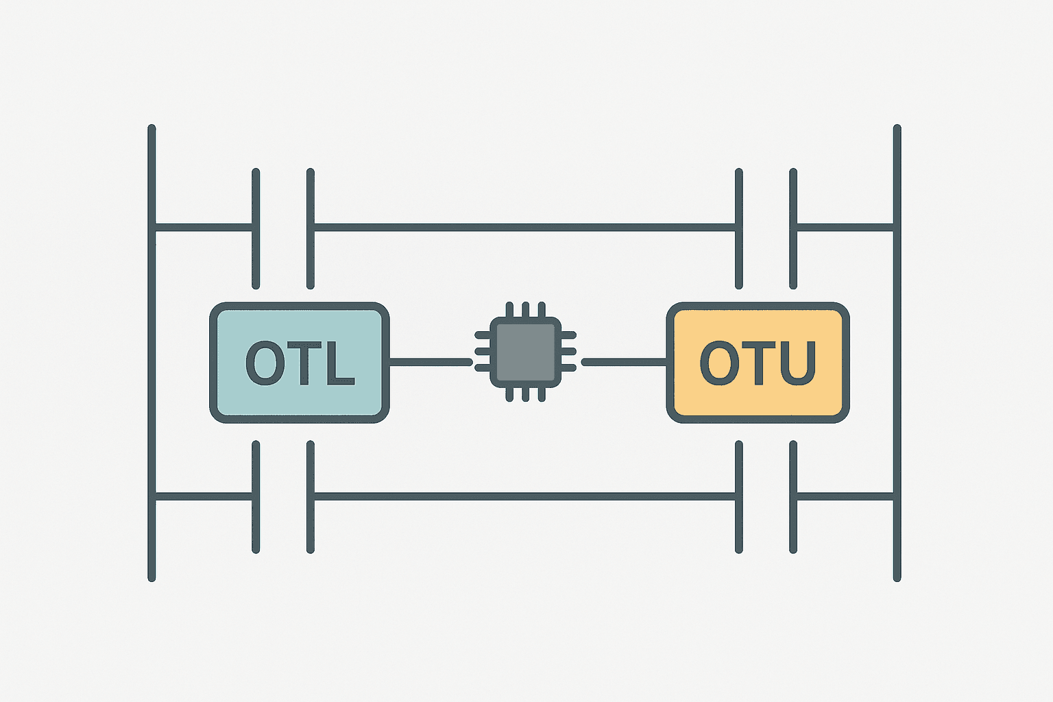
A latching coil in ladder logic is a retentive output instruction that sets a bit to 1 when its rung goes true and holds that bit at 1 even after the rung goes false. A separate unlatch coil instruction clears the same bit when its own rung goes true. In Rockwell Studio 5000 and ControlLogix/CompactLogix these are the OTL (Output Latch) and OTU (Output Unlatch) instructions. The bit they control is shared between both rungs, and the two rungs can sit anywhere in the program. Neither instruction is self-resetting. That is the entire point.
OTL vs OTU: How the Pair Works Together
Think of OTL as a momentary button that flips a toggle switch on, and OTU as the button that flips it off. The switch stays in whatever position it was last put in, regardless of what the buttons are doing right now. The PLC scan cycle evaluates every rung every scan. If the OTL rung is false and the OTU rung is also false, the bit does not change. It just sits there, holding its state.
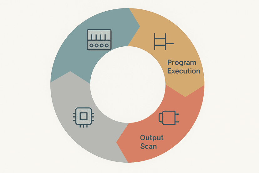
Understanding how the PLC scan cycle works step by step is important here. The scan executes top to bottom, left to right. If both the OTL rung and the OTU rung happen to be true in the same scan, the instruction that appears lower in the program wins. That is not a bug, but it will catch you out if you have not thought about rung order.
Latching Coil vs Seal-In Rung: The Real Difference
A seal-in rung holds itself energised by adding the output's own XIC contact in parallel with the momentary start pushbutton. That is the classic start/stop motor circuit you will find in every beginner tutorial. The key property of a seal-in is that the output stays on only as long as the rung logic remains true. The moment the Stop button opens or a fault breaks the rung, the coil drops and the seal-in contact opens with it. Everything resets automatically.
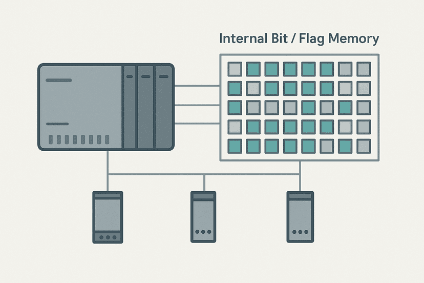
An OTL/OTU pair is different in two ways. First, the set and clear are on completely separate rungs with independent conditions. Second, the bit does not care whether the OTL rung is currently true or false. It was set, so it stays set. You need an explicit OTU rung to clear it. This matters a lot for PLC internal bits, flags and coils used as fault latches, where the intent is exactly that: the fault stays registered until an operator acknowledges it.
| Property | Seal-In Rung (OTE) | Latch/Unlatch (OTL/OTU) |
|---|---|---|
| How it holds state | Own contact in parallel with input | Bit retains last written value |
| Clears when... | Rung condition goes false | OTU rung goes true |
| Separate clear rung? | No | Yes, required |
| Typical use case | Motor run, valve enable | Fault latch, alarm, mode bit |
| Power-cycle behaviour | Clears (non-retentive OTE) | Clears unless tag is Retain |
A Real Fault-Latch Example in Studio 5000
Here is a pattern I use constantly: a pressure switch on a hydraulic unit trips a fault latch. The latch stays active even after pressure recovers, forcing an operator to acknowledge it before the machine can restart. The OTL rung fires on the rising edge of the pressure fault to avoid re-latching every scan while the fault is present.
Hydraulic Pressure Fault Latch with Operator Acknowledge (Studio 5000). Ladder logic (6 rungs): Rung 0: examine if HydUnit_PressureFault is on (XIC), then examine if Press_Fault_Rise is on (XIC), then latch output Press_FaultLatch (OTL). Rung 1: examine if Press_FaultLatch is on (XIC), then examine if HMI_FaultAck is on (XIC), then examine if HydUnit_PressureFault is off (XIO), then unlatch output Press_FaultLatch (OTU). Rung 2: examine if Press_FaultLatch is on (XIC), then energize output HMI_Press_AlarmActive (OTE). Rung 3: examine if Press_FaultLatch is off (XIO), then examine if Sys_StartCmd is on (XIC), then examine if HydUnit_PressureOK is on (XIC), then latch output Sys_Running (OTL). Rung 4: examine if HMI_StopCmd is on (XIC), then unlatch output Sys_Running (OTU). Rung 5: examine if Sys_Running is on (XIC), then energize output HydUnit_PumpOut (OTE). Rung 1: A one-shot (OSR) on the pressure fault signal latches the fault bit via OTL, so the latch fires once on fault onset rather than every scan. Rung 2: The OTU clears the latch only when the operator sends an HMI acknowledge AND the fault signal has already cleared, preventing an immediate re-latch. Rung 3: The latch bit drives an HMI alarm indicator. Rungs 4-5: The system can only start (OTL Sys_Running) when the fault latch is clear, and the stop command unlatches it. Rung 6: The physical pump output is driven by the running latch through a plain OTE.
The diagram above evaluates one scan. Run these exact rungs on a real scan cycle to watch the latching and the timers behave.
Run this in the simulatorNotice that the physical output (HydUnit_PumpOut) is driven by a plain OTE, not directly by an OTL. That is deliberate. Latching a physical output directly is risky because if the PLC restarts in a fault condition the bit could re-energise the actuator before your safety logic has a chance to evaluate. Keep latches on internal BOOLs and gate the physical output through a separate rung with safety conditions in series. This pairs well with what the emergency stop circuit wiring guide covers on the hardware side.
Retentive Memory: Does the Latch Survive a Power Cycle?
This is the question I get asked most often on Rockwell projects. In Studio 5000, OTL and OTU operate on standard BOOL tags by default. Standard tags are non-retentive, meaning they reset to 0 at power-up. If you want the latch to survive a controlled power cycle, you must tick the Retain checkbox in the tag's properties. The tag then lives in the retentive data area of the controller and will reload its last value on startup.
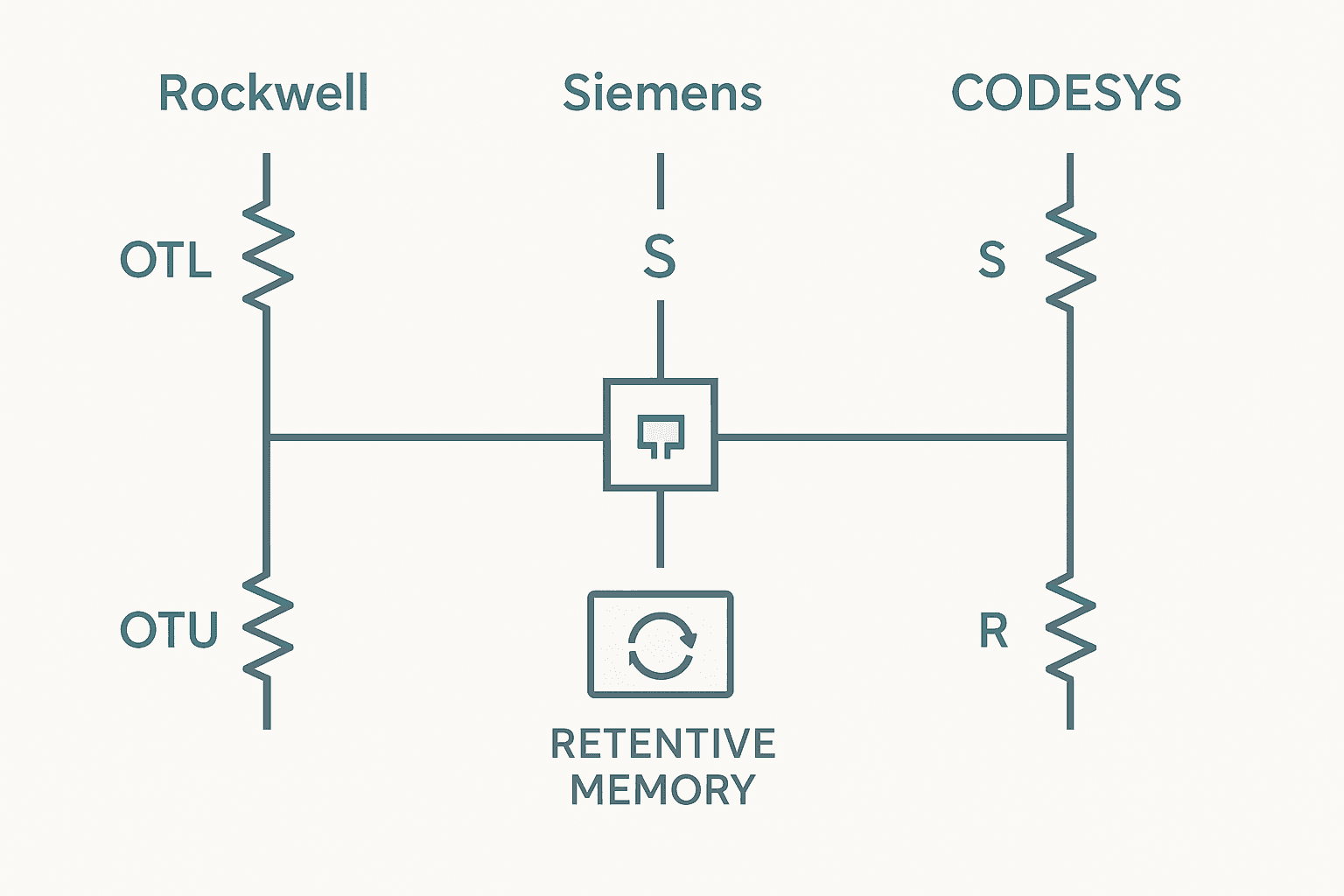
On Siemens S7-1200 and S7-1500, the equivalent approach is to store the latch bit in a retentive DB or to declare it in the retentive memory range under PLC properties. The S7-1200 Data Blocks guide explains retentive DB configuration in TIA Portal. In CODESYS you enable the RETAIN keyword on the variable declaration. The behaviour is consistent across platforms; the syntax just differs.
The Missing OTU Trap and Other Common Mistakes
The most common mistake with OTL/OTU is writing the latch rung and forgetting to write the unlatch rung before testing. The bit turns on and nothing clears it. You end up forcing bits in the programmer, wondering why the logic is broken, and then realising the OTU rung is just missing. I have done it. Everyone has.
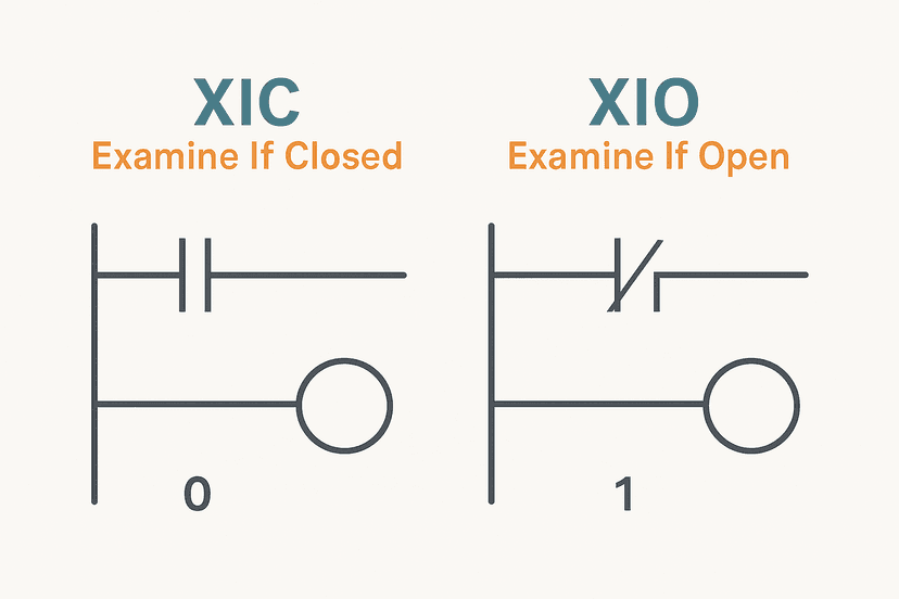
The second mistake is writing the OTU condition too broadly. If your OTU rung clears the fault latch the moment the fault signal disappears, you have effectively built a seal-in, not a latch. The operator never has a chance to see the alarm. Always require an explicit acknowledge input in series on the OTU rung, and use XIC vs XIO contacts correctly to guard the acknowledge. A typical pattern is: OTU fires only when (FaultAck is true) AND (fault input is already clear). That way acknowledging during an active fault does nothing, which is exactly what you want.
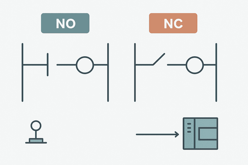
A third gotcha: if you use OTL on a BOOL that is also written by an OTE somewhere else in the program, the OTE will overwrite the OTL value on every scan where the OTE rung is evaluated. Never mix OTE and OTL/OTU on the same bit. Pick one mechanism and stick to it. This is covered in more detail in the normally open vs normally closed contacts breakdown when discussing coil conflicts.
Where Latching Coils Belong in a Real Program
Fault latches are the most obvious application, but OTL/OTU shows up in a few other places too:
- Alarm management: latch an alarm bit on the rising edge of a fault, clear it only on acknowledge. See how this feeds into HMI alarm configuration for the display side.
- Mode and state bits: latch a 'recipe loaded' or 'batch complete' bit that persists across scan cycles until the next stage of the sequence clears it.
- Permissive interlock latches: latch a 'safety check passed' bit after a timed verification, so the machine does not have to re-run the check on every scan.
- Step sequencers: some sequencer styles use a latched step bit per step rather than a counter, particularly when steps can be held for variable durations.
- Communication fault indicators: latch a comms loss event so the operator sees it even if the connection briefly recovers. This is the exact pattern used in the EtherNet/IP communication loss diagnosis guide.
Siemens and CODESYS Equivalents at a Glance
The OTL/OTU naming is Rockwell-specific. Every platform has the same concept under different labels. In TIA Portal LAD (S7-1200, S7-1500) you will see (S) and (R) coils that work identically. In Structured Text in TIA Portal you would write FaultLatch := TRUE; and FaultLatch := FALSE; inside conditional IF blocks, which is functionally the same thing. CODESYS uses S and R coils in the LAD editor, or SR/RS function blocks. Omron Sysmac Studio uses SET and RSET instructions, as covered in the Omron Sysmac Studio getting-started guide. The logic pattern is universal.
Troubleshooting a Latch That Will Not Clear
If an OTL bit is stuck on and the OTU rung looks correct, go online and check the actual rung status in the programmer. Look at each contact on the OTU rung individually. Nine times out of ten the fault input is still physically active (the fault has not cleared), or the acknowledge pushbutton wiring is not making contact. Online monitoring shows you which contact is holding the rung open without any guesswork.
If the rung shows all contacts true but the bit is still set, check whether another OTL rung is re-latching the bit in the same scan. Search all uses of the tag in your program. Studio 5000 lets you right-click the tag and select Cross Reference to find every rung that reads or writes it. Do that first. It is the fastest way to find a conflicting write.
For wiring-side issues (acknowledge button not registering, fault sensor stuck), the PLC digital input fault diagnosis guide and the multimeter I/O testing guide are the right next stops.
Keep Learning
Latching coils are one piece of the broader ladder logic picture. To see how they fit into a complete working program, the PLC bottle filling machine project walks through a full sequence that uses fault latches, timers, and counters together. For a deeper look at the contacts that drive latch rungs, XIC vs XIO: Ladder Logic Contacts Explained covers every case. And if you are preparing for an interview, Ladder Logic Interview Questions: Real Answers includes several OTL/OTU questions with the answers interviewers are actually looking for.
Frequently asked questions
What is an OTL coil in ladder logic?
What is the difference between OTL/OTU and a seal-in rung?
Do OTL bits survive a PLC power cycle?
Can two rungs write OTL and OTU to the same bit safely?
What happens if the OTU rung is missing from the program?
Are OTL and OTU the same as SET and RESET in other platforms?
When should I use a seal-in rung instead of OTL/OTU?
What is the Siemens equivalent of OTL in TIA Portal ladder?
Can I use OTL on a physical output like a valve solenoid?
Now build it
You have just read about OTU and OTL and XIO. Reading a rung and making one behave are different skills, and the second one is the job.
State Coil / Fault Coil
Intermediateabout 15 minA fault lamp that latches ON when any alarm condition occurs, even briefly, and only clears on Reset. And if the condition is still present when Reset is released, the fault comes right back.
Build this rungFree, no signup, runs in your browser. See all 16 exercises.
Was this helpful?