ethernet/ip
communication faults
plc troubleshooting
EtherNet/IP Communication Loss: How to Diagnose It
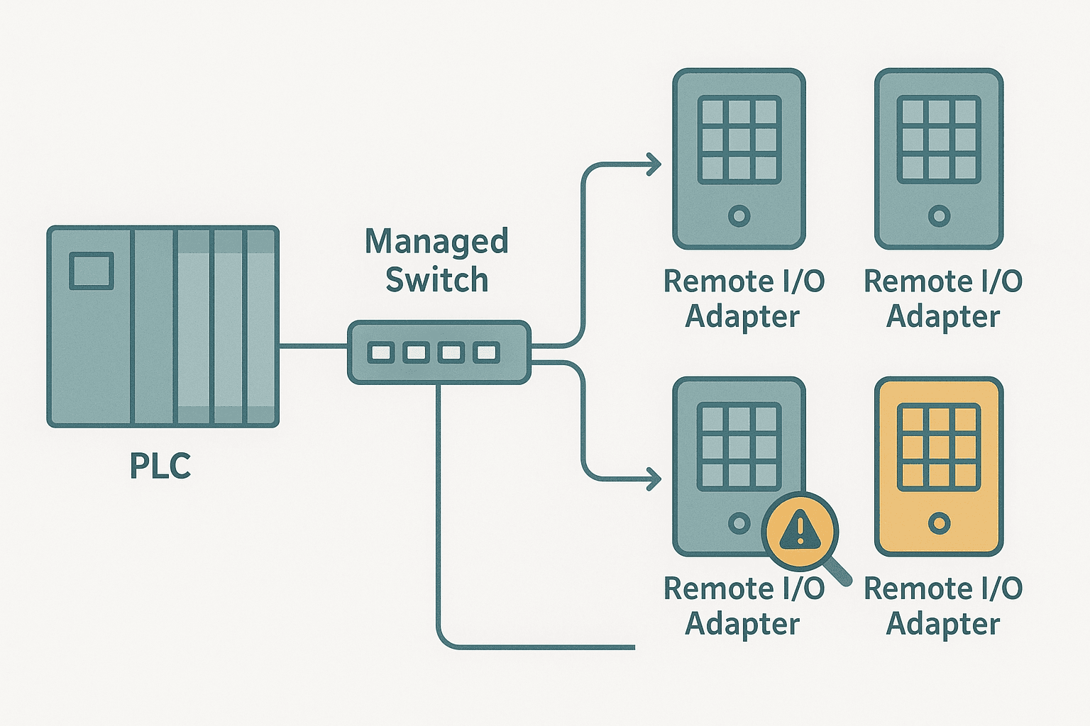
You are online in Studio 5000 and the I/O tree lights up red. One or more EtherNet/IP devices are faulted, the controller has gone to major fault mode, and the line is down. If you have been there, you know the pressure. EtherNet/IP communication loss is one of the most common calls I get from sites running ControlLogix or CompactLogix, and the root cause is almost never where the PLC fault log points first.
What Is EtherNet/IP Communication Loss?
EtherNet/IP communication loss occurs when a Logix scanner cannot maintain a CIP (Common Industrial Protocol) I/O connection to an adapter device within the configured timeout window. The scanner declares a connection fault, the controller sets the associated I/O data to its configured fault state, and depending on how the program handles it, the machine either safe-stops or continues with stale data. The fault is logged in the controller diagnostics and shown as a red X on the module in the I/O tree.
Layer 1: Start at the Cable and Connectors
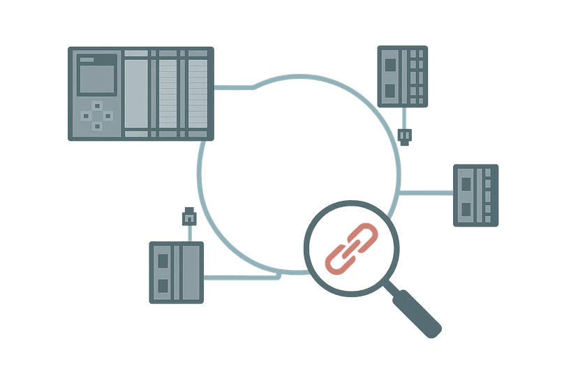
Every EtherNet/IP fault diagnosis starts at the physical layer. This is not glamorous, but I have fixed more communication faults with a cable swap than with any configuration change. Check the port LEDs on the switch and on the device itself. A solid green link LED that blinks amber during data transfer is healthy. No link light at all means the cable is open or the port is dead.
- Inspect RJ45 connectors for bent pins or a clip that no longer locks. A connector that looks seated can still have a marginal contact.
- Check for Cat5e minimum on any new runs. Cat5 (not e) is not rated for the 100 Mbps full-duplex that EtherNet/IP requires in practice.
- Watch for cable routed next to VFD output cables or high-current motor leads. EtherNet/IP is more tolerant than analog signals, but sustained radiated noise on long parallel runs does cause intermittent faults. The post on control panel wire routing and segregation covers safe separation distances.
- Test the cable with a TDR or at minimum a simple continuity tester. A marginal crimp that passes continuity can still fail under vibration.
Layer 2: Check the Switch Configuration
Unmanaged switches are fine for small cells, but most plants run managed switches and that introduces configuration faults that look exactly like device failures. The two biggest culprits are Spanning Tree Protocol and IGMP snooping.
Classic STP (802.1D) puts a port through a 30 to 50 second learning and blocking phase every time the link comes up. The EtherNet/IP scanner times out and faults the module long before STP lets traffic through. The fix is to enable RSTP (802.1w) globally and set device-facing ports to edge mode (Cisco calls it PortFast). Do this on every port connected to a PLC, drive, or remote I/O adapter.
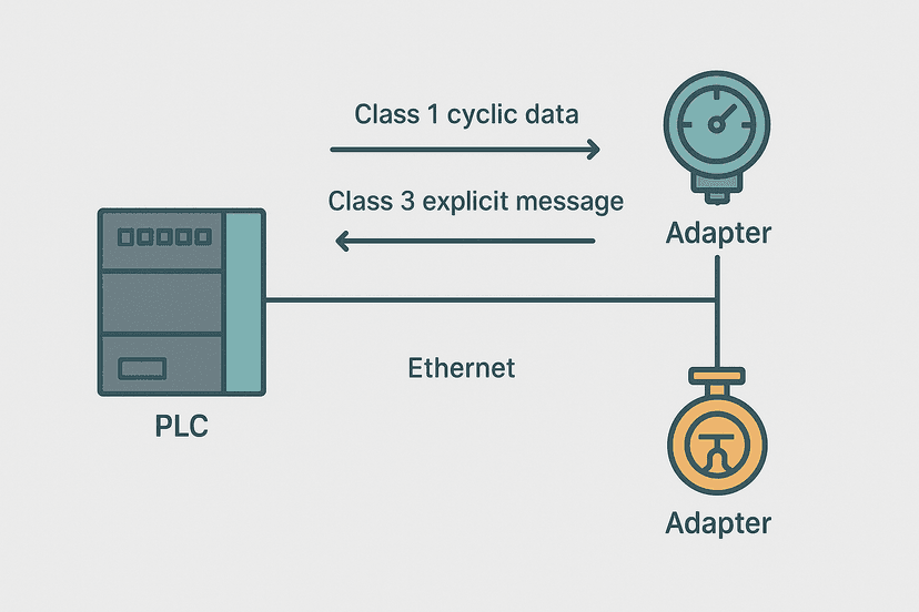
CIP uses multicast for Class 1 cyclic I/O. Without IGMP snooping enabled on the switch, every multicast packet floods all ports. On a loaded network with dozens of I/O modules, this alone can saturate 100 Mbps ports and cause timeouts. Enabling IGMP snooping confines multicast traffic to ports that have subscribed to it, which dramatically reduces switch load. Rockwell publishes network design guidance in their ENET-AT001 network infrastructure guide, which is worth reading if you manage the switch layer.
Layer 3: IP Address Conflicts and DHCP
Every EtherNet/IP device must have a unique static IP address. DHCP has no place on a control network: a lease renewal at the wrong moment will change a device's address mid-run and immediately drop the CIP connection. If the device boots with a DHCP-assigned address that differs from what the scanner expects, you get an immediate connection fault with error code 16#0111.
IP conflicts are sneakier. If two devices share an address, the ARP table on the switch alternates between their MAC addresses. The scanner's connection switches between the real device and the imposter with each ARP update. You see the module fault, recover, fault again with no apparent cause. To confirm, log into the switch and check the ARP table for duplicate IP entries, or capture traffic with Wireshark and filter on the suspect IP. You will see two different source MAC addresses on the same IP.
For background on how the scanner and adapter roles work in EtherNet/IP, the post on EtherNet/IP scanner vs adapter explains the CIP originator-target model clearly.
Layer 4: CIP Timeout and RPI Settings
Once the physical and network layers are clean, look at the connection parameters inside Studio 5000. The RPI (Requested Packet Interval) defines how often the adapter must send data. The connection timeout is typically 4x the RPI. So an RPI of 5 ms means the connection faults if no packet arrives within 20 ms. On a loaded switch or a slow CPU, that is tight.
| Device Type | Typical Safe RPI | Minimum Practical RPI |
|---|---|---|
| Digital I/O module (1734 POINT I/O) | 10 ms | 2 ms |
| Analog I/O module | 20 ms | 5 ms |
| Variable frequency drive | 20 ms | 10 ms |
| Remote I/O adapter (1738, 1794) | 10 ms | 2 ms |
| Third-party device (generic CIP) | 50 ms | 20 ms |
To change the RPI in Studio 5000, go offline, right-click the module in the I/O tree, choose Properties, and select the Connection tab. Increase the RPI incrementally: try doubling it first and see if the faults stop. If they do, the network is too loaded for the original setting. Adding bandwidth (Gigabit uplinks between switches) or splitting devices across VLANs is the longer-term fix.
Also check the connection type. Class 1 (cyclic) connections carry I/O data and are time-sensitive. Class 3 (explicit messaging) is used for configuration reads and writes. A Class 3 request that blocks due to a slow device can compete with Class 1 traffic on the same port if the device does not prioritise correctly. If you have ladder logic doing frequent MSG instructions to a device while also running Class 1 I/O, reduce MSG frequency or add a timer gate. The PLC scan cycle problems post covers how scan-cycle overload interacts with communication timing.
Reading the Fault Code in Studio 5000
When a module faults, Studio 5000 stores a connection error code. Go to the module Properties, Connection tab. You will see an error code in hex. Here are the ones you will meet most often:
- 16#0203 (Connection Timeout): The adapter stopped sending within the timeout window. Classic cable, switch STP, or RPI issue.
- 16#0204 (Connection Not Found): The scanner cannot open a new connection. Often means the device is already at its connection limit, or the electronic key (revision) does not match.
- 16#0111 (Target Device Not Available): IP address is unreachable. Check cable, switch port, and IP address configuration.
- 16#001F (Connection Manager General Error): Often a firmware or module type mismatch. Confirm the module catalog number and revision in the I/O tree match the physical hardware.
- 16#0302 (Ownership Conflict): Two controllers are trying to own the same I/O module. Only one controller can own a given connection at a time.
The controller fault log (Controller Properties, General tab, Fault Log) also stores timestamped entries. Cross-reference the fault time with any process events, shift changes, or maintenance activity. On one commissioning I did at a bottling plant, the comm faults always happened at 06:00. Turned out the night-shift electrician was switching a nearby panel light on and it was on the same 24 V rail as the managed switch, causing a 200 ms brownout that killed the switch's uplink. The PLC power supply faults post has a good section on exactly this type of shared-rail problem.
Electronic Key Mismatches and Firmware Versions
Studio 5000 lets you configure an electronic key for each module. The key can be set to Exact Match, Compatible Match, or Disabled. With Exact Match, if the physical module's major revision differs from what is in the project, the controller refuses to own it and the module faults with a keycheck error. This trips people up after a warranty replacement where the new module ships with a newer firmware revision. Set the key to Compatible Match for most I/O modules unless you have a specific reason to lock to an exact revision.
For drives connected over EtherNet/IP, check that the Add-On Profile (AOP) version in your project matches the drive's firmware. A mismatch here causes a 16#001F error and the drive will not come online. If you have recently updated drive firmware, you may need to update the AOP in Studio 5000 as well. The VFD fault codes post covers drive-side diagnostics that complement this network-side view.
Handling Comm Loss in Ladder Logic
A good program does not just fault out when an EtherNet/IP device drops. It detects the loss, puts the machine into a safe state, and raises a specific alarm so operators know which device is gone. In Studio 5000, every I/O module has a .CommStatus or .ConnectionFaulted member in its input data tag. For a 1734 POINT I/O adapter, the tag is AdapterName:I.ConnectionFaulted. You can latch an alarm on the rising edge of that bit.
EtherNet/IP Adapter Comm Loss: Fault Latch and Safe-State Output (Studio 5000). Ladder logic (4 rungs): Rung 0: examine if Remote_IO_Adapter:I.ConnectionFaulted is on (XIC), then examine if CommLoss_Rise is on (XIC), then latch output CommLoss_FaultLatch (OTL). Rung 1: examine if CommLoss_FaultLatch is on (XIC), then examine if Remote_IO_Adapter:I.ConnectionFaulted is off (XIO), then examine if HMI_CommFaultAck is on (XIC), then unlatch output CommLoss_FaultLatch (OTU). Rung 2: examine if CommLoss_FaultLatch is on (XIC), then energize output HMI_CommLoss_Alarm (OTE). Rung 3: examine if CommLoss_FaultLatch is off (XIO), then examine if Process_RunCmd is on (XIC), then energize output Process_Enable (OTE). Rung 1: Rising-edge one-shot latches the alarm on first scan of ConnectionFaulted going true. Rung 2: Operator ack clears the latch only after the connection is restored (XIO confirms the fault bit is gone). Rung 3: Drives the HMI alarm bit. Rung 4: Process enable is gated off while comm is faulted, putting the cell in a safe state.
This pattern prevents the machine from running blind on stale output data. Without it, the controller continues executing ladder logic with the last-known values of the remote inputs, which can cause unexpected actuator movement. The PLC communication faults guide covers how different PLC platforms handle fault state configuration, and it is worth reading alongside this post.
PROFINET vs EtherNet/IP: Different Fault Behaviour
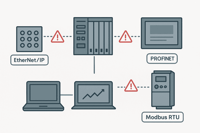
If you work across both Siemens and Rockwell platforms, note that PROFINET handles communication loss differently. PROFINET has a watchdog timeout configurable per device in hardware configuration, and the IO controller substitutes zero data by default when a device drops. EtherNet/IP's CIP connection model requires explicit fault handling in the application, as shown in the ladder above. The PROFINET communication loss diagnosis post is the parallel reference for Siemens systems.
A Quick Diagnostic Checklist
- Check link LEDs on the switch port and the device. No link means physical layer fault.
- Ping the device IP from the engineering laptop. No reply confirms network or IP issue.
- Check the switch ARP table for duplicate IP entries.
- Confirm STP is set to RSTP and edge ports have PortFast enabled.
- Check IGMP snooping is enabled on the switch.
- Read the module fault code in Studio 5000 Properties, Connection tab.
- Compare the module catalog number and revision against the physical label.
- Check the electronic key setting (Compatible Match vs Exact Match).
- Review RPI settings. Double any value below 10 ms and retest.
- Check the controller fault log timestamp and correlate with process events.
- Monitor MSG instruction frequency if explicit messaging runs alongside Class 1 I/O.
For faults that are intermittent and hard to catch live, use the PLC troubleshooting with online monitoring techniques to set up data logging and trend the .ConnectionFaulted bit alongside process variables. You can often correlate comm drops with high motor starts, VFD switching events, or specific machine states. The intermittent sensor faults post has a good section on how to set up triggered capture for events that only last one or two scans.
Keep Learning
EtherNet/IP communication loss sits at the intersection of network engineering and PLC programming. Once you have cleared this fault, it is worth building out your broader fault diagnosis toolkit. The PLC fault finding systematic approach gives you a repeatable 6-step method you can apply to any fault type, and the PLC communication faults guide covers Modbus, PROFIBUS and serial faults alongside EtherNet/IP. If you suspect the problem is upstream in your drive or VFD, the VFD fault codes troubleshooting guide will pick up where this post leaves off.