PLC Power Supply Faults: How to Diagnose Them
A PLC that randomly resets, drops I/O points or throws CPU fault codes is the kind of problem that can eat an entire shift. Nine times out of ten, the first thing a technician checks is the program logic or the field wiring. The power supply sits there looking fine, green LED lit, and nobody touches it. That is a mistake. PLC power supply faults are responsible for more unexplained nuisance trips and intermittent faults than most engineers expect, and they are straightforward to diagnose once you know the method.
What Are PLC Power Supply Faults?
PLC power supply faults are conditions where the voltage or current delivered to the PLC rack, CPU or field I/O circuits falls outside the operating specification of the hardware. This includes low output voltage, excessive AC ripple riding on the DC rail, overcurrent conditions, input voltage dropout and internal component failures. Any of these can cause symptoms ranging from total system shutdown to subtle, intermittent misbehavior that is almost impossible to catch without systematic measurement.
The Two Power Rails You Need to Understand
Before you start measuring, get clear on what you are actually powering. A typical PLC system has two distinct supply rails, and they fail independently.
- Backplane or rack power: The internal supply built into the rack power supply unit (PSU). On a Siemens S7-300/400 or Rockwell ControlLogix rack, this module converts mains input to a regulated 5 VDC (and sometimes 24 VDC) rail that feeds the CPU and module electronics over the backplane. You cannot measure this rail directly on most platforms without specialist tools, but the PSU module will indicate a fault via a fault LED or diagnostic bit.
- 24 VDC field power: A separate DIN-rail mounted switched-mode power supply (SMPS) that powers your sensor inputs, output loads and sometimes communication modules. This is the rail you can and should measure at the terminal block with a multimeter. It is also the one that causes the most field-level problems.
On modular systems like the Siemens S7-1200, the CPU has an integrated 24 VDC supply for powering a small number of digital inputs directly, in addition to whatever external 24 VDC SMPS you wire to the L+ and M terminals. If that internal supply is marginal, you will see input misbehavior on the CPU's own onboard I/O before any expansion module is affected. Worth knowing before you replace an expansion module that is actually fine.
Classic Symptoms of PLC Power Supply Faults
These symptoms do not always point exclusively to a supply fault, but any of them should put the power supply on your suspect list early:
| Symptom | Most Likely Supply Cause |
|---|---|
| Random CPU resets or STOP transitions | Output voltage dropout below CPU minimum (often 20.4 V for 24 VDC nominal) |
| I/O modules showing fault or offline | Backplane PSU overloaded or output voltage sagging under load |
| Intermittent sensor inputs flickering | 24 VDC field supply ripple or voltage too low for input threshold |
| PROFINET or EtherNet/IP comms dropouts | Ripple corrupting PHY logic supply; check after ruling out cabling |
| Modules initialize on cold start but fault after warm-up | Thermal derating: supply running too hot, output droops with temperature |
| Blown fuses on output cards repeatedly | 24 VDC supply crowbarring or surging above 28 V on startup |
If you are seeing any of these alongside CPU fault codes, check the PLC CPU fault diagnosis guide alongside this article. The two often go together.
Step-by-Step PLC Power Supply Fault Diagnosis
Step 1: Check the LED Indicators First
Most rack PSUs and DIN-rail SMPSs have a green DC OK LED. If it is off or flickering, that is a hard fault and the supply needs to come out. If it is steady green but you still have symptoms, the LED only confirms the supply has not completely collapsed. Plenty of supplies fail with the LED lit. Do not stop here.
Step 2: Measure Output Voltage Under Load
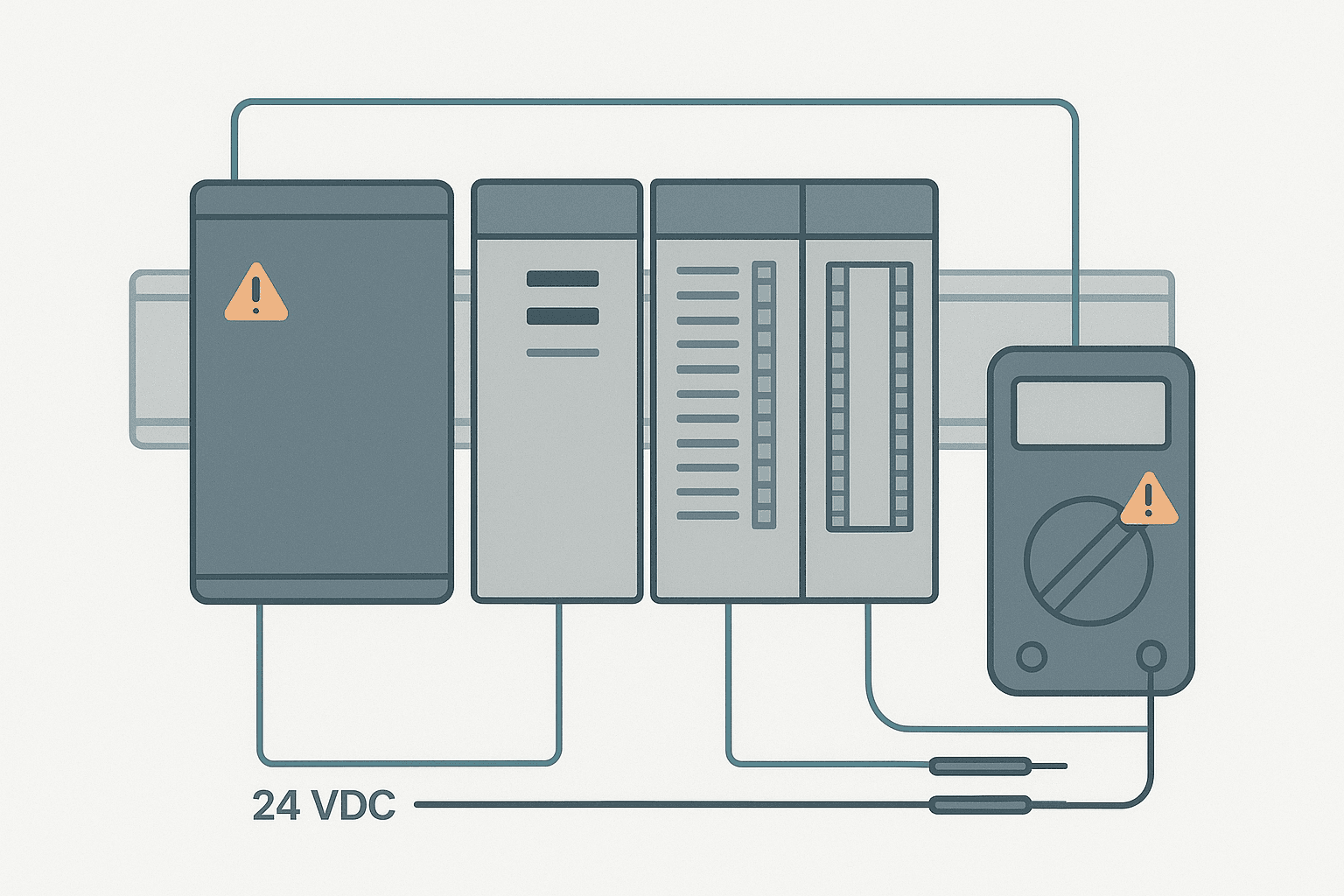
Put your multimeter on DC volts and measure at the output terminals of the supply, or at the PLC rack's 24 V input terminals if they are accessible. Do this while the system is running normally, not powered down. You want to see the voltage under real operating load.
A 24 VDC supply should read between 22.8 V and 25.2 V under load (plus or minus 5%). Below 22 V is the danger zone for most PLC CPUs. The Siemens S7-1200, for example, specifies a minimum supply voltage of 20.4 V. A Rockwell Micro850 specifies 20.4 V minimum as well. If you are reading 21 V under load, you have about 0.6 V of margin and any additional load or temperature rise will push you over the edge.
Step 3: Measure AC Ripple on the DC Rail
Switch your multimeter to AC millivolts (not AC volts) and measure across the supply output terminals while the system runs. A healthy SMPS will show under 50 mV peak-to-peak. Anything over 200 mV is worth flagging. Over 500 mV and you have a supply that is likely to cause comms errors and erratic I/O behavior even though the DC reading looks acceptable. I have seen PROFINET communication faults that disappeared the moment we swapped a failing 24 VDC SMPS that was measuring 480 mV ripple but still showed 24.1 V DC. The comms engineers had spent two days chasing cable continuity. Ripple was never on their list.
Step 4: Check the Supply Input Side
Measure the AC input voltage to the supply while the system is under load. Many industrial SMPSs accept 100 to 240 VAC, but if your mains supply is sitting at 95 VAC due to a transformer tap issue or heavy site load, the supply may be operating near its regulation limit. Also verify the supply input fuse or breaker has not partially failed. A fuse or breaker that is beginning to fail can add enough resistance in series with the input to starve the supply.
Step 5: Calculate and Verify the Load Budget
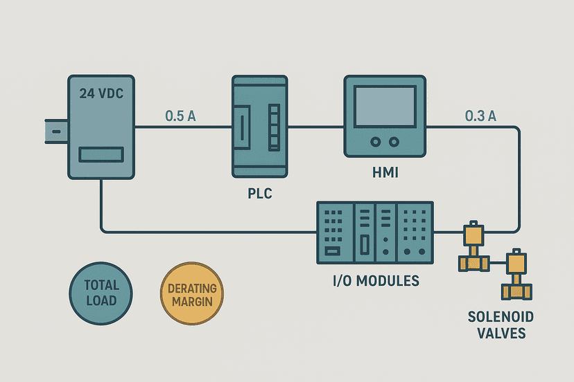
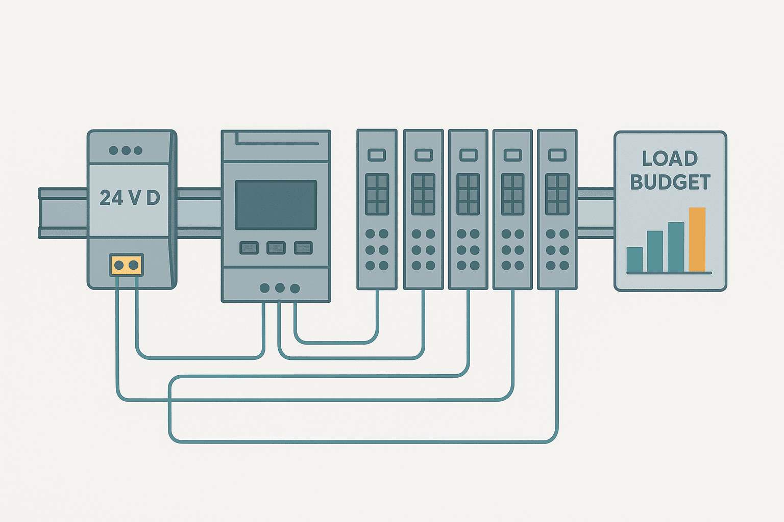
Add up every load connected to the 24 VDC supply: PLC rack draw (from the system manual), each I/O module current draw, sensors, solenoid valve pilots and any relay coils. Compare this to the supply's rated output current. If the total sits above 80% of rated capacity, the supply is running hotter than it should and will derate as it heats up. Refer to the types of PLC modules article for a breakdown of typical module power draws by category.
Step 6: Check Grounding and DC Common
A missing or high-resistance DC common bond between the 0 V terminal of the supply and the panel earth rail causes floating reference issues that produce symptoms identical to a low-voltage fault. Measure the resistance between the supply 0 V terminal and the panel earth stud with your meter on the low ohms range. It should be under 1 ohm. Anything higher and you need to trace the bonding conductor and fix it. For a detailed look at correct grounding practice, see Control Panel Grounding: The Right Way to Do It.
Rack PSU Faults vs External 24 VDC Supply Faults
It is worth being clear on which supply is actually the problem. If the rack PSU (the module that slots into the PLC rack itself) is failing, you will typically see the CPU go offline and all modules lose power simultaneously. The PLC's diagnostic buffer will show a power supply fault event with a timestamp. On a Siemens S7-300, the PSU module has a DC5V OK LED that is separate from the 24 VDC LED. If the 5 V rail fails, everything dies. You will not get much diagnostic data because the CPU itself has lost power.
If the external 24 VDC SMPS is failing, you will typically see field I/O behave erratically first, because sensors lose their supply voltage before the CPU loses its logic supply. The CPU may stay online and log I/O faults while the field supply droops. This is actually useful: if the CPU stays up and you can see I/O faults in the diagnostic buffer, the backplane supply is probably fine and you are looking at the 24 VDC field supply. Use online monitoring while the fault is occurring to confirm which I/O points are dropping and whether the CPU is staying in RUN mode.
Field-Verified Gotchas
- Shared 24 VDC supply with a VFD control circuit: VFD control boards draw surge current on enable that can momentarily drag down a shared 24 VDC supply. If your PLC resets at the same moment a drive starts, you have found your fault. Separate the PLC supply from the drive control supply. Check the VFD fault codes guide if the drive itself is also faulting.
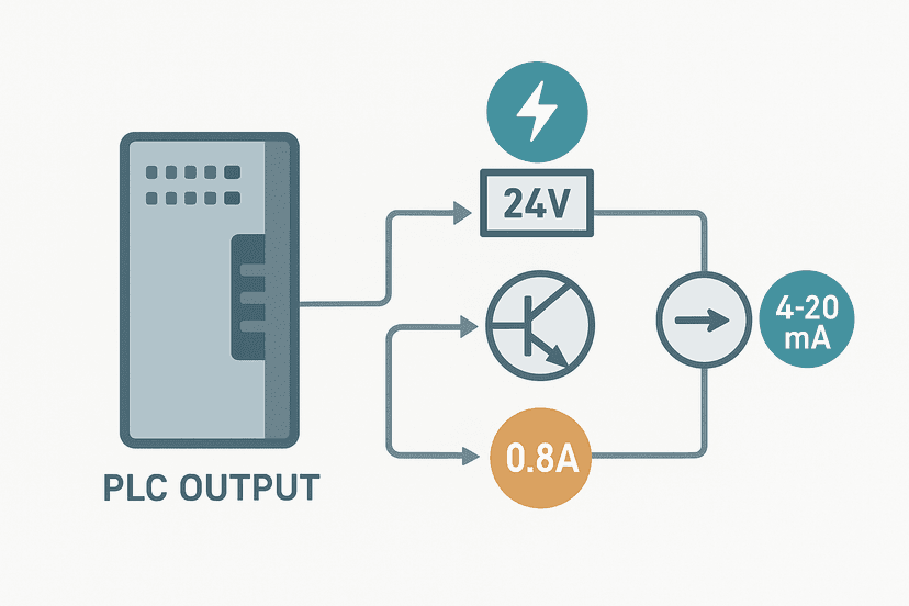
- Analog input cards with a shared 24 VDC sensor supply: A short or overloaded transmitter loop on a 4-20 mA input can pull down the sensor supply enough to affect nearby digital I/O on the same rail. If you are troubleshooting an analog wiring issue, see PLC Analog Input Wiring: 4-20 mA Step by Step and check whether your analog supply is separate from your digital I/O supply.
- 24 VDC supply with adjustable output trimmer: Some SMPS units ship with the output trimmer set to 24.0 V and have a range of 22 to 28 V. If a previous technician turned the trimmer down to 22 V for an unknown reason, you will get marginal operation that only fails under full load or at high temperature.
- Inrush on output cards at power-up: A rack with 16 or 32 relay outputs energizing simultaneously at startup can pull several amps of inrush for 20 to 50 ms. If your supply has slow overcurrent protection, it may fold back during this period. Add a startup delay in logic to stagger output energization, or verify the supply's rated inrush handling. You can look at how PLC output faults relate to this kind of issue.
When to Replace vs Repair
For DIN-rail SMPSs from Phoenix Contact, Siemens SITOP, or Rockwell Bulletin 1606, the answer is almost always replace, not repair. A 10 A 24 VDC SMPS costs 80 to 200 USD. The labor to repair it, and the risk of it failing again six months later, makes repair uneconomical. Keep a spare on the shelf. For rack PSU modules (Siemens 6ES7 307 series, Rockwell 1756-PA75 and similar), the cost is higher (300 to 800 USD) and you might consider an RMA repair from the vendor if you have time. But for a production line, the downtime cost of waiting for a repair usually makes a new module the right call.
Preventive Checks to Add to Your PM Schedule
- Measure 24 VDC output voltage under load every 6 months. Log the reading so you can spot a slow drift before it causes a fault.
- Check supply output terminal temperature with an infrared thermometer. A supply running over 60 degrees C at the case is working too hard.
- Inspect DC output terminal connections for loose screws and corrosion. A 0.5 ohm terminal resistance at 5 A drops 2.5 V, which is enough to push you below CPU minimum.
- Verify panel ventilation: blocked filters raise ambient temperature and directly derate SMPS output capacity.
- Review the load budget any time you add modules, sensors or outputs to an existing panel.
What to Read Next
Power supply faults are one piece of the troubleshooting picture. Once you have confirmed the supply is solid, use PLC I/O Fault Diagnosis with a Multimeter to systematically test your input and output circuits, and visit PLC Troubleshooting with Online Monitoring to learn how to use your programming software as a live diagnostic tool. If the problem turns out to be CPU-level, PLC CPU Faults: How to Diagnose Them Step by Step picks up exactly where this guide leaves off.
Frequently asked questions
What are the most common symptoms of a PLC power supply fault?
What voltage should I measure at a 24 VDC PLC power supply output?
Can a failing power supply cause PLC communication faults?
How do I test a PLC power supply with a multimeter?
Why does my PLC only reset at certain times of day?
What is backplane power and how does it differ from 24 VDC field power?
How much load current margin should a PLC power supply have?
Can a bad ground cause PLC power supply faults?
Should I replace a PLC power supply if it measures correct voltage?
Learn this by building it
There is a PLC in this site. It runs a real scan engine, checks your logic against the same tests a working machine would fail, and needs no download and no account.
Open the exercisesFree, no signup, runs in your browser. See all 16 exercises.
Was this helpful?