PLC Output Faults: How to Diagnose Them Fast
A PLC output fault stops production. The output bit is ON in the software, the status LED on the module is lit, but nothing moves. Or the output stays stubbornly OFF no matter what the logic says. Either way, you need to find the fault fast, and the fastest path is a structured diagnostic sequence, not random poking with a screwdriver.
What Is a PLC Output Fault?
A PLC output fault is any condition where the physical output channel fails to deliver the expected signal to the field device, even though the controller logic is commanding it to. This covers a failed relay contact, a blown transistor, a missing supply voltage, a broken wire, an overloaded analog channel, or a blown bank fuse. The fault can live in the module hardware, the wiring, the load itself, or the supply feeding the output commons. Knowing which layer has failed is the entire job.
Step 1: Separate the Logic from the Hardware
Before you touch a meter, go online. Pull up the PLC troubleshooting online monitoring view and watch the output bit in real time. The question you are answering: is the PLC commanding the output ON, or is the logic preventing it?
- Output bit is OFF and you expected it ON: the fault is in the logic. Check your conditions, timer done bits, fault latches and interlocks before touching any wiring.
- Output bit is ON and the load does not energize: the fault is in the hardware layer. Continue with the physical checks below.
- Output bit flickers or toggles rapidly: the logic is oscillating, or you have a broken field wire creating a false feedback condition.
If your output bit is OFF when you expect it ON, check XIC vs XIO contact logic and NO vs NC contact assignments before assuming hardware failure. A wrong contact type has fooled more than one experienced engineer.
Step 2: Check the Output Module Supply and Fuses
Most output modules use a separate supply rail for the output commons, independent of the logic supply. If that rail is dead, every channel in the bank will appear to command correctly (the bit is ON) but nothing energizes. This catches people out constantly.
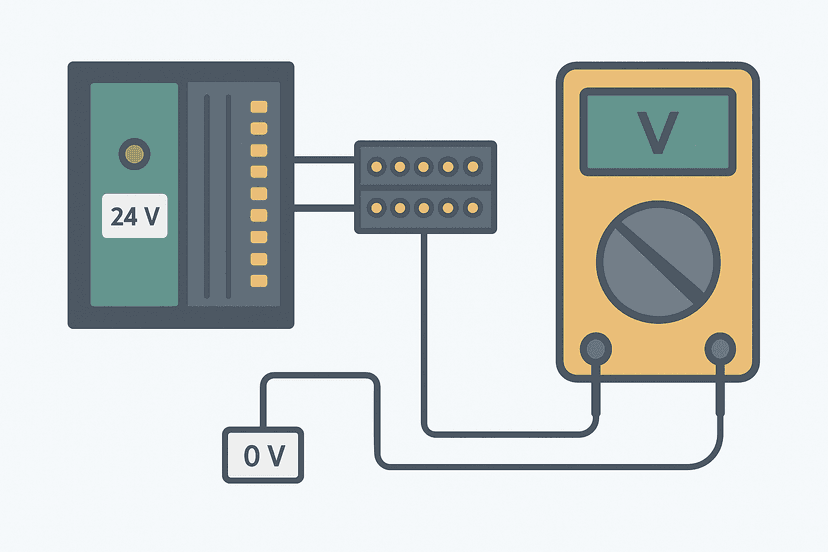
Measure voltage at the output common terminal with reference to the load return. For 24 VDC digital modules you expect 23.5 V to 26 V. For 120 VAC modules you expect 108 V to 132 V. No voltage here means no output, regardless of what the software says.
Then check the bank fuse. Output modules typically group 4, 8 or 16 channels per fuse. A short-circuit on any one channel can blow the fuse and kill the whole bank. Measure voltage across the fuse body with the circuit live: any reading above a few millivolts means the fuse has blown. See PLC I/O fault diagnosis with a multimeter for the exact voltage-across-fuse technique.
Step 3: Force the Output and Measure at the Terminal
With the machine in a safe, isolated state, force the output ON from the software. Now measure at the module terminal screw, not at the load. This isolates whether the module is switching correctly.
| Output type | Healthy reading at terminal | Faulty reading at terminal |
|---|---|---|
| 24 VDC transistor (sourcing) | 23.5 to 26 VDC vs common | 0 V or <1 V (open FET or blown) |
| 24 VDC transistor (sinking) | 0 to 0.5 VDC vs supply (pulled low) | 24 V (FET not switching) |
| 120 VAC relay output | 108 to 132 VAC across load terminals | 0 VAC (open contact or missing supply) |
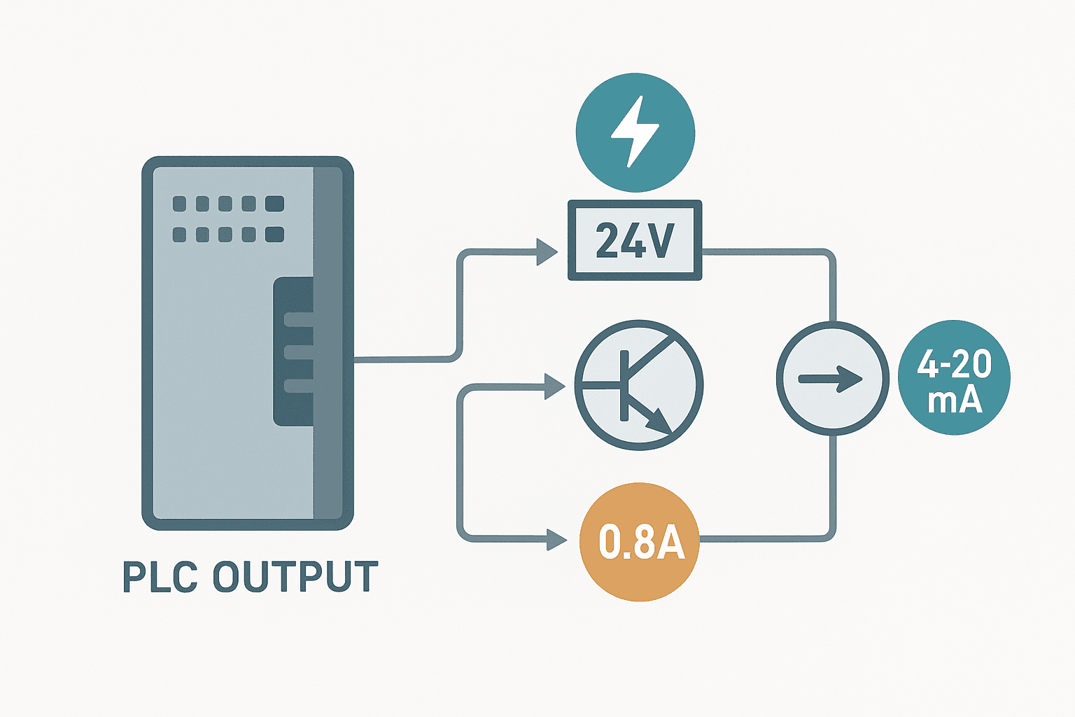
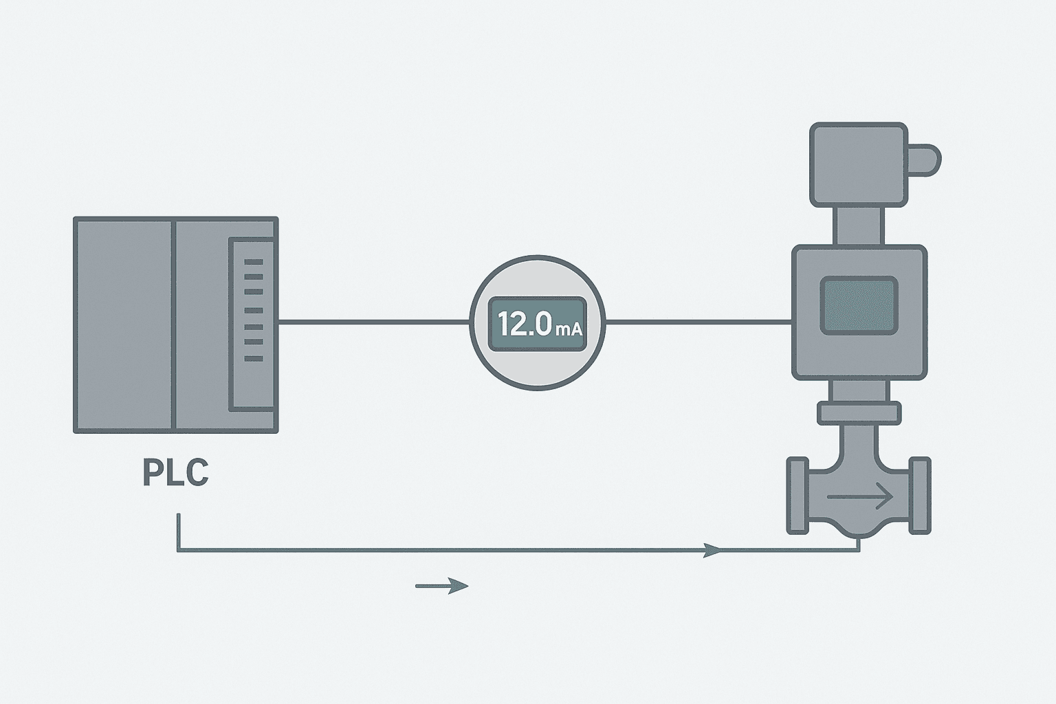
| 4-20 mA analog output | 4 to 20 mA measured inline | 0 mA or >20 mA (channel or loop fault) |
| 0-10 V analog output | 0 to 10 VDC vs analog common | Fixed voltage or 0 V (DAC failure) |
If the measurement at the terminal is correct but the load still does not respond, the fault is downstream: field wiring, connector, load device itself. If the measurement at the terminal is wrong with the supply confirmed good, the output channel has failed. At that point you are looking at a module replacement or, on modular systems, a channel-level spare swap.
Relay Output Faults: What to Look For
Relay output modules are rugged but they do fail, usually in one of three ways. First, the contact welds closed after an overload or motor inrush surge, so the output stays ON permanently. Second, the contact burns open and stops switching altogether. Third, the coil inside the relay fails and the contact never moves even though the logic drives it.
With power OFF and the channel de-energized, measure continuity across the relay output terminals. It should be open (no continuity). Then force the output ON and measure continuity again: it should now be closed (continuity). A welded contact shows continuity in both states. An open-circuit coil or failed contact shows no continuity in either state.
Relay outputs on most PLC modules are rated 2 A at 30 VDC or 240 VAC, with a lifetime of around 100,000 to 300,000 operations under load. Driving inductive loads like solenoids and motor starters without a suppression diode or snubber network burns through contacts fast. If you are replacing relay output modules repeatedly on a machine, add suppression at the load.
Transistor Output Faults: The Real Killers
Transistor (solid-state) outputs fail almost exclusively from inductive kickback or overcurrent. A solenoid valve or relay coil switched off without a flyback diode generates a voltage spike that can be 10 to 100 times the supply voltage for a microsecond. That spike blows the output FET, sometimes instantly, sometimes after months of gradual degradation.
A failed transistor output channel shows one of two signatures: the channel is permanently OFF (open FET) or permanently ON (shorted FET, which is the dangerous failure mode). If you have a shorted transistor output driving a solenoid, that solenoid energizes the moment you power the panel, regardless of logic. Always check for this when a machine starts behaving unexpectedly on power-up.
Understanding sinking vs sourcing wiring matters here too. A sourcing output that shorted internally will push 24 V to the load continuously. A sinking output that shorted will pull the load line to 0 V continuously. The failure symptom at the load looks different depending on the output type.
Analog Output Faults: Three Checks, In Order
Analog output faults fall into three categories: the wrong value being written, the correct value written but not reaching the device, and a genuine channel hardware failure.
- Check the raw value in the PLC. Go online and read the output register. A value of 0 when you expect 13,824 (50% of a 0-27648 Siemens range) tells you the logic is not writing the right value, not that the module is broken. Review your scaling code. See the 4-20 mA scaling formula if you need a reference.
- Measure actual current or voltage at the terminal. Use an inline mA meter for current loops (break the loop and insert the meter in series) or a voltmeter for voltage outputs. If the measured value matches what the PLC register says, the channel is working correctly and the problem is downstream.
- Check loop resistance for 4-20 mA outputs. Most PLC analog current output channels source into a maximum loop resistance of 300 to 600 ohms. If the total field wiring plus load impedance exceeds this, the output saturates below 20 mA. Measure total loop resistance with the loop de-energized.
PLC Output Fault Diagnosis on Specific Platforms
The sequence above works on any platform, but the diagnostic tools differ. On Siemens S7-1200 and S7-1500 in TIA Portal, navigate to Online and Diagnostics then I/O module status. The module will display channel-level fault bits and error codes. The Siemens PLC error codes guide covers what those codes mean in practice.
On Rockwell ControlLogix and CompactLogix, the Module Properties dialog in Studio 5000 shows channel-level fault and status data when you go online. The I/O tree in the controller organizer turns yellow or red for any module reporting a fault. On Mitsubishi MELSEC systems in GX Works3, the System Monitor view shows module error codes and individual channel status. On Omron Sysmac, Sysmac Studio provides a hardware diagnostics panel with similar channel-level detail.
From the Field: The Intermittent Relay Output That Was Not the Relay
I commissioned a packaging line where a labeller solenoid would randomly fail to fire, maybe twice per shift. The output LED on the module was fine, the relay was switching, and the fuse was good. The fault turned out to be a loose crimp on the return wire at the solenoid connector: just loose enough that thermal expansion during the day would open the circuit for a fraction of a second. The solenoid dwell time was only 80 ms, so we missed it on every random check. Clamping a data logger on the loop current caught it in thirty minutes. Intermittent output faults almost always live in connectors and crimps, not in the module itself.
That same diagnostic approach applies to intermittent sensor faults and is worth reading alongside this guide.
Output Fault Checklist
- Confirm the output bit is actually ON in the PLC software (not just assumed).
- Verify output common supply voltage at the module terminal strip.
- Check the bank fuse: measure voltage across it live.
- Force the output ON and measure voltage or current at the module terminal.
- If terminal reads correctly, trace the fault downstream through field wiring and connectors.
- If terminal reads incorrectly with supply confirmed, replace the module or channel.
- For analog outputs: verify the raw register value, measure actual loop current or voltage, check loop resistance.
- Check for inductive suppression on all transistor-output-driven coils.
- Review control panel grounding if multiple output channels fail without obvious cause: a floating common can cause strange multi-channel behavior.
- Remove all forces before returning the machine to production.
What to Read Next
Once you have resolved the output fault, it is worth building a broader troubleshooting picture. Start with PLC I/O fault diagnosis with a multimeter for the full input-side companion to this guide. Then read PLC CPU faults: how to diagnose them step by step to handle the cases where the module is fine but the controller itself is the problem. If your output drives a VFD, the VFD fault codes guide will help you interpret what the drive is reporting independently of the PLC output signal.
Frequently asked questions
How do I know if a PLC output module is faulty or if the load is faulty?
Can I force a PLC output without affecting the machine?
Why does my PLC show an output ON but the load does not energize?
How do I test a relay output on a PLC?
What causes a transistor PLC output to fail?
Why does a PLC analog output read the wrong value at the field device?
How do I find a blown fuse on a PLC output module?
Can a PLC output fault cause the CPU to go into fault mode?
What is the difference between a short-circuit-protected output and a standard output?
How do I troubleshoot an analog output that reads correctly in the PLC but the actuator does not respond?
Now build it
You have just read about XIC and XIO. Reading a rung and making one behave are different skills, and the second one is the job.
Start / Stop Circuit
Beginnerabout 10 minThe first circuit every controls engineer learns: a motor that starts on a button press, keeps running when the button is released, and stops on a stop button, with stop always winning.
Build this rungFree, no signup, runs in your browser. See all 16 exercises.
Was this helpful?