GX Works3: A Practical Getting-Started Guide
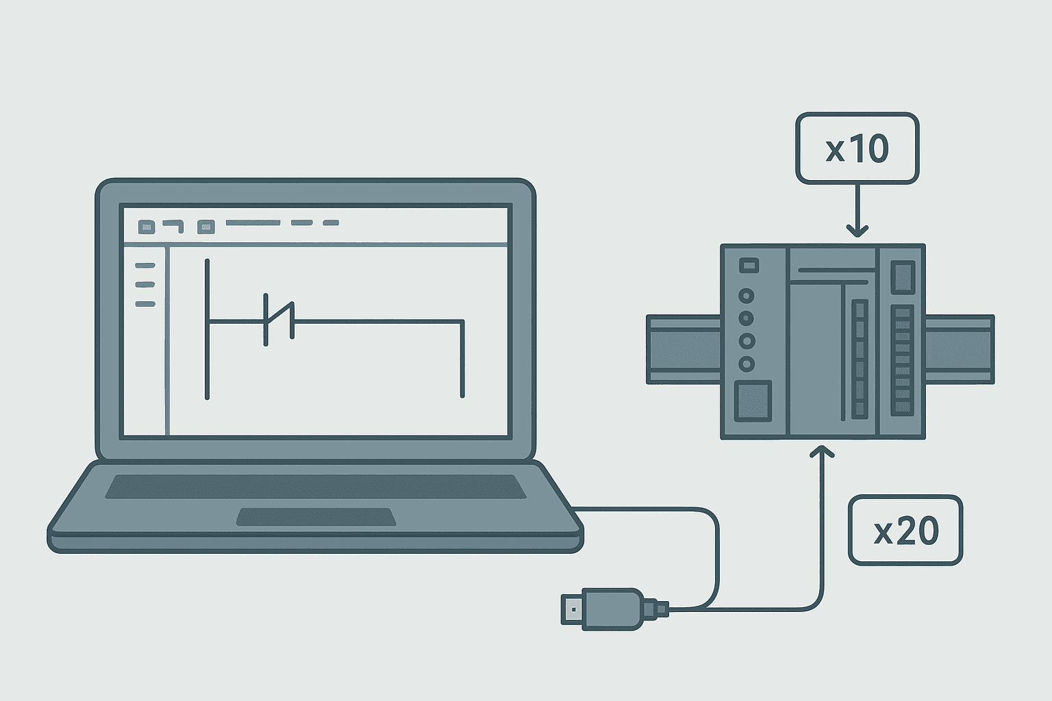
GX Works3 is Mitsubishi Electric's programming environment for the iQ-R and iQ-F (FX5) PLC families. If you have used GX Works2 on MELSEC-Q projects, the workspace will feel familiar but the internals are different enough that you will hit a few surprises on your first iQ-R job. This guide gets you from installation to a running program, with the specific menus, device addresses and gotchas that actually matter on the bench.
What Is GX Works3?
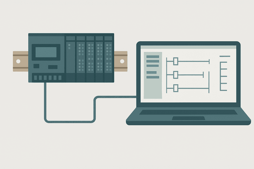
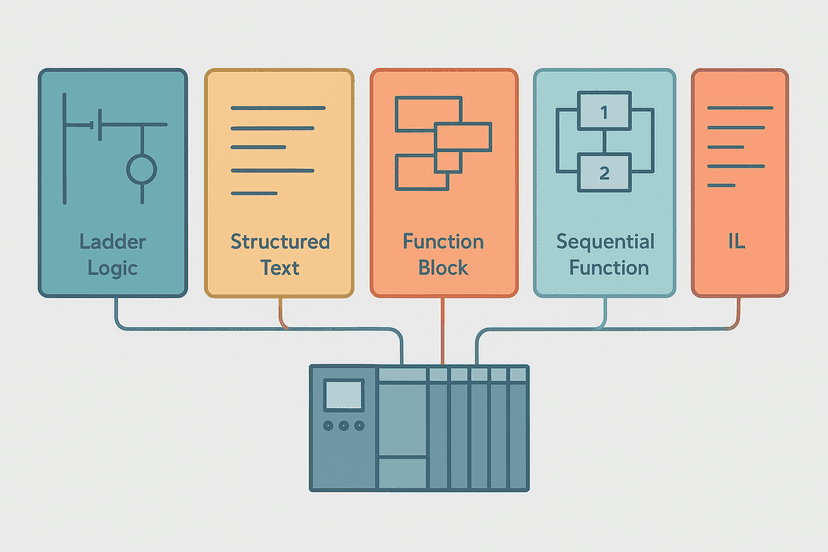
GX Works3 is the integrated development environment (IDE) Mitsubishi Electric provides for programming, configuring, simulating and monitoring MELSEC iQ-R series and MELSEC iQ-F (FX5U, FX5UC, FX5UJ) PLCs. A single installation handles ladder diagram, structured text, function block diagram, IL and SFC under IEC 61131-3, plus hardware module configuration, network parameter setup and online diagnostics. It replaces GX Works2 for those newer platforms but does NOT support MELSEC-Q or FX3 hardware; for those you still need GX Works2.
Installation and Licensing
The product ID you need is SW1DND-GXW3. Mitsubishi distributes GX Works3 through their FA Global website and through authorised distributors. The installer is large (around 5 GB unpacked), so give it time. A 30-day trial mode is available if you launch without activating a license: you can write programs and run the simulator, but writing to physical hardware is blocked.
On a Windows 10 or 11 machine, install as administrator. The software uses a USB driver (MELSEC USB driver) for CPU-direct connections. That driver installs automatically, but if your USB port shows an unknown device afterward, open Device Manager, right-click and point it to the driver folder inside the GX Works3 install directory, typically C:\Program Files (x86)\MELSOFT\Easysocket.
Creating Your First GX Works3 Project
Open GX Works3 and choose Project, New. The first dialog asks for three things: Series (iQ-R Series or iQ-F Series), CPU type (for example, R04CPU or FX5U-32MT/ES), and language (Ladder, ST, etc.). Get the CPU type right here. Picking R04CPU when your hardware is an R08CPU is not a disaster during programming, but parameter mismatches will cause a write error at transfer time.
The project tree on the left lists Program, Global Labels, Device Comments and Parameter. For most ladder work you will spend your time in Program, under Main (which maps to OB1 in Siemens terms or the main task in other IEC environments). Double-click Main under POU to open the ladder editor.
Device Addresses: What X, Y, M and D Actually Mean
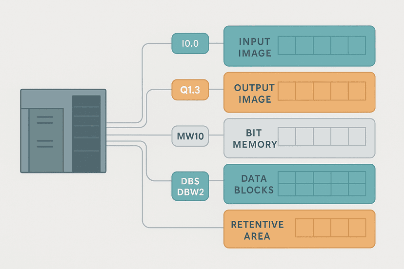
Mitsubishi uses a device-based addressing scheme rather than a symbolic tag database like TIA Portal. Understanding this is critical before you write a single rung. The key devices for iQ-F are shown below. Note that X and Y addresses are octal, not decimal: X0 to X7 is eight inputs, then X10 to X17 is the next eight. There is no X8 or X9.
| Device | Type | Typical use | Address range (FX5U-32MT) |
|---|---|---|---|
| X | Input relay (physical) | Digital inputs from field | X0 to X17 (16 pts, octal) |
| Y | Output relay (physical) | Digital outputs to field | Y0 to Y17 (16 pts, octal) |
| M | Internal relay (bit) | Flags, latches, intermediate logic | M0 to M7679 |
| T | Timer | TON-style delay, coil + contact | T0 to T511 |
| C | Counter | Up counter, 16-bit | C0 to C199 |
| D | Data register (word) | Integer values, setpoints, scaling | D0 to D7999 |
If you are coming from a Rockwell or Siemens background, the concept of PLC memory and addressing is the same at heart, but the octal input/output numbering trips people up every time. I have seen experienced integrators wire the ninth input to X10, then spend twenty minutes wondering why it does not show up in the rung they wrote for X9. X9 does not exist.
Writing Ladder Logic in GX Works3
The ladder editor works on a row-by-row basis. To insert a normally open contact (equivalent to XIC in Rockwell or a standard contact in IEC), press F5 or click the contact icon in the toolbar, then type the device address (e.g. X0) and press Enter. For a normally closed contact, press F6. For an output coil, press F7. The logic is the same as any other ladder environment; see XIC vs XIO contacts explained if you want a refresher on contact types.
Parallel branches (OR logic) are added with Shift+F5 for a parallel open contact. You draw the branch below the existing rung and GX Works3 automatically connects it. This is slightly different from TIA Portal's drag-and-drop approach but faster once you learn the shortcuts.
GX Works3: Conveyor Start with Proximity Sensor Enable and E-Stop Guard. Ladder logic (5 rungs): Rung 0: examine if X0 is on (XIC), then either examine if M10 is on (XIC), then examine if X5 is off (XIO), then examine if M20 is off (XIO), then energize output Y0 (OTE). Rung 1: examine if Y0 is on (XIC), then energize output M10 (OTE). Rung 2: examine if Y0 is on (XIC), then examine if X3 is off (XIO), then TON on T0. Rung 3: examine if T0.DN is on (XIC), then examine if M21 is on (XIC), then latch output M20 (OTL). Rung 4: examine if M20 is on (XIC), then examine if X6 is on (XIC), then examine if Y0 is off (XIO), then unlatch output M20 (OTU). X0 = Start PB, X3 = Run feedback (NC), X5 = E-stop (NC), X6 = Fault reset PB. Y0 = Conveyor drive output, M10 = Seal-in latch, M20 = Run-confirm fault latch, M21 = one-shot. T0 monitors for missing run-confirm: if Y0 is on but X3 never closes within 5 seconds (K50 x 100 ms), a fault latches in M20 and drops Y0. Pressing X6 while stopped clears the fault.
The diagram above evaluates one scan. Run these exact rungs on a real scan cycle to watch the latching and the timers behave.
Run this in the simulatorTimers in GX Works3 ladder use the OUT T instruction. T0 through T199 on the FX5U default to 1 ms resolution; T200 onward default to 100 ms. The preset is set with a K constant (K50 = 50 x the resolution). You can also reference a D register as the preset for adjustable setpoints. This is the same pattern you would use when understanding TON, TOF and TONR timers on other platforms.
Compiling and Transferring to Hardware
Before writing to the PLC you must compile. Go to Convert, then Convert (or press F4). The output window at the bottom shows any errors. Common ones include an unrecognised device address (usually a typo like X9), a missing END instruction, or a label conflict in structured text. Fix them all before proceeding.
To connect, go to Online, Current Connection Destination. Select USB for a direct CPU connection, then click Connection Test. If it fails, check the USB driver and confirm the CPU is powered. Once connected, go to Online, Write to PLC. The dialog breaks the transfer into Program Data, Parameter, and Device Comment. For a first write, check all three. Put the CPU in STOP mode first (the RUN/STOP switch on the CPU front) or GX Works3 will prompt you to do it remotely.
Online Monitoring and Device Watch
Once the program is running, go to Online, Monitor, Monitor Mode (or press F3). Contacts that are energised turn blue (the default colour scheme), coils that are on show filled. This is standard ladder monitoring and works exactly as you would expect from PLC troubleshooting using online monitoring.
For watching specific devices, open the Device/Buffer Memory Batch Monitor from the View menu. Type in a starting device (D0 for example) and it shows a live table of that device and the next several in sequence. For bit devices, each cell shows 0 or 1. For word registers, the value is shown in decimal by default; right-click to switch to hex or binary. This is invaluable when debugging analog input scaling that is writing values into D registers.
You can also force device states from monitor mode. Right-click a device and choose Forced Input/Output Registration. This lets you set a bit on or off, or write a value to a D register, without changing the program. Use this carefully: a forced bit does not mean the physical input changed, so testing PLC inputs properly still requires a multimeter on the terminal.
Module Parameters: Getting I/O and Comms Right
Unlike GX Works2, GX Works3 uses a module configuration wizard under Parameter, Module Configuration. You drag CPU and I/O modules onto the rack diagram and set properties per module. For iQ-F, the built-in I/O is configured under the CPU parameters directly. This is where you set the input filter time (the default is 10 ms, which is fine for most push buttons but too slow to catch high-speed pulses from encoders), the output type, and the RS-485 settings for Modbus RTU communication.
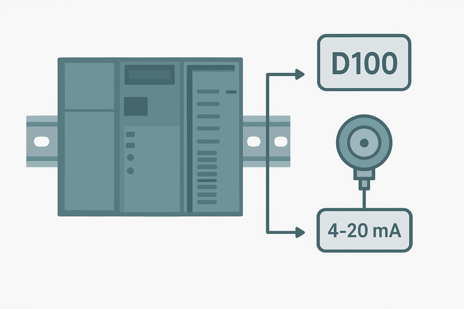
For analog expansion modules on iQ-F (FX5-4AD, FX5-4DA), the module configuration wizard lets you set channel range (0-10 V, 4-20 mA, etc.) without writing any special initialisation rungs. That is a big improvement over FX3 series, where you had to write FROM/TO instructions to configure analog channels. The raw value lands in a buffer memory address that you read with the MOV instruction into a D register, then scale. For the scaling maths, the 4-20 mA scaling formula guide covers the arithmetic directly.
Simulation Without Hardware
GX Works3 ships with a built-in simulator for iQ-R and iQ-F. Compile your project, then go to Debug, Simulation, Start Simulation. The simulator opens a virtual CPU and you can enter monitor mode immediately. Bit devices can be toggled by double-clicking them in the ladder view. Timer and counter presets count down in real time. The simulator is not cycle-accurate for precise timing tests, but it is good enough to prove out logic flow before you are at the machine. For a broader look at options, how to simulate ladder logic without PLC hardware covers what each vendor's simulator can and cannot do.
Three Field Gotchas Worth Knowing
- Octal addressing bites everyone once. X7 is the eighth input. The ninth is X10. Write it on the panel door if you have to.
- Battery backup on iQ-R CPUs is not fitted by default. The R04CPU takes an optional Q6BAT battery. Without it, retentive M and D devices lose their values on power cycle. Check your retention requirements before commissioning.
- GX Works3 does not auto-save. Set an autosave interval under Tool, Options, Project, or you will regret a crash during a long session. I lost 45 minutes of work on a food-processing line because I assumed it behaved like TIA Portal.
Keep Learning
GX Works3 covers a lot of ground: structured text, function blocks, motion with iQ-R motion CPUs, CC-Link IE Field network setup. Once your ladder basics are solid, structured text is worth learning for data manipulation and scaling; structured text in TIA Portal shows the same concepts in a Siemens context that translate directly. For a comparison of how other vendor IDEs are structured, the Omron Sysmac Studio getting-started guide and the Keyence KV Studio guide make good parallel reading.
Frequently asked questions
What PLCs does GX Works3 support?
Is GX Works3 free to download?
How do I connect GX Works3 to a Mitsubishi PLC?
What device addresses does GX Works3 use for inputs and outputs?
Can I simulate a GX Works3 program without hardware?
What is the difference between GX Works2 and GX Works3?
How do I write a program to the PLC in GX Works3?
What scan cycle monitoring tools does GX Works3 have?
How do I add a timer in GX Works3 ladder logic?
Can GX Works3 read and write Modbus RTU?
Now build it
You have just read about XIC and XIO. Reading a rung and making one behave are different skills, and the second one is the job.
Start / Stop Circuit
Beginnerabout 10 minThe first circuit every controls engineer learns: a motor that starts on a button press, keeps running when the button is released, and stops on a stop button, with stop always winning.
Build this rungFree, no signup, runs in your browser. See all 16 exercises.
Was this helpful?