Mitsubishi PLC Error Codes: How to Read and Fix Them
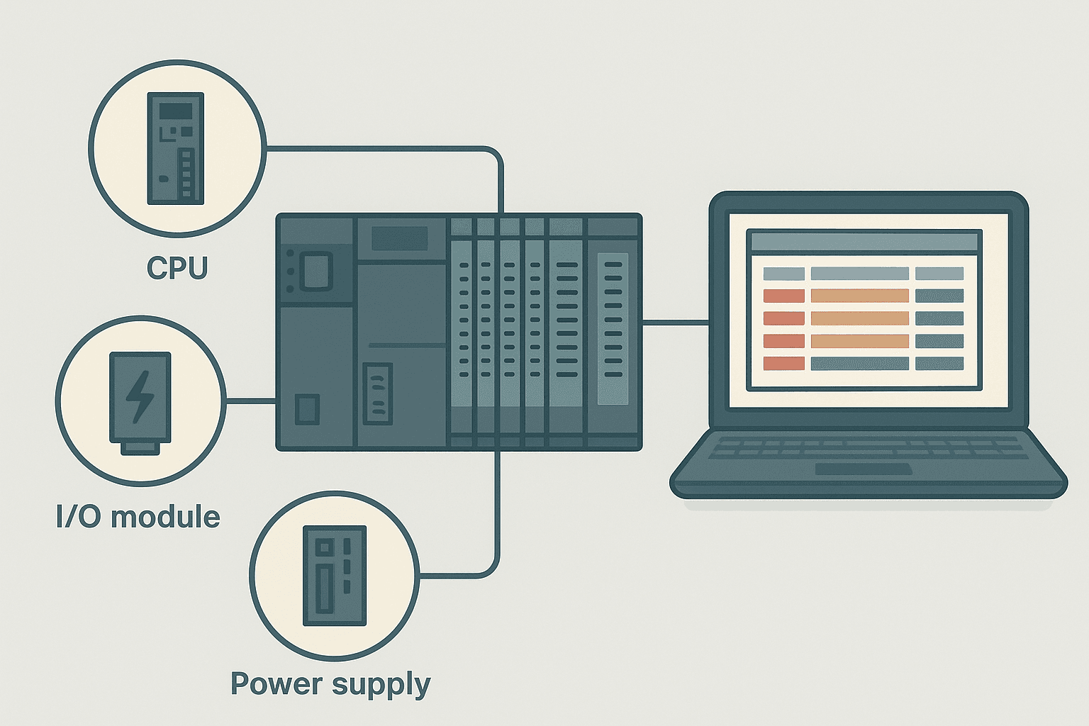
Your Mitsubishi MELSEC PLC has stopped, the ERR LED is on, and production is waiting. The error code staring back at you from the CPU front panel is a four-digit number you have never seen before. That number is not random: it is a structured diagnostic code that tells you exactly what failed and, in most cases, where to look first. This guide shows you how to read those codes in GX Works3, what the major code groups mean, and the practical steps to clear the most common faults.
What Are Mitsubishi PLC Error Codes?
Mitsubishi PLC error codes are four-digit hexadecimal or decimal values stored in the CPU's error history buffer whenever the CPU detects a fault condition. Each code maps to a specific error class (major or minor), a plain-language description, and a set of corrective actions defined in the CPU user manual. You read them through GX Works3 System Monitor or via the front-panel display, and they remain logged even after a power cycle so you can review what happened before you arrived on site.
How to Read Mitsubishi PLC Error Codes in GX Works3
If you are new to the Mitsubishi software environment, the GX Works3 getting-started guide covers installation and basic navigation. Once you are connected:
- Connect to the CPU via USB (mini-B on most iQ-R CPUs) or Ethernet. Make sure the project on the PC matches the CPU type.
- Go to Diagnostics > System Monitor (or press F8 in GX Works3).
- Click the Error Information tab. You will see a list of active and historical errors with code, description, time stamp and program step.
- Click any entry to expand it. GX Works3 shows the error class (major/minor/warning), the module that reported it, and a Jump to Error button.
- Use Jump to Error to land on the exact rung or step in the ladder or ST program where the fault was detected.
- Check the Module Diagnostics tab for any intelligent function module or I/O module faults logged separately from the CPU.
Mitsubishi PLC Error Code Groups: The Structure
MELSEC iQ-R and Q-series error codes follow a structured numbering scheme. Knowing the group tells you immediately which subsystem to investigate. The FX5U uses the same broad groupings but with different individual code values, so always confirm in your specific CPU manual.
| Code Range | Category | CPU Behaviour |
|---|---|---|
| 1000-1999 | CPU hardware faults (RAM, ROM, ASIC) | CPU stops (major) |
| 2000-2999 | Program memory / file faults | CPU stops (major) |
| 3000-3999 | Scan / watchdog / execution faults | CPU stops (major) |
| 4000-4999 | Parameter or configuration mismatch | CPU stops or continues (major/minor) |
| 5000-5999 | Intelligent function module faults | CPU continues (minor) |
| 9000-9999 | Battery and clock faults | CPU continues (warning) |
The Most Common Mitsubishi PLC Error Codes and How to Fix Them
Error 2100: Program Memory Checksum Fault
This one hits hardest because the CPU will not run at all. The stored program data has failed its checksum verification, which almost always happens after a power interruption mid-write or a failing internal flash memory. The fix: verify the project in GX Works3 (no errors on the PC side), clear PLC memory with the Clear PLC Memory function, then re-download the project in full. If the error returns immediately after a fresh download, the CPU internal memory is failing and the module needs replacing. I have seen this twice on Q06UDEH CPUs that had been power-cycled hundreds of times per day in a cycling furnace application.
Error 3000: Watchdog Timeout
The scan cycle ran longer than the watchdog timer value. The default is 200 ms on most iQ-R CPUs. The usual culprits are a FOR-NEXT loop with a very high iteration count, a large string manipulation block, or a slow file register access to an SD card. Check the scan time in GX Works3 (Diagnostics > Scan Time Monitor) while the machine is running at full load. If average scan time is below 50 ms but you are still getting 3000 errors, look for a specific condition that triggers a long branch. You can also increase the watchdog value in the CPU parameter settings under System Parameter, but treat that as a diagnostic tool, not a permanent fix. Fix the scan problem first. This ties directly into the broader topic of PLC scan cycle problems.
Error 4000: Operation Error (Divide by Zero / Out-of-Range)
Error 4000 is a runtime arithmetic error: most commonly a divide-by-zero, an out-of-range BCD conversion, or an indirect address that points outside the valid device range. GX Works3 will show you the exact step number. Jump to Error and look at what the divisor or the index register holds at the moment of fault. Add a guard condition (check the divisor is not zero before the DIV instruction) and the error disappears. On PLC memory and addressing, index registers are a common source of 4000 errors when they are not initialised before use.
Error 4100: Module Verify Error
The physical module configuration does not match what is stored in the CPU parameters. This happens after a module swap, a slot change, or restoring a project from a machine with a different hardware build. Go to GX Works3, open the System Parameter, and use Verify with PLC to identify the mismatch. Correct the parameter to match the actual hardware, write the system parameter to the CPU, and power cycle. Do not try to just clear the error without fixing the parameter file: it will come straight back.
Error 5000-Series: Intelligent Function Module Faults
These codes are generated by analog I/O modules, positioning modules, communication modules and similar devices. The CPU itself keeps running, but the module has detected something wrong. Common causes include an open-wire on an analog channel (which shows as a channel error in the Module Diagnostics tab), a hardware fault in the module itself, or a parameter mismatch. If you are chasing an analog module fault, the PLC analog input wiring guide covers the most common wiring mistakes that trigger channel faults on MELSEC analog modules, and the 4-20 mA scaling formula guide covers the buffer memory addresses used to read raw counts.
Error 9000 / Battery Low Warning
This is a warning, not a stop fault, but do not ignore it. The backup battery that retains data memory and the clock is running low. On iQ-R CPUs the battery type is Q6BAT. On older Q-series it is Q7BAT. Replace it while power is on to avoid losing retentive data. After replacement, clear the battery error flag in GX Works3 and confirm the system clock is still correct. If the CPU has already lost power with a dead battery, check your retentive data areas (latch relays, data registers) for corruption before restarting the machine.
FX5U-Specific Error Codes: What Is Different
The FX5U compact PLC shares the same broad error category logic as the iQ-R but uses a seven-segment display on the front panel that scrolls through a condensed code. A blinking ERR LED with the display showing 'E' followed by a three-digit number is the normal presentation. Some codes unique to the FX5U include:
- Error 1610: Built-in Ethernet port hardware fault. Check the port physically and verify IP settings in GX Works3 under Module Parameter > Ethernet Port.
- Error 2200: File register parameter area checksum error. Re-write the parameter from GX Works3.
- Error 3210: Interrupt program execution time exceeded. Check the interrupt interval setting and the code inside the interrupt routine for length.
- Error 4010: Device out of range in a TO/FROM instruction accessing a special function module. Check index register values.
Step-by-Step Diagnosis Workflow
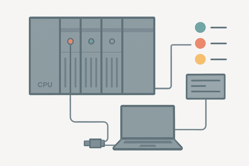
- Note the CPU LED state: RUN (green), ERR (red), BAT (yellow). A solid ERR with no RUN means a major fault stop. A flashing ERR with RUN still on is a minor or continuation error.
- Read the front-panel display code for a quick category reference.
- Connect GX Works3 and open Diagnostics > System Monitor. Record every active error: code, step, time stamp.
- Click Jump to Error for 3000 and 4000 series codes to go directly to the offending rung.
- Check Module Diagnostics for any 5000-series module faults. Note the module number and channel.
- Fix the root cause: correct the program, re-write parameters, replace hardware, or fix wiring.
- Clear the error via Diagnostics > Reset CPU Error or the key switch RESET position.
- Power cycle if the error requires it, then confirm the CPU returns to RUN with no active errors.
- Test the machine under normal operating conditions and monitor the scan time and error log for 10 minutes before handing back.
For general techniques that apply across all platforms, PLC troubleshooting with online monitoring and PLC I/O fault diagnosis with a multimeter are worth reading alongside this guide. If your Mitsubishi system has a communication module involved, also check whether the fault is actually on the network side: PROFINET communication loss diagnosis covers the steps for MELSEC CPUs using PROFINET intelligent modules.
Mitsubishi PLC Error Codes vs Siemens and Omron: A Quick Comparison
All three platforms use structured error codes, but the diagnostic interface differs. Siemens TIA Portal surfaces faults in the Diagnostics buffer and device status pages (see Siemens PLC error codes guide for the detail). Omron uses the Controller Status tab in Sysmac Studio and a separate error table in CX-Programmer (covered in the Omron PLC error codes guide). Mitsubishi's advantage is the time-stamped error history that survives a power cycle, which makes post-mortem analysis on intermittent faults much easier. The workflow of: read the code, jump to the offending step, fix root cause, clear and verify, is consistent across all three platforms even if the exact menu paths differ.
Preventing Recurring Errors: Three Practical Habits
- Guard every division instruction with a zero-check condition upstream. A single XIO(Divisor_Is_Zero) contact before the DIV block prevents 4000 errors permanently.
- Set the watchdog value to roughly three times your measured peak scan time, not the default 200 ms. Review scan time after every major program change.
- Add a battery replacement reminder to the annual PM schedule. A Q6BAT costs less than five minutes of downtime and lasts roughly five years at 25 degrees C ambient.
If you are also seeing faults from drives connected to the MELSEC system, the VFD fault codes troubleshooting guide covers how to interpret drive-side codes that often appear alongside PLC errors in a coordinated fault chain. And if PLC output faults or PLC power supply faults are part of the picture, those guides cover the hardware side that error codes alone do not tell you.
What to Read Next
Now that you can read and clear Mitsubishi MELSEC error codes, the next step is building a repeatable troubleshooting process that works for any fault, not just the ones with obvious codes. Start with PLC CPU faults: how to diagnose them step by step for a systematic approach, then review PLC troubleshooting interview questions to pressure-test your diagnostic reasoning. If you want to deepen your Mitsubishi-specific knowledge, the GX Works3 getting-started guide covers the tool features you need for confident online diagnosis.
Frequently asked questions
How do I read error codes on a Mitsubishi MELSEC PLC?
What does Mitsubishi PLC error code 3000 mean?
What is error code 2100 on a Mitsubishi PLC?
How do I clear a fault on a Mitsubishi MELSEC PLC?
What does error 4100 mean on a Mitsubishi iQ-R?
Can a Mitsubishi PLC run with a minor error active?
What causes a Mitsubishi PLC battery error and how do I fix it?
How do I find which rung caused an operation error in GX Works3?
What is the difference between a CPU error and a module error on MELSEC?
Do Mitsubishi FX5U error codes differ from iQ-R codes?
Now build it
You have just read about XIO. Reading a rung and making one behave are different skills, and the second one is the job.
Start / Stop Circuit
Beginnerabout 10 minThe first circuit every controls engineer learns: a motor that starts on a button press, keeps running when the button is released, and stops on a stop button, with stop always winning.
Build this rungFree, no signup, runs in your browser. See all 16 exercises.
Was this helpful?