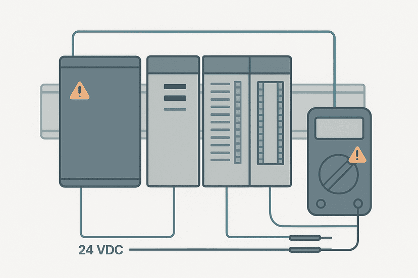
PLC Communication Faults: How to Diagnose Them
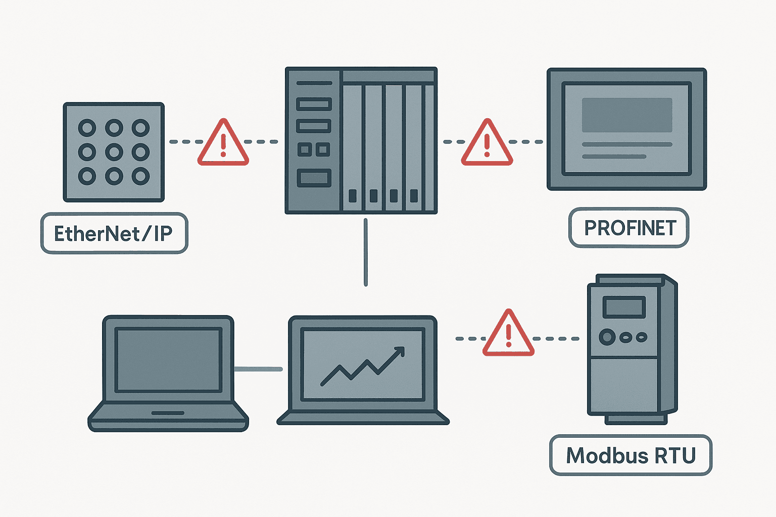
A communication fault can look like almost anything: outputs stuck on, HMI screens gone blank, a VFD ignoring speed references, or an entire remote I/O rack going dark. The PLC is running, the program is fine, but the data is not moving. These faults are frustrating because the symptom is rarely at the same location as the cause.
What Are PLC Communication Faults?
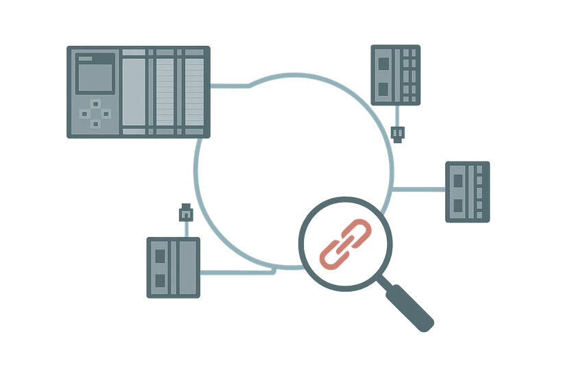
PLC communication faults occur when a data exchange between a PLC and another device (a remote I/O module, HMI, drive, another PLC, or a SCADA server) fails or times out. The PLC cannot read inputs or write outputs on the affected connection, and it sets a fault status bit or goes into a connection-lost state. The root cause can be physical (cable, connector, switch), configuration (IP address, baud rate, node address), or timing (network load, watchdog timeout too tight).
Start Here: Confirm What Is Actually Faulted
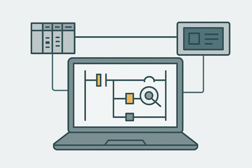
Before you touch a single cable, connect your laptop and go online. The programming software will tell you more in 30 seconds than an hour of physical inspection. In Studio 5000 open the I/O tree: a yellow triangle means a connection warning, a red X means the connection is lost. In TIA Portal look at the device diagnostics under Online and Diagnostics. Both tools will show you exactly which device is faulted and a fault code. Write it down.
The PLC Troubleshooting with Online Monitoring post covers this first-contact diagnostic step in detail. Once you know which device is offline, you can work outward from the PLC toward that device, not the other way around.
PLC Communication Fault Diagnosis by Network Type
EtherNet/IP: The Most Common Culprits
EtherNet/IP runs over standard TCP/IP hardware, which means all the usual IT network problems apply. The single most common fault I see in the field is a duplex mismatch: the PLC port is set to auto-negotiate and the switch port is hard-coded to 100 Mbps full duplex, or vice versa. The link comes up but you get late collisions and CRC errors, and the connection times out randomly. Always hard-code both ends to the same speed and duplex, or leave both on auto.
IP address conflicts are the second most common cause. Two devices with the same address will fight each other and both will appear intermittently offline. Run a quick ping sweep or open Advanced IP Scanner before you assume the cable is bad. For a deeper look at how EtherNet/IP connections are established, EtherNet/IP Scanner vs Adapter: How It Works explains the scanner/adapter model and what the connection parameters actually mean.
- Check the link LED on the switch port and the device port. No link = cable or SFP fault.
- Ping the device from a laptop on the same subnet. No reply = IP config or routing problem.
- Check the switch port statistics for CRC errors, runts or late collisions. Any non-zero count = duplex mismatch or bad cable.
- Confirm the RPI (requested packet interval) is not too aggressive for the network load. 10 ms RPI across a busy switch will cause timeouts.
- If the device is a drive, check whether the drive's Ethernet port has its own IP set correctly. VFD Parameters Explained covers the network parameters you need to verify.
PROFINET: Device Name and IP Mismatches
PROFINET adds a layer of complexity that EtherNet/IP does not have: the device name. Every PROFINET device must have a name that matches the one configured in the project. When you replace a remote I/O head station or a drive, the new hardware arrives with a blank name. The PLC will not connect to it until you assign the correct name using your programming tool or a PROFINET scanner.
The PROFINET Communication Loss: How to Diagnose It post goes deep on this, including how to use TIA Portal's device diagnostics to read the exact alarm. For the physical layer side, PROFINET Wiring: Cables, Connectors and Topology covers the cable spec differences between PROFINET Cat 5 and standard Cat 5e that bite people on long cable runs.
Modbus RTU: Serial Settings Must Match Exactly
Modbus RTU is unforgiving about configuration. If the baud rate on the master is 19200 and the slave is 9600, you get nothing. Not errors, nothing. The master times out and reports a no-response fault. Always verify baud rate, data bits (almost always 8), stop bits (1 or 2), and parity (none, even or odd) on both ends before assuming a hardware problem.
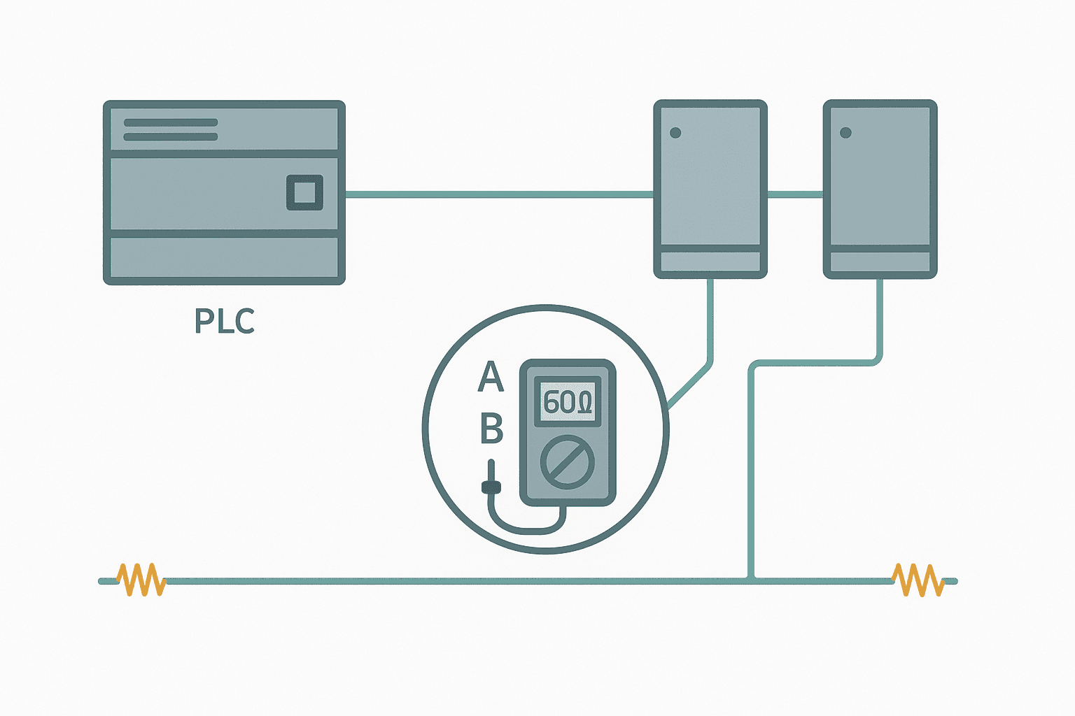
The physical side matters too. RS-485 needs exactly two termination resistors: one at each end of the bus, typically 120 ohms. A missing terminator causes signal reflections that corrupt frames at high baud rates. An extra terminator on a T-junction drops the line impedance and causes the same problem. Measure the resistance between A and B with all devices powered off: you should read around 60 ohms (two 120-ohm resistors in parallel). For protocol details, Modbus RTU Protocol Explained: Frames, Timing and Wiring is the reference to keep open.
Physical Layer Checks That Get Skipped
I have been on commissioning jobs where a brand-new Ethernet cable was the fault. The cable tested fine with a basic continuity tester but failed a proper certification test because pin 3 and pin 6 were swapped (a crossover pair). That cable would sync at 10 Mbps but fail at 100 Mbps. Always use a proper cable tester, not just a continuity checker, when you are chasing an intermittent fault.
For serial networks the cable quality matters even more. Unshielded cable run alongside 480 VAC motor wiring picks up enough noise to corrupt frames. The Shielding Analog Signal Cables in PLC Panels post applies equally to RS-485 cables: shield the cable and ground the shield at one end only. Also check that the cable shield is not creating a ground loop, which the Control Panel Grounding: The Right Way to Do It post covers properly.
A Systematic Fault-Finding Table
| Symptom | Most Likely Cause | First Check |
|---|---|---|
| No link LED on switch or device | Faulty cable or failed port | Swap cable, try a different switch port |
| Link LED on but connection times out | Duplex mismatch or RPI too tight | Check switch port stats for CRC errors, adjust RPI |
| PROFINET device fault after replacement | Device name not assigned | Assign device name via TIA Portal online tools |
| Modbus RTU no response on any slave | Baud/parity mismatch or missing terminator | Check settings both ends, measure A-B resistance |
| Intermittent comms loss, no clear pattern | Loose connector or EMI | Reseat all connectors, log fault times vs machine events |
When the PLC Goes to Fault Because of a Comms Loss
A communication fault does not always stop the PLC, but it can if the connection is configured as required (or inhibited in Rockwell terminology is the opposite: it tells the PLC to ignore that device). In TIA Portal the equivalent is the organization block OB86, which runs on rack/station failure. If you have not written any code in OB86, the CPU will go to STOP when a PROFINET device drops out.
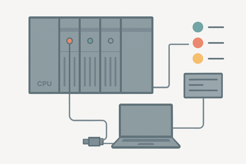
The right approach is to handle comms faults in logic: check the connection status bit, set an alarm, and put the affected outputs into a known safe state. Do not rely on the CPU going to STOP as your safety mechanism. The PLC CPU Faults: How to Diagnose Them Step by Step post explains how to read the CPU diagnostic buffer to separate a comms-induced CPU fault from a genuine program fault.
HMI and SCADA Communication Faults
HMI communication faults are slightly different because the HMI is usually a passive client: the PLC does not care if the HMI is offline. But the HMI will show stale data or tag errors, which operators misread as a machine fault. Check the HMI tag connection status first. HMI Tag Linking: Mapping PLC Addresses Correctly explains how tag addresses get mapped, and a single wrong address or wrong data type will cause a communication error on that tag without affecting the rest of the connection.
For SCADA systems the same applies. If your SCADA historian is polling too aggressively, it can saturate the PLC's Ethernet port and cause legitimate control connections to time out. Spread your poll rates and use a dedicated SCADA network port where the hardware supports it. SCADA Communication Protocols: Modbus, DNP3 and OPC UA covers how to tune poll rates per protocol.
Drive Communication Faults
Drives add one more failure mode: the drive's own watchdog. Most drives have a configurable comms timeout. If the PLC does not send a valid command word within that timeout, the drive trips on a comms fault. This is a safety feature, not a bug. But if the timeout is set too short (some drives default to 100 ms), a brief network hiccup will trip the drive even though the PLC recovered. Set the drive comms timeout to at least 3 to 5 times your RPI or scan time, and make sure the PLC program sends a valid command word every scan. The VFD Fault Codes: What They Mean and How to Fix Them post has a section on network-related fault codes for common drive families.
Using the PLC I/O Fault Diagnosis Tools You Already Have
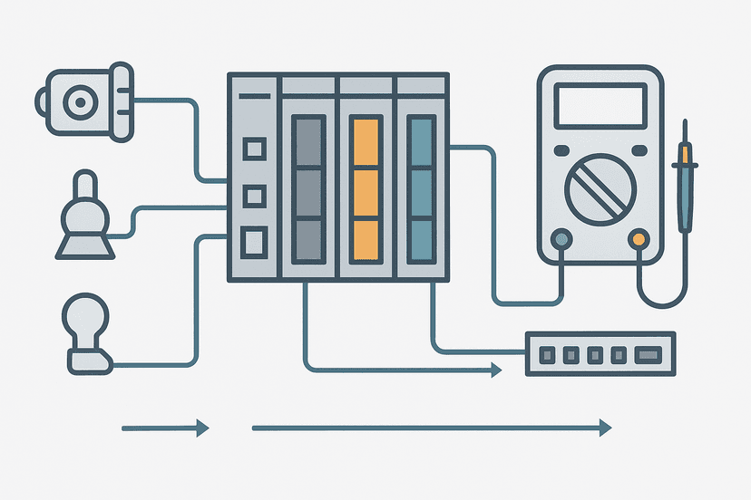
You do not need expensive network analyzers for most PLC communication faults. Your programming software, a laptop with Wireshark, and a basic cable tester cover 90% of cases. For the physical layer, PLC I/O Fault Diagnosis with a Multimeter covers the voltage and resistance checks that apply to both digital I/O and serial comms wiring. And if you are not sure whether the fault is in the field wiring or the PLC module itself, the Types of PLC Modules: I/O, Comms and More post explains what each module type does and what its failure modes look like.
For intermittent faults that disappear before you can catch them, set up data logging in your programming software. Studio 5000 has a trending tool; TIA Portal has the trace function. Log the connection status bit and any relevant process values. Intermittent communication faults almost always have a pattern once you have 20 or 30 occurrences logged. The Intermittent Sensor Faults: How to Find Them post covers this logging approach for sensor faults, and the same technique works for comms faults.
Keep Learning
Communication faults rarely exist in isolation: a power supply sag can take down a network switch, and a CPU fault can look exactly like a comms fault until you read the diagnostic buffer. Work through PLC Power Supply Faults: How to Diagnose Them to rule out power as the root cause, and use PLC Troubleshooting with Online Monitoring to set up the software-side monitoring that catches faults before they become production stops. If the fault is specific to PROFINET, PROFINET Communication Loss: How to Diagnose It goes into greater depth on that protocol.
Frequently asked questions
What causes a PLC communication fault?
How do I know if my PLC has a communication fault?
What is the first thing to check on a PROFINET communication fault?
Can an IP address conflict cause a PLC communication fault?
How do I diagnose a Modbus RTU communication fault?
Why does my PLC lose communication only at certain times of day?
What tool do I need to troubleshoot PLC Ethernet communication faults?
How do I reset a communication fault on a remote I/O module?
Does a communication fault put the PLC in fault mode?
What is the difference between a communication fault and a CPU fault?
Learn this by building it
There is a PLC in this site. It runs a real scan engine, checks your logic against the same tests a working machine would fail, and needs no download and no account.
Open the exercisesFree, no signup, runs in your browser. See all 16 exercises.
Was this helpful?