PLC Digital Input Faults: How to Diagnose Them
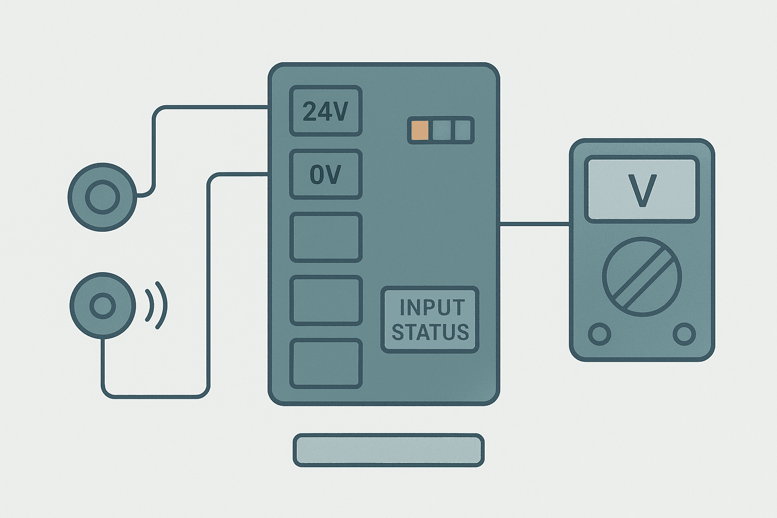
A PLC digital input fault is one of those problems that can waste an entire shift if you chase it in the wrong order. The machine stops, the operator says a sensor is faulty, you swap the sensor, and the fault comes back 20 minutes later. Sound familiar? The real culprit is almost never the sensor itself. It is usually a wiring issue, a grounding problem, noise, or a subtle mismatch between the sensor output type and the module's input circuit.
What Is a PLC Digital Input Fault?
A PLC digital input fault is any condition where the logical state of an input bit inside the PLC does not correctly reflect the physical state of the field device connected to that input terminal. This includes an input that is permanently stuck ON or OFF, one that chatters or flickers, one that responds with a time delay, or one that reads a state the device physically cannot be in. The fault can originate in the field device, the cable, the terminal connection, the input module, or the software configuration.
The Four Categories of Digital Input Failure
Before you grab a meter, it helps to know which of the four failure modes you are dealing with. Each one has a different root cause and a different fix.
| Failure Mode | Typical Symptom | Most Likely Cause |
|---|---|---|
| Stuck ON | Input bit TRUE regardless of sensor state | Leakage current, short to 24 V, failed module channel |
| Stuck OFF | Input bit never goes TRUE even with sensor activated | Open circuit, wrong sensor type (NPN vs PNP), no common wire |
| Chattering | Input bit toggles rapidly at rest or while activated | Noise from adjacent power cables, loose terminal, worn contact |
| Delayed response | Input reacts correctly but too slowly | Input filter time set too high, long cable capacitance |
| Wrong polarity | Input is ON when sensor is OFF and vice versa | NPN sensor wired to a sourcing input, or logic inverted in software |
Step 1: Watch the Input Bit Online Before Touching Anything
The first thing to do is connect your programming software and go online. Watch the actual input bit in real time, not the coil or contact downstream of it. In Studio 5000, force the tag monitor to the raw I/O tag (for example Local:0:I.Data.0). In TIA Portal, watch the process image input (%I0.0). In GX Works3, monitor the X device directly.
You are looking for three things: does the bit match what the sensor LED is showing, does it stay steady or toggle, and does it respond when you manually actuate the device? This five-minute observation step alone narrows down 80% of cases. The PLC Troubleshooting with Online Monitoring article covers the online monitoring technique in more depth if you need it.
Step 2: Measure the Voltage at the Input Terminal
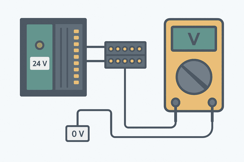
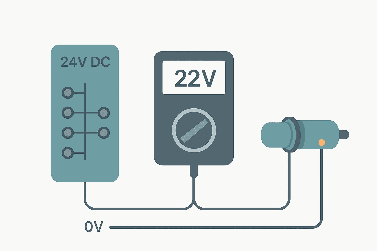
Put your meter leads on the input terminal and the 0 V common terminal on the same module. Do not measure to earth ground. Measure to the module's own input common. You want to see one of two clear states:
- 18 to 30 VDC when the sensor is activated (input should be ON)
- 0 to 5 VDC when the sensor is deactivated (input should be OFF)
- Anything between 5 V and 15 V is unreliable territory. The input may toggle randomly.
If you read 24 V at the terminal but the software bit stays OFF, the module channel itself has failed. If you read 0 V but the sensor LED is on, you have an open circuit somewhere in the wiring between the sensor output and the terminal, or the sensor output type does not match the module input type. The PLC I/O Fault Diagnosis with a Multimeter guide has a worked example of this exact measurement sequence.
Step 3: Isolate the Field Wiring from the Module
Disconnect the sensor cable at the PLC input terminal. Now do one of two things depending on the fault type:
- For a stuck-ON fault: with the wire disconnected, check if the input bit goes OFF. If it does, the fault is in the field cable or sensor (leakage current or a short to 24 V along the cable run). If the bit stays ON with nothing connected, the module channel is internally failed.
- For a stuck-OFF fault: apply 24 VDC directly to the input terminal from a known-good bench supply or from the panel 24 V rail via a test lead. If the bit goes ON cleanly, the module is good and the problem is in the field wiring or sensor.
- For chattering: disconnect the field wire and touch a short test lead from the 24 V rail to the terminal by hand. If the bit is now clean and steady, the chattering is coming from the cable run or the sensor. If it still chatters with a clean bench connection, suspect the module.
Step 4: Check the Sensor Output Type Against the Module
This is the one that catches people out on commissioning more than any other. A PNP sensor sources current to the input terminal. An NPN sensor sinks current from the input terminal. If you wire a PNP sensor to a sinking-type input card, it will not work correctly, and vice versa. The 3-Wire Sensor Wiring: PNP vs NPN to PLC Inputs article explains the wiring in detail, and the Sinking vs Sourcing PLC I/O: Wiring It Right article covers the module side.
On a job commissioning a palletising cell a few years ago, we had three proximity sensors wired correctly according to the drawing, but every one of them stuck ON. The sensors were NPN (sinking output) and the input module was a sourcing card. The drawing was wrong. Every sensor was replaced before someone finally checked the module datasheet. Do not make that mistake.
Step 5: Check Input Filter Settings
Every PLC input module has a configurable filter time, sometimes called input delay or debounce time. Most modules ship with a default of 1 to 8 ms. That is fine for pushbuttons and limit switches. But if you have a high-speed proximity sensor triggering on small parts at 200 parts per minute, a 4 ms filter might be causing you to miss pulses entirely.
On the other hand, if you have chattering from electrical noise, increasing the filter to 12 or 20 ms often clears it immediately without any hardware changes. In TIA Portal, filter time is set per channel in the device configuration under Input delay. In Studio 5000, it is under the module properties as Input Filter. In GX Works3, the parameter is the input response time set in the CPU or module parameters.
Step 6: Inspect the Physical Wiring and Terminal Connections
Loose terminals cause more intermittent input faults than failed modules and failed sensors combined. Loosen and re-torque every terminal in the circuit. Check for strand whiskers from a stranded wire that are touching an adjacent terminal. Check ferrule crimps: a poorly crimped ferrule can grip the insulation instead of the conductor, leaving almost no metal in the terminal.
Also check the cable route in the panel. Are the signal cables bundled with 230 VAC or motor drive cables? Inductive and capacitive coupling from motor power cables is a very common cause of digital input noise. The fix is physical separation. Run signal cables on a separate duct, ideally 100 mm or more away from power cables. The Control Panel Wire Routing and Segregation article has the specific separation rules.
Step 7: Check the 0 V Common and Power Supply
This one is often forgotten. Every digital input module has a 0 V common terminal that must be wired back to the negative rail of the 24 VDC supply. If that common wire is broken or missing, none of the inputs on that module will work. The symptoms look exactly like a blown fuse or a dead module.
Measure between the 0 V common terminal on the input module and the 0 V rail on the power supply. You should read zero volts, or at most a few millivolts. If you read anything significant, you have a broken or high-resistance common connection. Also check the supply voltage itself: a sagging 24 VDC supply below 18 V will cause all inputs on the module to behave erratically. The PLC Power Supply Faults: How to Diagnose Them article covers supply issues in full.
When the Module Itself Has Failed
A genuine module channel failure is less common than wiring faults, but it does happen, especially on older hardware or after a wiring fault injects an overvoltage. Signs that the module itself has failed:
- The input bit is stuck ON or OFF even with the terminal completely disconnected
- Multiple channels on the same module fail at the same time
- The module reports a hardware fault or diagnostic error in the programming software
- The module's status LED shows a fault colour (red or amber) rather than green
Before you condemn a module, check the module's diagnostic registers in software. In TIA Portal, the device diagnostics page will show a channel-level fault. In Studio 5000, the module fault log in the controller organizer tells you exactly which channel reported a fault and what type. This saves you swapping a good module. Checking module-level diagnostics is also covered in the Types of PLC Modules: I/O, Comms and More overview.
Intermittent Faults: The Hardest Case
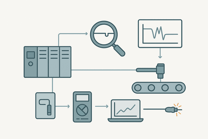
An input that fails only occasionally under vibration, temperature or load is the hardest fault to catch. The best tool here is data logging. Most PLCs let you log the state of a tag over time with a timestamp. Set up a simple trend or data log on the input bit and any related tags (machine state, cycle count) and let it run for a full shift. When the fault reappears in the log, you have the exact time and context.
If your SCADA or historian is connected, use it. The SCADA Historian: How Process Data Gets Logged article explains how to set up input-level logging. For a deeper look at the intermittent sensor problem specifically, Intermittent Sensor Faults: How to Find Them is worth reading alongside this post.
A Practical Diagnosis Checklist
- Go online and watch the raw input bit. Note whether it matches the sensor LED.
- Measure the terminal voltage (input to module 0 V common) with the sensor activated and deactivated.
- Disconnect the field cable and test the module channel directly with a bench supply.
- Confirm the sensor output type (PNP or NPN) matches the module input type.
- Check and adjust the input filter time in module configuration.
- Re-torque all terminals in the circuit. Inspect ferrule crimps and check for strand whiskers.
- Check cable routing for proximity to power or drive cables.
- Measure the 0 V common wire continuity and the supply voltage at the module.
- Check module diagnostic registers for channel-level fault codes.
- If intermittent: set up data logging on the input bit and run for a full shift.
What to Read Next
If you have confirmed the input module is fine and the fault is on the output side, PLC Output Faults: How to Diagnose Them Fast follows the same structured approach for output circuits. For a complete hands-on test procedure with a multimeter, How to Test a PLC Input: Step-by-Step Guide walks through the physical measurements in detail. And if your faults only appear under machine vibration or thermal cycling, the methods in Intermittent Sensor Faults: How to Find Them will give you the data-capture strategy you need.
Frequently asked questions
Why does my PLC input show ON in software but the sensor LED is off?
What causes a PLC digital input to chatter or flicker rapidly?
How do I know if the fault is in the sensor or the PLC input module?
What voltage should I see at a 24 VDC PLC digital input terminal when it is ON?
Can a PLC input be damaged by overvoltage?
What is input filter time and when should I change it?
My PLC input works fine on the bench but faults in the machine. What should I check?
How do I diagnose a PLC input that is stuck OFF even though the sensor is clearly activated?
Do I need to power-cycle the PLC to clear an input fault?
Learn this by building it
There is a PLC in this site. It runs a real scan engine, checks your logic against the same tests a working machine would fail, and needs no download and no account.
Open the exercisesFree, no signup, runs in your browser. See all 16 exercises.
Was this helpful?