PLC Fault Finding: A Systematic 6-Step Method
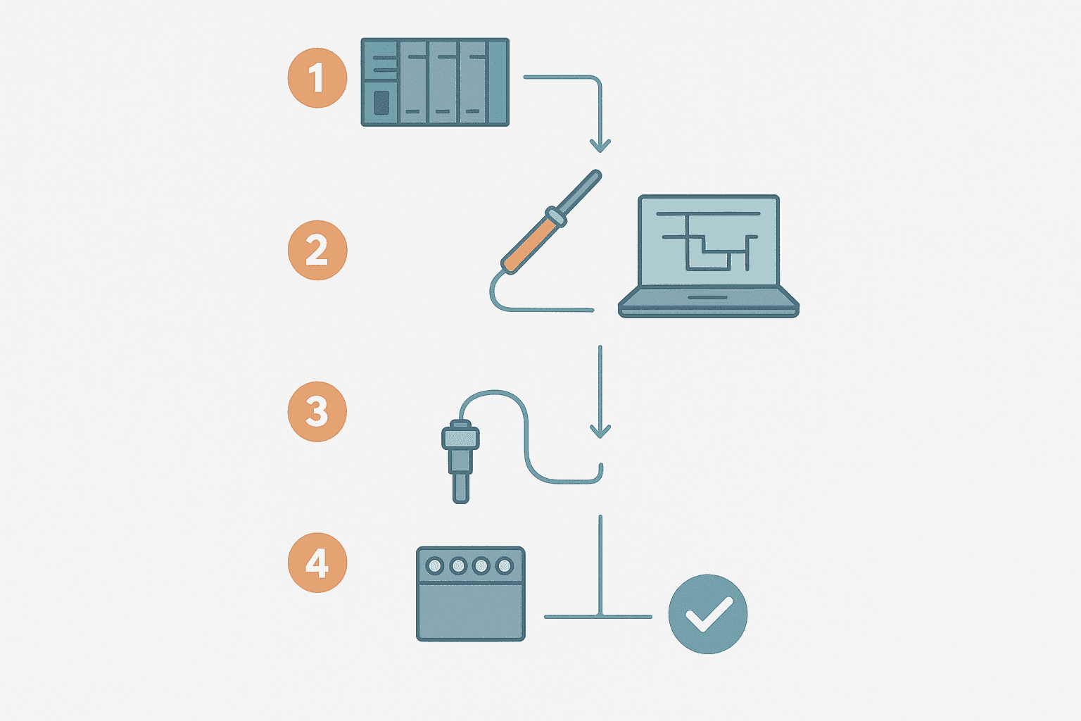
The machine is down. The PLC fault LED is on. Your phone is ringing. The worst thing you can do right now is start swapping hardware at random. PLC fault finding is a skill, not a lottery, and a repeatable six-step method will get you to the root cause faster than intuition alone every single time.
What Is PLC Fault Finding?
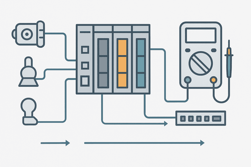
PLC fault finding is the systematic process of identifying and correcting the root cause of a malfunction in a PLC-controlled system. It covers the full signal chain from the field device through the wiring and I/O module to the CPU program, using diagnostic tools, online monitoring and physical measurements to isolate the fault layer before any part is replaced or any code is changed.
Why Random Swapping Wastes Hours
I once watched a technician spend four hours on a Siemens S7-300 system swapping I/O cards because the conveyor would not start. The real fault was a 24 V common wire that had worked loose from a terminal block three metres away. Ten minutes with a multimeter would have found it. The hardware was fine the entire time.
Random swapping costs money in unnecessary spares, risks introducing new faults (ESD damage, wrong firmware), and leaves the root cause unfound. A structured method eliminates that waste.
The 6-Step PLC Fault Finding Method
Step 1: Gather the Clues Before You Touch Anything
Talk to the operator first. What was the machine doing when it stopped? Was there a bang, a smell, a flicker? What changed recently (new product, a maintenance visit, a power event)? Then read every LED on the front of the PLC rack: RUN, ERR, I/O fault, COMM fault. These indicators are free information.
Open the diagnostic buffer in your programming software. In TIA Portal it is under Online and Diagnostics. In Studio 5000 it is the Controller Properties fault tab. You are looking for the first event, not the last, because subsequent faults are often cascade effects of the original problem. A timestamp matters: a CPU fault logged at 03:14 AM on a Monday might point to a shift changeover or an overnight power blip.
Step 2: Identify the Fault Layer
Every PLC fault lives in one of five layers. Identifying the layer first cuts your search space dramatically.
| Layer | Typical Symptoms | First Check |
|---|---|---|
| Power supply | All outputs OFF, CPU not starting, voltage LED off | Measure 24 VDC at supply output terminals |
| CPU / program | Fault LED solid, CPU in STOP, error code in diagnostic buffer | Read fault code, check program for unhandled conditions |
| I/O module | Single channel or card offline, module fault LED | Online I/O status table, card slot indicators |
| Wiring / terminals | Input reads wrong state, output does not activate field device | Multimeter at PLC terminal and at device |
| Field device | Sensor not switching, actuator not moving, drive faulted | Check device LED, measure supply to device, check signal output |
Power supply faults are covered in depth in PLC Power Supply Faults: How to Diagnose Them. CPU-level faults, including error codes, are covered in PLC CPU Faults: How to Diagnose Them Step by Step. For vendor-specific error codes, see Siemens PLC Error Codes, Omron PLC Error Codes or Mitsubishi PLC Error Codes.
Step 3: Use Online Monitoring to See the Logic State
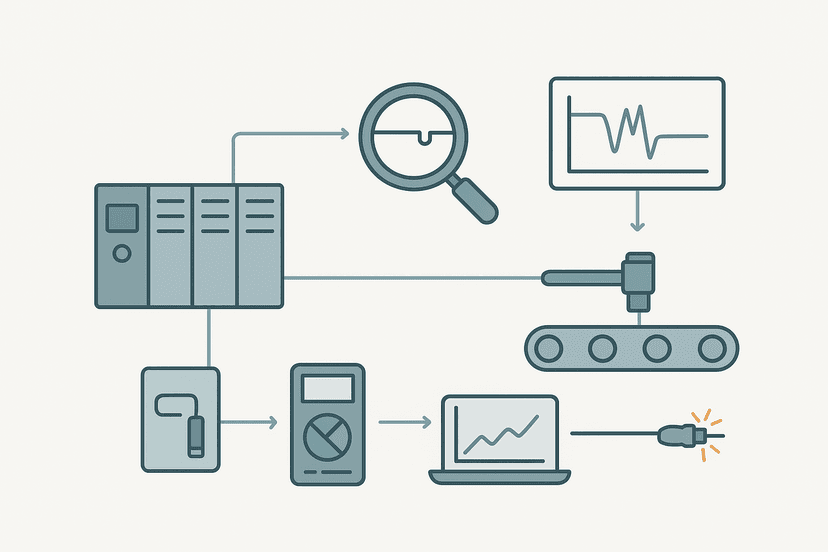
Connect your laptop and go online. Navigate to the rung or function block that controls the faulted output. Watch the live contact states. A contact that should be true but is shown false is your next lead. Follow it back to its source tag, then to the physical I/O address.
This is the single fastest fault-finding technique available and it costs nothing. PLC Troubleshooting with Online Monitoring covers the full workflow including cross-referencing tags. For intermittent faults that disappear when you connect, data logging and trend tools in the SCADA historian are your next option, see SCADA Historian: How Process Data Gets Logged.
Step 4: Measure at the Terminals
Online monitoring tells you what the PLC thinks. A multimeter tells you what is actually there. These two pieces of information together pinpoint the fault layer precisely.
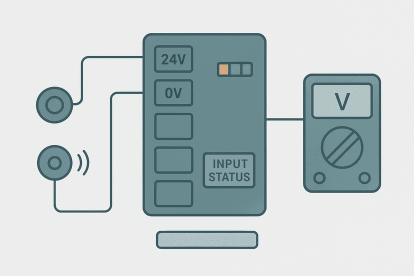
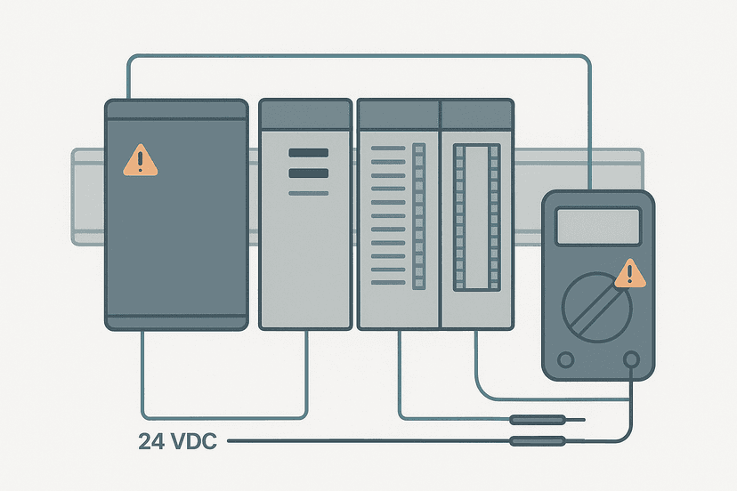
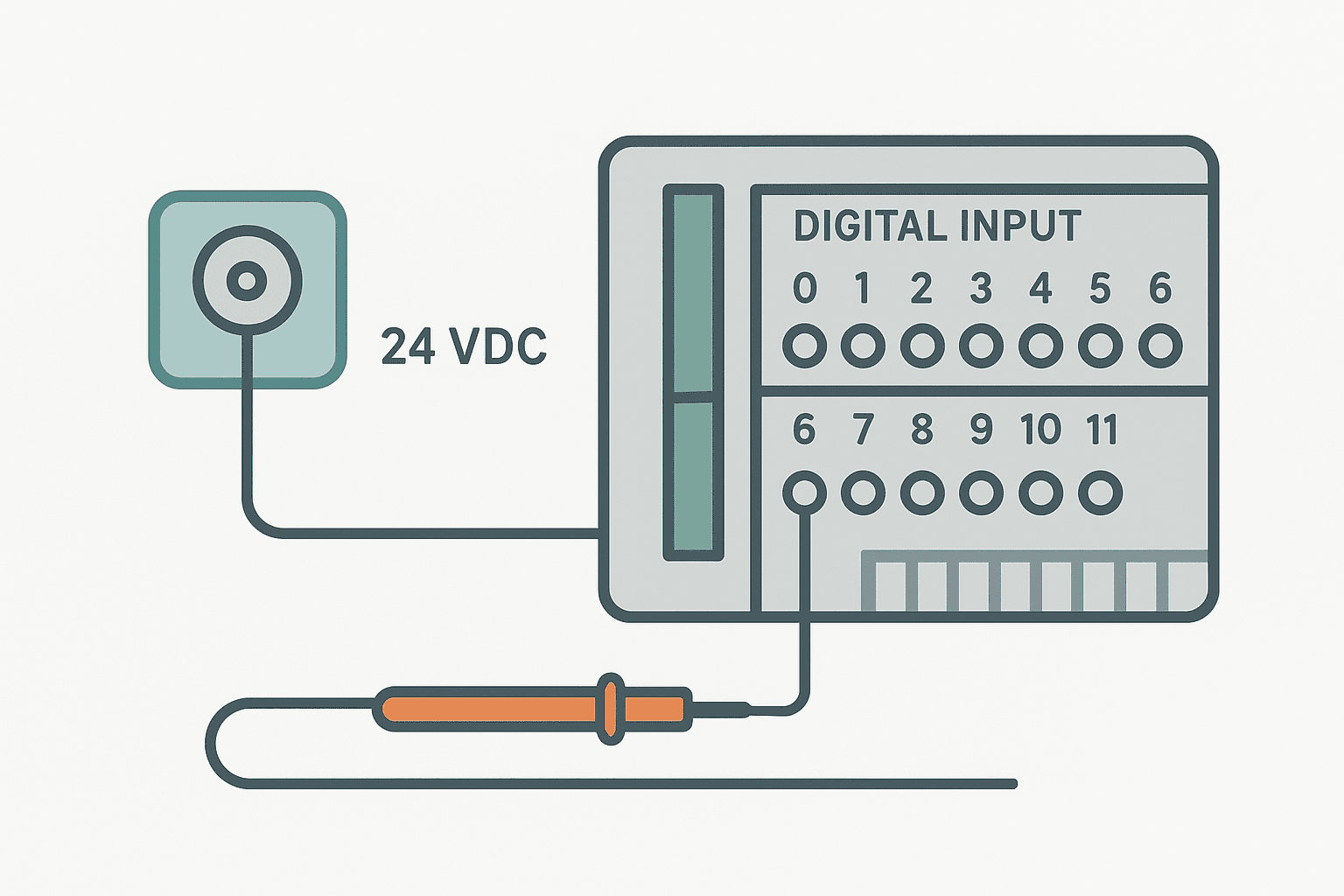
For a digital input that reads OFF when it should be ON: measure voltage between the input terminal and the input common. If you see 24 VDC and the PLC still reads OFF, the input card or its circuitry is suspect. If you see 0 V, the fault is upstream: the sensor, the wiring, or the 24 V supply to that sensor. PLC I/O Fault Diagnosis with a Multimeter has the exact measurement procedure. For digital input-specific faults, see PLC Digital Input Faults: How to Diagnose Them.
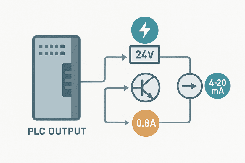
For outputs: measure at the output terminal with the output commanded ON by the program. Voltage present but field device not responding means the fault is downstream of the PLC terminal: wiring, fuse or the device itself. No voltage with the output commanded means a failed output card, a blown output fuse on the card, or a missing common. The full output procedure is in PLC Output Faults: How to Diagnose Them Fast.
Step 5: Isolate and Confirm with a Force (Carefully)
Once you suspect a specific hardware item, force the relevant I/O point in software to confirm the logic path works correctly without the suspect device. If forcing the input ON makes the output activate and the machine logic progresses normally, you have confirmed the fault is in the field device or its wiring, not in the program.
Forces are powerful. Follow your site's isolation procedure before applying any force to an output. In Allen-Bradley Studio 5000, forced values are shown with an F badge and persist through power cycles until explicitly removed. In TIA Portal, forcing is done via the watch table with the force column. Always remove forces before returning the machine to production.
For sensor-related faults, especially ones that appear and disappear, Intermittent Sensor Faults: How to Find Them is worth reading before you reach for the force function. Many intermittent faults are caused by poor wiring practices covered in 3-Wire Sensor Wiring: PNP vs NPN to PLC Inputs or incorrect sinking and sourcing wiring, see Sinking vs Sourcing PLC I/O: Wiring It Right.
Step 6: Fix, Verify and Document
Fix only what the evidence points to. Re-terminate that loose wire, replace that failed proximity sensor, re-seat that I/O card. Then verify: remove all forces, put the PLC back into RUN, cycle the machine through its normal sequence, and confirm the fault does not return.
Document what you found. A one-paragraph entry in the maintenance log, recording the fault symptom, the root cause and what was done to fix it, is worth more than a shelf of manuals. The next engineer who sees the same symptom will solve it in five minutes instead of four hours.
Communication and Network Faults: A Special Case
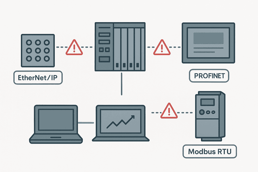
Communication faults follow the same six steps but add a network layer between the CPU and the I/O. A PROFINET device going offline, an EtherNet/IP adapter dropping out, or a Modbus RTU timeout all show up as I/O module faults in the diagnostic buffer, but the physical fault is in the network cable, the switch port, the IP address configuration, or the device firmware.
Start by checking link LEDs on the switch and device. A solid green link LED eliminates the physical layer immediately. If the link is up but comms are dropping, check for duplicate IP addresses or subnet mismatches. The full network fault workflow is in PLC Communication Faults: How to Diagnose Them. For PROFINET specifically, PROFINET Communication Loss: How to Diagnose It covers the step-by-step.
Ground Faults and Wiring Problems That Mimic PLC Faults
One of the sneakiest fault categories is a ground fault that causes false triggering of inputs or random output chatter. The PLC logs no error code because electrically everything looks normal from the CPU's perspective. You see random input bits toggling with no field activity. How to Find a Ground Fault in a Control Panel walks through the isolation technique. Poor cable shield grounding in analog loops also generates what looks like a sensor fault but is actually electrical noise: Shielding Analog Signal Cables in PLC Panels has the fix.
A Quick Reference: Fault Symptoms and Where to Start
| Symptom | Most Likely Layer | First Action |
|---|---|---|
| CPU in STOP, fault LED solid red | CPU / program | Read diagnostic buffer for exact error code |
| One input always OFF | Wiring or field device | Measure 24 V at input terminal with multimeter |
| Output card channel not switching | I/O card or output fuse | Check card fuse, measure at terminal with output forced ON |
| Comms module offline | Network or device config | Check link LED, ping device, verify IP subnet |
| Random input toggling with no activity | Grounding or noise | Check cable shield connections and panel grounding |
| Intermittent fault, clears itself | Loose terminal or thermal | Log with SCADA trend, check terminations at temperature |
Keep Learning
The six-step method gives you the framework. The detail is in the individual fault categories. Work through PLC Troubleshooting with Online Monitoring to sharpen your software-side skills, then PLC I/O Fault Diagnosis with a Multimeter for the physical measurement techniques. If you are preparing for a technical interview, PLC Troubleshooting Interview Questions: Real Answers covers the questions interviewers actually ask about fault finding.
Frequently asked questions
What is PLC fault finding?
What are the most common causes of a PLC fault?
How do I find which PLC input is faulted?
Can I troubleshoot a PLC fault without the original program?
What does a flashing fault LED on a PLC mean?
How long should PLC fault finding take?
What tools do I need for PLC fault finding?
Is it safe to force a PLC output during fault finding?
What is the difference between a fault and an alarm on a PLC?
How do I reset a PLC fault without losing production data?
Learn this by building it
There is a PLC in this site. It runs a real scan engine, checks your logic against the same tests a working machine would fail, and needs no download and no account.
Open the exercisesFree, no signup, runs in your browser. See all 16 exercises.
Was this helpful?