PLC Analog Output Faults: How to Diagnose Them
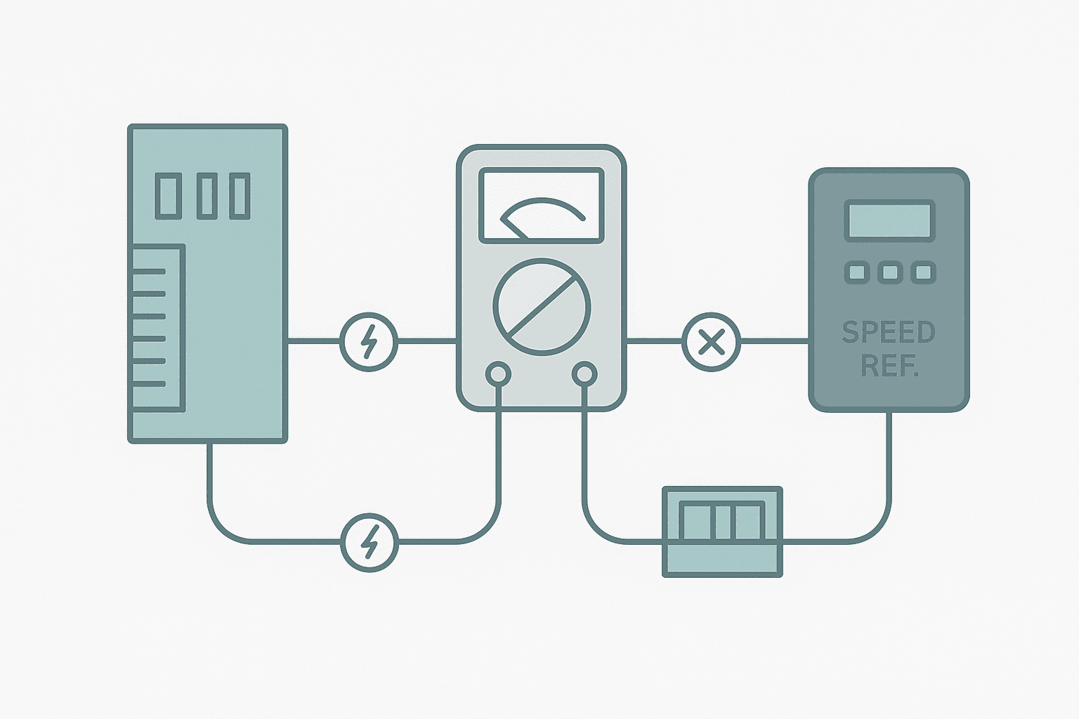
You have a VFD that will not ramp up, a control valve that stays shut, or a speed reference that never changes no matter what the operator does. You go online, check the PLC program, and the tag driving the analog output looks perfectly correct. So where is the fault? Analog output problems are frustrating because the failure can live anywhere from the PLC tag to the module channel to the field wiring to the receiving device, and every layer looks innocent until you test it properly.
What Is a PLC Analog Output Fault?
A PLC analog output fault is any condition where the module's physical output signal, whether 4-20 mA or 0-10 V, does not match the value the PLC program has commanded. The fault can be electrical (open loop, short, wrong supply voltage), configuration-related (wrong mode, scaling error, channel disabled), or in the receiving device (wrong input mode, incorrect parameter, impedance mismatch). The PLC itself often has no idea a fault exists because analog outputs are not inherently closed-loop: the module sends a signal but cannot confirm the field device received it correctly.
Start With Online Monitoring, Not the Screwdriver
Before you grab a multimeter, spend two minutes in the programming software. PLC Troubleshooting with Online Monitoring is the fastest first step. Look at the raw integer tag that feeds the analog output channel. On most platforms the output word holds a value from 0 to 27648 (Siemens), 0 to 32767 (Rockwell) or 0 to 4095 depending on the module resolution. Confirm that value is moving when you expect it to. If the raw count is correct but the output is wrong, the fault is in the module or wiring. If the raw count is stuck or zero, the fault is upstream in the PLC program or scaling.
Check Module Configuration Before Anything Else
Half the analog output faults I have seen on commissioning jobs were configuration problems, not hardware faults. The module was wired for current but the software had the channel set to voltage mode. Or someone had disabled the channel during a previous fault investigation and forgotten to re-enable it. On some Rockwell 1756-OF8 modules the channel enable bit lives in the configuration tag tree, not in the main I/O data, so it is easy to miss.
Check these configuration items on every platform before you touch a wire: output type (current vs voltage), output range (4-20 mA vs 0-20 mA vs 0-10 V), channel enable/disable state, fault action (hold last value, go to zero, go to a defined value), and the raw count range the module expects. The 4-20 mA Scaling Formula post covers the math in detail if your scaling looks suspicious.
Systematic Wiring Fault Isolation: The Split-and-Measure Method
Once you have confirmed the raw count is correct and the channel is configured properly, the fault is in the physical loop. The split-and-measure method works on any analog output regardless of PLC brand.
- Command the PLC output to a known mid-scale value, say 12 mA (50%) or 5 V (50% on a 0-10 V range).
- Disconnect the field device (VFD, valve positioner, I/P transducer) from its terminal block. Measure the open-circuit voltage at the module terminals. A 4-20 mA current source should show near the compliance voltage (typically 12-24 V) when open-circuit. A 0-10 V source should show the commanded voltage.
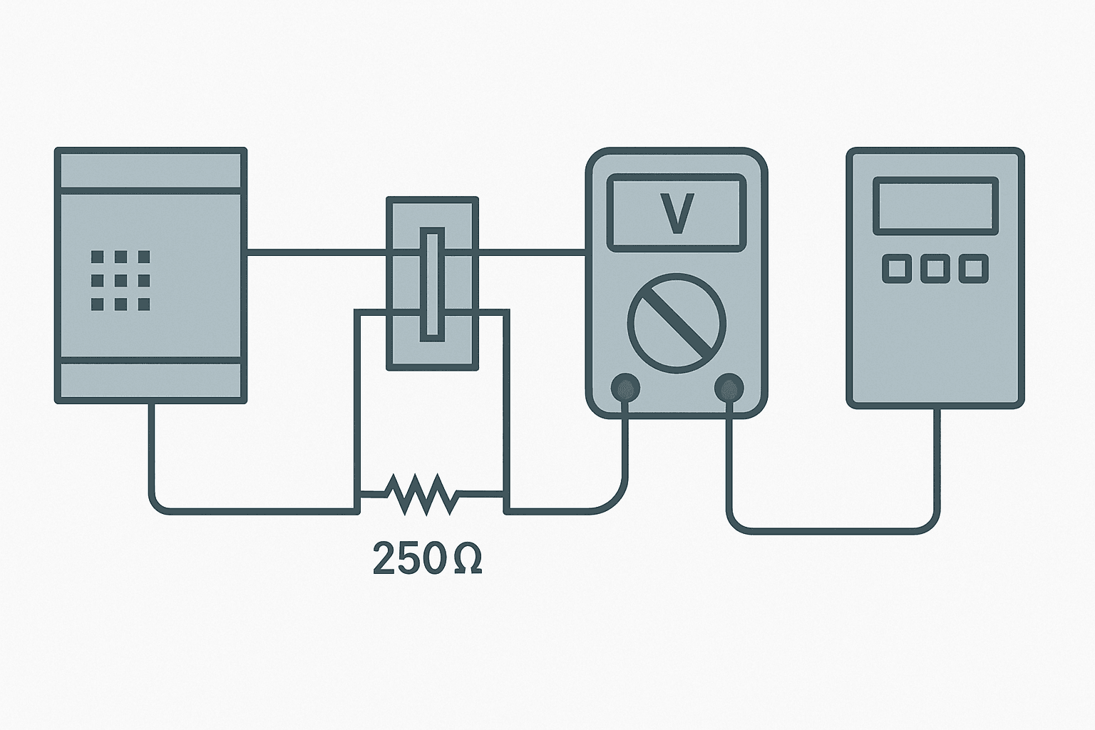
- Now connect a precision 250-ohm resistor across the terminals (for 4-20 mA loops). Measure the voltage across it. At 12 mA you should read 3.0 V. This confirms the module is sourcing correctly.
- Re-connect the field device terminals one at a time. If the reading drops or disappears when you reconnect, the field device input is loading the loop below the module's compliance limit, or is shorted internally.
- If the reading was wrong even with the 250-ohm test load, the fault is in the module or the cable between the module and the terminal block. Check for continuity, check for a short to another conductor, and check the module diagnostic LED.
Loop Impedance: The Fault Nobody Talks About
A PLC analog output module is a current source with a finite compliance voltage. That means there is a maximum total loop resistance it can drive before the current falls short of the commanded value. A typical PLC AO module specifies a maximum load of 500 ohms. Add up: the field device input impedance (often 250 ohms for a VFD or positioner), the cable resistance (0.017 ohms per metre for 1.5 mm2 copper, so a 100-metre run adds about 3.4 ohms), and any signal isolators or safety barriers in the loop. A galvanic isolator can add 50-200 ohms on its own.
When the total impedance creeps over the module's rating, the output current saturates at something below 20 mA. The PLC sees the raw count as correct but the field device receives less than the commanded signal. The symptom is that 0-12 mA works fine but 12-20 mA is compressed. If you suspect this, use the analog scaling calculator to verify your raw counts are in order, then measure the actual mA in the loop at various setpoints.
Common PLC Analog Output Fault Causes
| Symptom | Most Likely Cause | First Check |
|---|---|---|
| Output reads 0 mA / 0 V regardless of command | Channel fault, open loop, or channel disabled | Module diagnostic LED and channel enable bit |
| Output stuck at 4 mA (current mode) | Module defaulting to fail-safe minimum due to fault | Check module fault buffer and loop wiring |
| Output stuck at 20 mA | Raw output tag at max or unsigned int overflow | Read raw count in online monitoring |
| Output correct at module, wrong at device | Loop impedance too high, or device in wrong input mode | Measure mA at device terminals, check device parameter |
| Output noisy or hunting | Ground loop or missing cable shield connection | Check shield grounding; see below |
Ground Loops and Noise on Analog Output Loops
If the output signal is correct but the VFD or valve is hunting or showing erratic behaviour, a ground loop is the usual suspect. This happens when the signal cable shield is connected at both ends and a potential difference exists between the panel earth and the field device chassis. The result is a circulating current that adds noise to the 4-20 mA signal. The fix is to connect the shield at one end only, typically the panel end, and leave the field end floating. Cable Shield Grounding: One End or Both? and Shielding Analog Signal Cables in PLC Panels go into the full reasoning.
A related issue is routing analog signal cables alongside power cables. Even a short parallel run of 0.5 metres next to a VFD output cable can inject enough noise to cause 1-2 mA of ripple. Control Panel Wire Routing and Segregation covers the segregation distances you should maintain in a panel.
When the Field Device Is the Problem
You have confirmed the module is outputting the right signal. The problem is the VFD, valve positioner, or I/P converter. On a VFD this is almost always a parameter setting. The drive's analog input channel has to be configured to match: current vs voltage, range (0-20 mA vs 4-20 mA vs 0-10 V), and the reference source must be set to the analog input terminal rather than the keypad. VFD Parameters Explained lists the common parameters across major drive brands. A 4-20 mA signal wired to a drive configured for 0-10 V will produce a speed reference of 40-100% rather than 0-100%, which is a classic commissioning gotcha.
For control valves with electro-pneumatic positioners, a common problem is the positioner's zero and span calibration being off. The positioner may be expecting 4 mA for fully closed but its zero pot has drifted. This is a mechanical calibration issue, not a PLC fault, but it presents exactly like one. Confirm the mA signal is correct at the positioner terminals first, then adjust zero and span on the positioner if needed.
Scaling Faults: The Invisible Error
Scaling faults are output faults that nobody calls output faults. The module is working perfectly, but the program is writing the wrong raw count. Typical causes: the engineering-unit-to-raw-count formula has the wrong raw minimum or maximum, someone has changed the output range in module configuration without updating the scaling code, or a REAL-to-INT conversion is truncating instead of rounding. The result is that the output seems to work over part of the range but runs out of travel early or is offset from zero.
The 4-20 mA Scaling in a PLC: ST and Ladder Code post has working code examples for both Structured Text and Ladder. If you need to verify the raw counts interactively, the analog scaling calculator lets you plug in your EU range and raw count range to check the expected output at any setpoint.
Module Diagnostics: Read the Fault Buffer
Every modern analog output module keeps a diagnostic buffer. On Siemens S7-1200 and S7-1500 you can read channel diagnostic bits in TIA Portal's device diagnostics view, and the module will flag open-wire, short-circuit, or configuration errors specifically by channel. On Rockwell ControlLogix the module properties in Studio 5000 show channel faults under the Fault tab in real time. Read those buffers before replacing any hardware. A hardware swap on a module that has a configuration fault just wastes time and money.
If you are on a Siemens platform, Siemens PLC Error Codes: How to Read and Fix Them walks through the diagnostic structure including how I/O module faults surface in the diagnostic buffer. For a broader fault-finding framework that covers this step in context, PLC Fault Finding: A Systematic 6-Step Method is worth reading alongside this post.
A Quick Diagnostic Checklist
- Confirm raw output count in online monitoring matches the expected value for the commanded setpoint.
- Check channel configuration: current vs voltage mode, output range, channel enable.
- Read module diagnostic buffer for channel-specific fault codes.
- Measure loop current at module terminals with a series multimeter (use a precision 250-ohm shunt if needed).
- Measure loop current at field device terminals and compare to module terminal reading.
- Check total loop impedance against module compliance specification.
- Verify field device is configured for the correct input type and range.
- Inspect cable shield connection: one end grounded, other end floating.
- Check cable routing for proximity to power or VFD cables.
- Check for ground loop by temporarily lifting the shield at the field end and observing noise change.
Analog output faults are almost always solvable without replacing hardware. In my experience, roughly 60% are configuration or scaling issues, 25% are wiring faults (open circuit, wrong terminal, missing shield), and only about 15% are actual module hardware failures. Work through the software layers first, then the wiring, and save the module swap for last. For the wiring side of the diagnosis, PLC I/O Fault Diagnosis with a Multimeter covers the measurement techniques in more detail.
What to Read Next
If you want to build a complete fault-finding picture, pair this post with PLC Output Faults: How to Diagnose Them Fast for digital output faults and PLC Digital Input Faults: How to Diagnose Them for the input side. For the full structured approach to any PLC fault, start with PLC Fault Finding: A Systematic 6-Step Method and use this post as the analog output chapter within it.
Frequently asked questions
How do I test a PLC analog output with a multimeter?
Why does my PLC analog output read 0 mA instead of 4 mA at minimum?
What causes a PLC analog output to be stuck at maximum (20 mA)?
Can a short circuit damage a PLC analog output module?
What is the difference between a sourcing and sinking analog output?
Why does my analog output work in the PLC but the VFD ignores it?
How do I force a PLC analog output to a specific value for testing?
What load resistance limits apply to a 4-20 mA analog output?
What does an analog output channel fault LED mean on a PLC module?
Learn this by building it
There is a PLC in this site. It runs a real scan engine, checks your logic against the same tests a working machine would fail, and needs no download and no account.
Open the exercisesFree, no signup, runs in your browser. See all 16 exercises.
Was this helpful?