What Is a PLC Controller and How Does It Work?
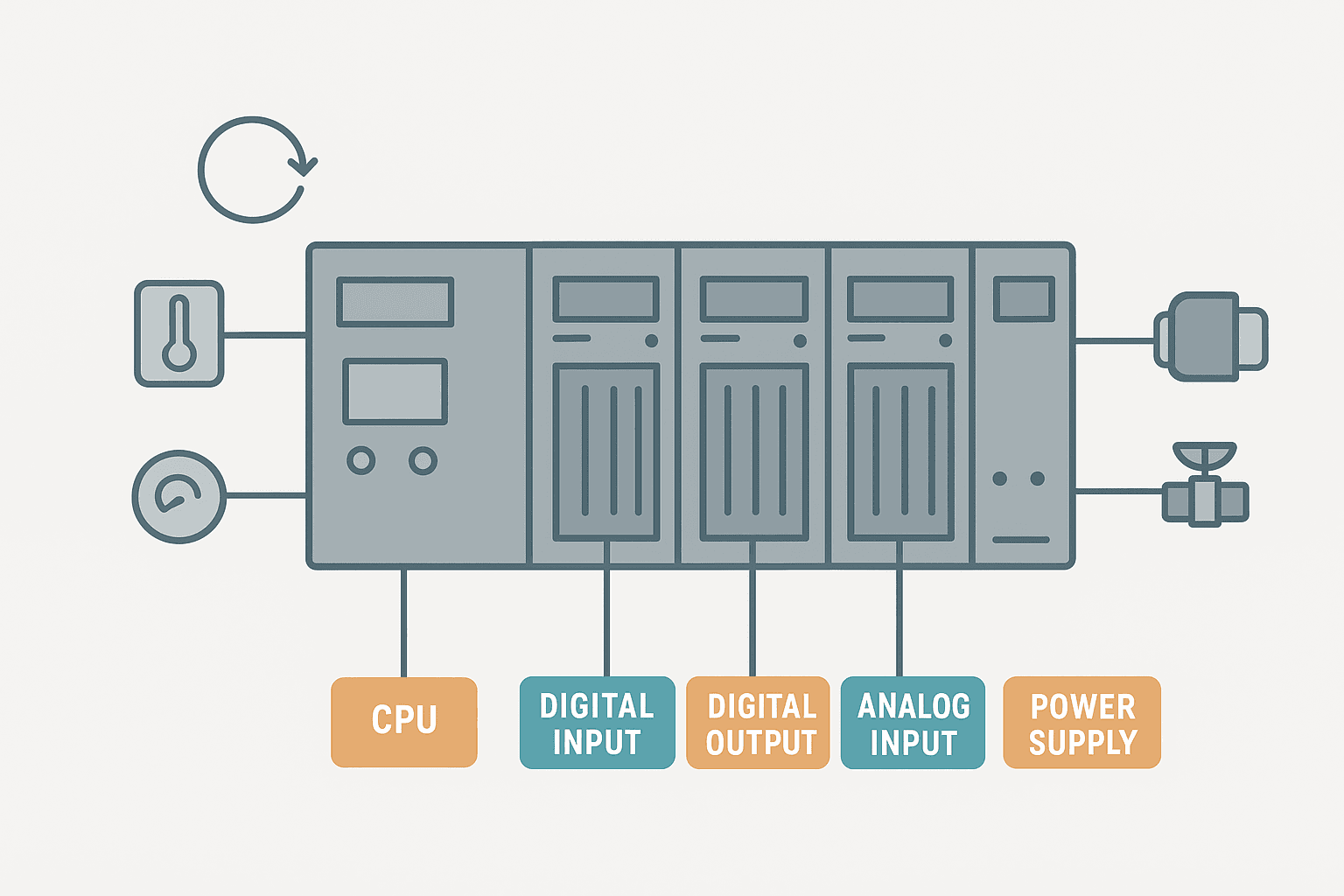
A PLC controller is the brain of almost every automated machine you will encounter in a plant. Conveyor systems, bottle fillers, pump stations, traffic signals, car washes: they all run on a PLC. If you are new to automation or just want a solid mental model of what is actually happening inside that rack, this is the right place to start.
What Is a PLC Controller?
A PLC (Programmable Logic Controller) is a ruggedized industrial computer that reads sensor inputs, executes a stored logic program, and drives outputs such as motors, valves, and indicator lights in a deterministic, repeating cycle. Unlike a general-purpose PC, a PLC is built to survive electrical noise, vibration, and wide temperature swings on the factory floor, and it responds to real-world signals in a predictable 1 to 20 ms scan time.
Why PLCs Replaced Relay Panels
Before PLCs, logic was built from physical relays wired together in panels. Changing a sequence meant rewiring. A relay panel for a 50-step machine could fill an entire wall cabinet and take weeks to modify. When General Motors and Bedford Associates developed the first programmable controller in 1968, the goal was simple: replace the wiring with software.
Today, a single CPU module handles what used to take hundreds of relays. Modifying logic takes minutes in software. That is the real value: flexibility without rewiring.
PLC Hardware: The Main Components
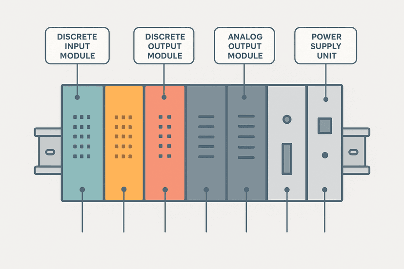
Every PLC, from a tiny Mitsubishi FX5U to a full Rockwell ControlLogix rack, shares the same fundamental hardware blocks. Understanding each one makes wiring, troubleshooting, and programming much easier.
Power Supply
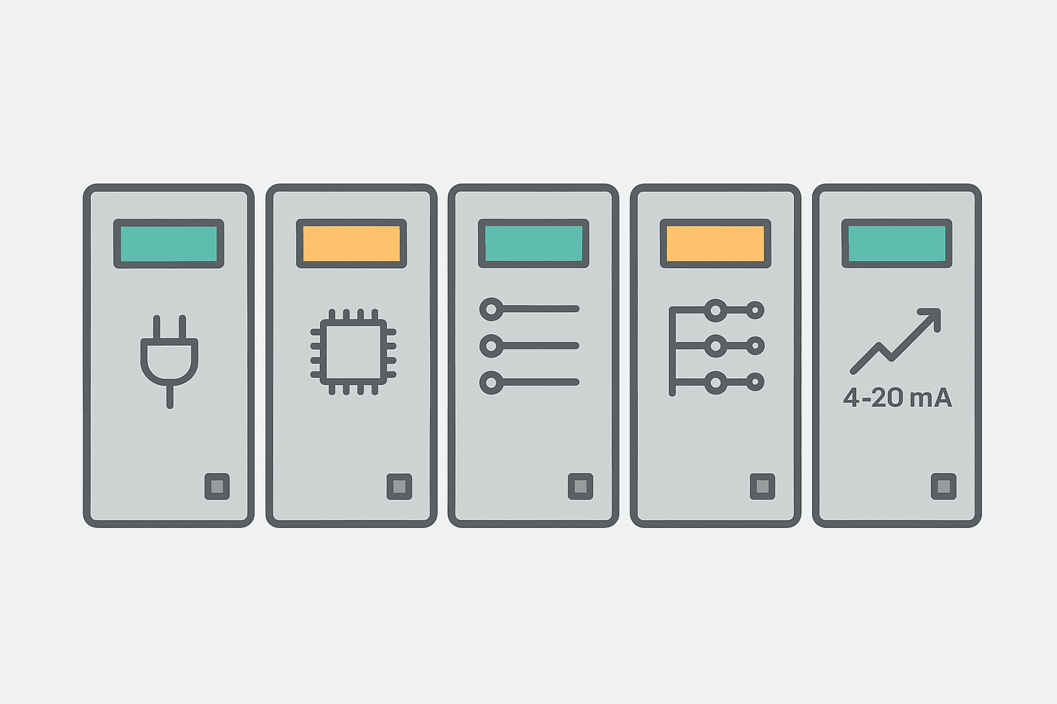
The power supply converts incoming AC (typically 120 V or 240 V) or DC voltage into the 5 VDC and 24 VDC rails the backplane and modules need. Sizing it correctly matters: undersized supplies cause brownouts that reset the CPU mid-scan. The 24 VDC power supply sizing guide covers that calculation in detail.
CPU Module
The CPU is the processor. It holds the user program in non-volatile memory (so it survives a power loss), executes the scan cycle, manages communications ports, and logs diagnostics. Most modern CPUs also have a built-in Ethernet port for programming and HMI connectivity.
Digital Input Modules
Digital inputs accept ON/OFF signals from devices like pushbuttons, limit switches, proximity sensors, and float switches. Each channel converts the field voltage (typically 24 VDC) into a binary 1 or 0 in the input image table. Whether you wire NPN or PNP sensors depends on whether the module is sinking or sourcing, which is a common source of confusion for beginners. The sinking vs sourcing I/O guide explains the difference clearly, and 3-wire sensor wiring shows exactly how to connect PNP and NPN sensors.
Digital Output Modules
Digital outputs switch field devices ON or OFF. Output modules come in three types: relay, transistor (solid-state), and triac. Relay outputs handle higher voltages and mixed AC/DC loads but wear out over time. Transistor outputs switch faster (useful for high-speed pulsing) but are DC-only. If you are not sure which to use, the relay vs transistor output comparison in the modules guide covers the tradeoffs.
Analog Modules
Analog modules read or write continuous signals: 4-20 mA current loops, 0-10 V voltage signals, and thermocouple or RTD temperature inputs. A 4-20 mA signal from a pressure transmitter comes into an analog input module and gets converted to a raw integer count (typically 0-27648 on a Siemens S7, or 0-32767 on a Rockwell module) that your program then scales into engineering units. The PLC analog input wiring guide and the 4-20 mA scaling formula cover both ends of that process.
The PLC Scan Cycle: What Happens Every Millisecond
This is the part most beginners skip, and it is the part that causes the most confusion later. A PLC does not monitor inputs continuously the way a microcontroller in an interrupt-driven loop might. It runs a fixed, sequential scan.
- Read inputs: The CPU copies the current state of every physical input into the Process Image Input (PII) table in memory. This snapshot is what the program sees for the entire scan.
- Execute program: The CPU works through the user program from the first rung (or instruction) to the last, using the input image it just captured. Results are written to the Process Image Output (PIO) table, not directly to the field terminals yet.
- Write outputs: The CPU copies the PIO table to the physical output terminals, updating every output at once.
- Housekeeping: Communications with HMIs, remote I/O, and programming tools are serviced. Diagnostics are updated. Then the cycle starts again.
A typical scan takes 1 to 10 ms on a modern CPU with a modest program. A bloated program with thousands of rungs, large data blocks, and heavy communications overhead can push that to 50 ms or more, which can cause real problems with fast-moving machinery. PLC scan cycle problems are worth reading once you are comfortable with the basics.
PLC Memory: Where Data Lives
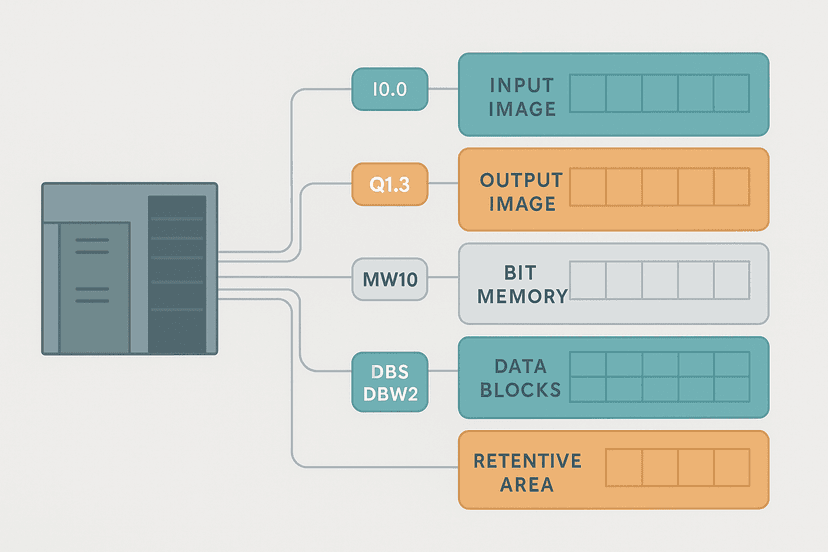
A PLC uses several distinct memory areas, and understanding them saves you a lot of debugging time. The program memory holds your logic. The data memory holds tag values, timer accumulators, counter values, and recipe parameters. Most platforms split this further into retentive memory (values survive a power cycle) and non-retentive memory (values reset to zero on power-up). PLC memory and addressing goes deep on this if you need to understand register maps and indirect addressing.
| Memory Area | Contents | Retentive? |
|---|---|---|
| Program memory | User ladder/ST/FBD logic | Yes (flash) |
| Input image table | Snapshot of physical input states | No |
| Output image table | Pending output states before write | No |
| Data memory / tags | Timers, counters, variables, setpoints | Configurable |
| Diagnostic buffer | Error codes, fault history | Yes (battery or flash) |
PLC Programming Languages
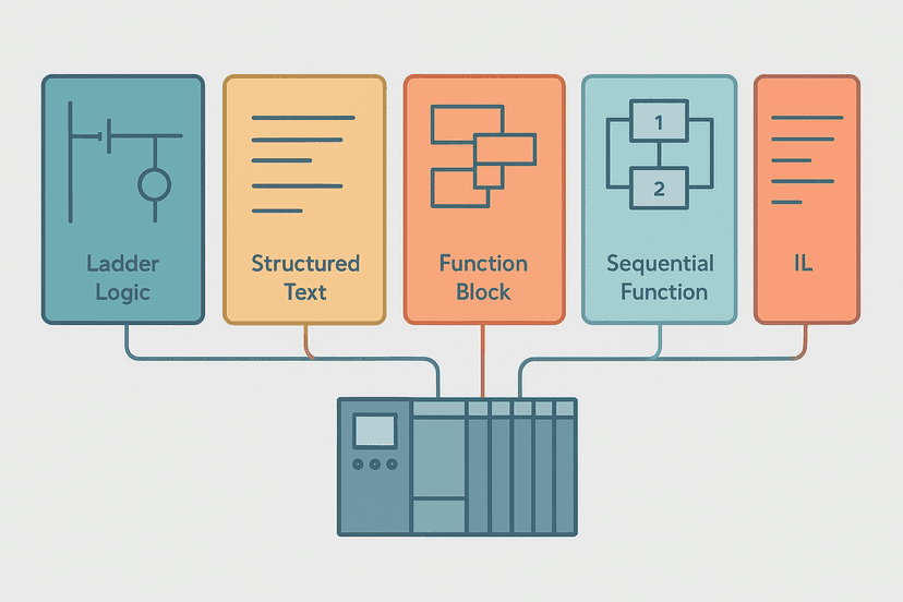
IEC 61131-3 defines five languages. Ladder Diagram (LD) is the most common in North America and Australia because it looks like a relay schematic, making it readable by electricians who may not be software engineers. Structured Text (ST) is a Pascal-like language better suited for math-heavy logic and data manipulation. Function Block Diagram (FBD) is popular in process industries. Sequential Function Chart (SFC) is excellent for step-based sequences like filling machines. The 5 types of PLC programming languages post covers all five with examples.
A Simple Ladder Logic Example
To make this concrete, here is a three-rung ladder program for a basic temperature-controlled heater with a fault latch. The heater runs when the system is enabled and the temperature is below setpoint. If the high-temperature safety switch trips, a fault is latched and the operator must acknowledge it before the heater can run again. This is the pattern you will see repeated across hundreds of real machines.
Temperature Heater Control with High-Temp Fault Latch (Studio 5000). Ladder logic (3 rungs): Rung 0: examine if Sys_Enabled is on (XIC), then examine if Temp_AtSetpoint is off (XIO), then examine if HiTemp_FaultLatch is off (XIO), then energize output Heater_Out (OTE). Rung 1: examine if HiTemp_SafetySwitch is on (XIC), then examine if HiTemp_OS is on (XIC), then latch output HiTemp_FaultLatch (OTL). Rung 2: examine if HiTemp_FaultLatch is on (XIC), then examine if HMI_FaultAck is on (XIC), then examine if HiTemp_SafetySwitch is off (XIO), then unlatch output HiTemp_FaultLatch (OTU). Rung 1: Heater runs when system is enabled, temperature is below setpoint (XIO = Temp_AtSetpoint is OFF), and no fault is latched. Rung 2: Rising-edge one-shot on the high-temperature safety switch sets the fault latch. Rung 3: Operator acknowledge on the HMI clears the latch only after the safety switch has de-activated, preventing a nuisance restart.
The diagram above evaluates one scan. Run these exact rungs on a real scan cycle to watch the latching and the timers behave.
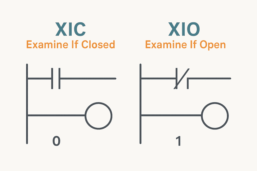
Run this in the simulatorNotice the XIO (Examine If Open) contact on Temp_AtSetpoint in Rung 1. The heater is commanded ON when that tag is FALSE, meaning temperature has not yet reached setpoint. This is a normally-closed contact in ladder logic terms. If you are not clear on XIC vs XIO, the XIC vs XIO contacts explained post and the NO vs NC contacts breakdown are worth reading next.
Where PLCs Fit in the Bigger Automation Picture
A PLC rarely works alone. On most plants, the PLC sits at the control layer: it reads sensors, runs machines, and communicates status up to an HMI or SCADA system. The HMI is the operator interface; the SCADA system collects data from many PLCs across a facility. Understanding how SCADA and PLC work together gives you the full picture of where each technology lives.
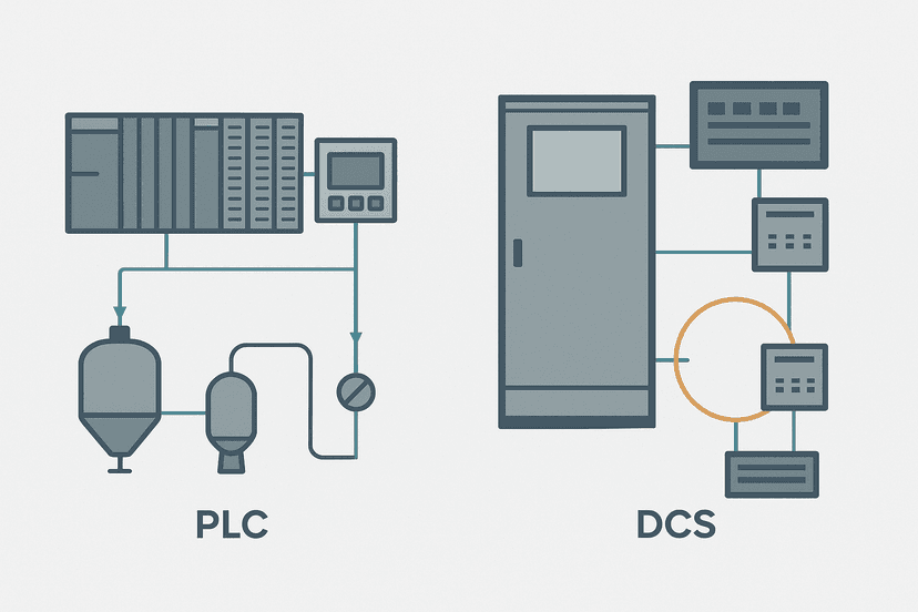
For larger, more continuous processes (refineries, chemical plants), a DCS (Distributed Control System) might replace the PLC. The PLC vs DCS comparison explains when each makes more sense, and if you want to go deeper on the options, PLC vs PAC vs DCS covers all three.
Common PLC Platforms You Will Encounter
No single vendor dominates everywhere. In North America, Rockwell Automation (Allen-Bradley) ControlLogix and CompactLogix are the most common. Siemens S7-1200 and S7-1500 dominate Europe and much of Asia. Mitsubishi FX and iQ-R series are strong in Japan and Southeast Asia. Omron, Keyence, Beckhoff, and Phoenix Contact each have strong niches. If you are starting out on Siemens, the S7-1200 first program guide is a practical hands-on starting point. The S7-1200 vs S7-1500 comparison helps you understand the range within just one vendor family.
Getting Hands-On: Your Next Steps
The fastest way to learn PLC programming is to write and test actual programs, even without hardware. You can simulate ladder logic without a PLC using free tools from Rockwell, Siemens, or CODESYS. Once you have hardware available, how to test a PLC input shows you the exact process for verifying each field device is seen correctly by the CPU.
For programming exercises that build real skills, the traffic light PLC exercise, tank fill control exercise, and PLC bottle filling machine project all give you complete programs to study and modify.
Keep Learning
Now that you have the fundamentals, go deeper on the parts that matter most for day-to-day work. PLC memory and addressing explains how data is organized and accessed in your program. 5 types of PLC programming languages will help you choose the right language for each task. And when things go wrong, PLC fault finding: a systematic 6-step method gives you a repeatable process for working through any fault quickly.
Frequently asked questions
What is a PLC controller used for?
What is the difference between a PLC and a regular computer?
What does the CPU do in a PLC?
How many inputs and outputs does a PLC have?
What programming language does a PLC use?
What is a PLC scan cycle?
What is the difference between a PLC and an HMI?
Can a PLC work without a program?
What is the difference between a PLC and a relay panel?
Now build it
You have just read about XIO and XIC. Reading a rung and making one behave are different skills, and the second one is the job.
Start / Stop Circuit
Beginnerabout 10 minThe first circuit every controls engineer learns: a motor that starts on a button press, keeps running when the button is released, and stops on a stop button, with stop always winning.
Build this rungFree, no signup, runs in your browser. See all 16 exercises.
Was this helpful?