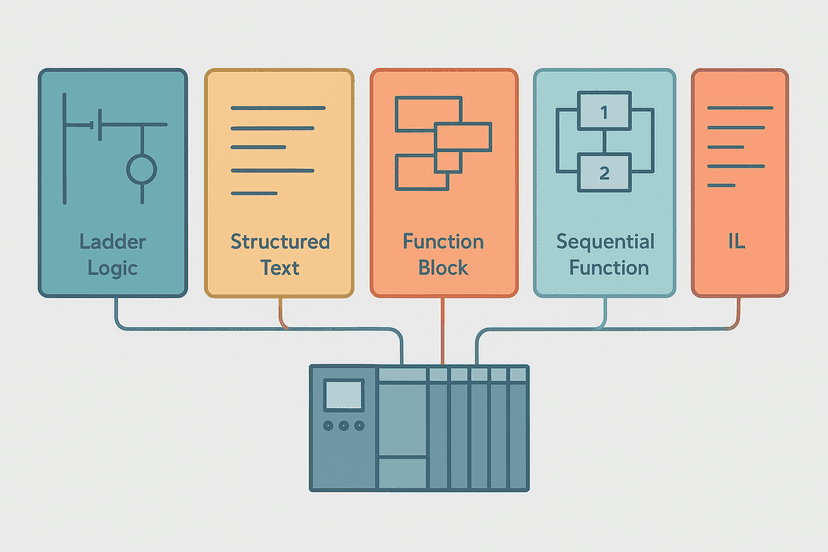
PLC Internal Bits: Flags, Coils and How to Use Them
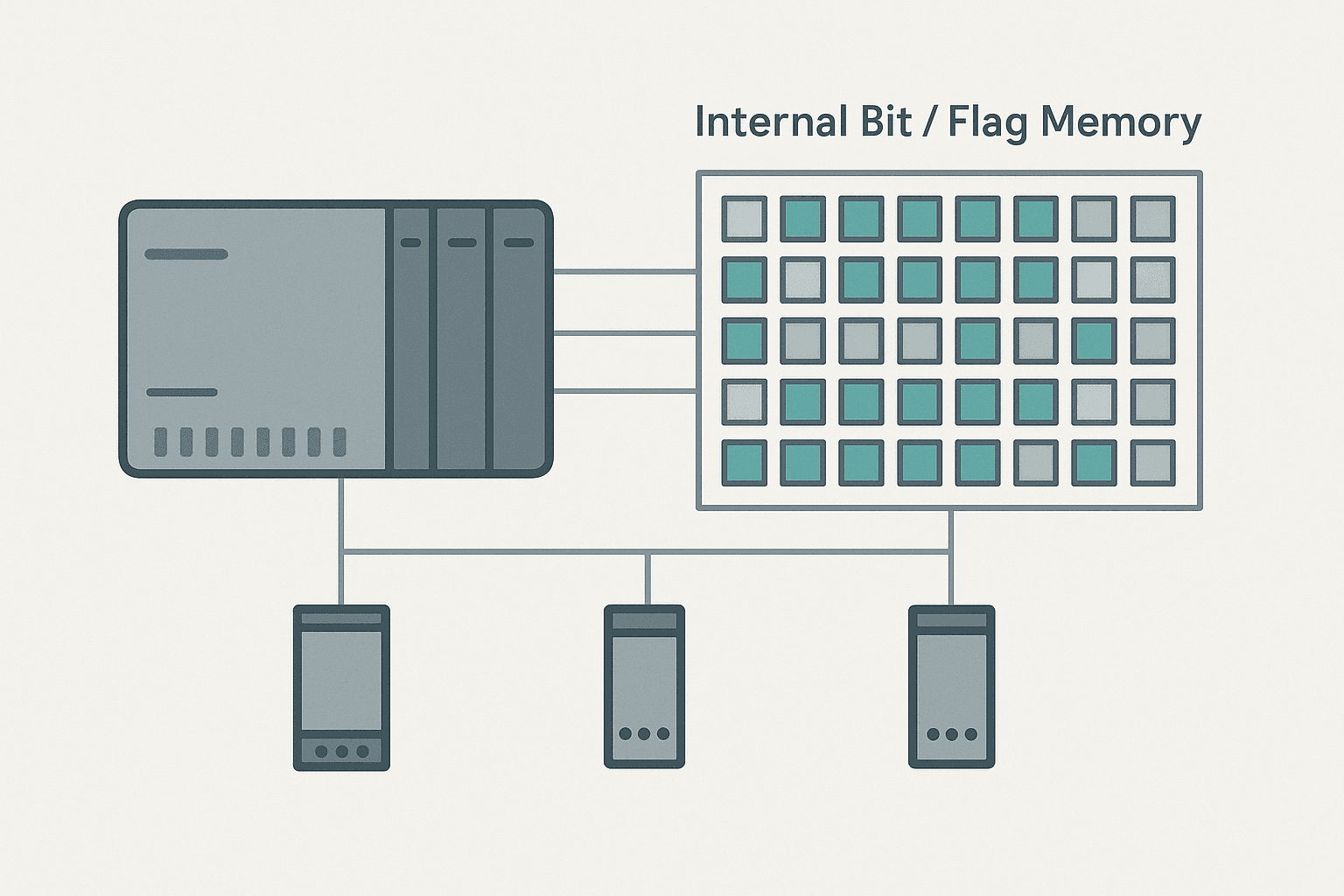
Every working PLC program uses internal bits constantly, yet they are almost never explained properly in beginner material. You get shown a start/stop motor rung and that is it. Nobody tells you what happens when your logic needs to communicate across 40 rungs, three program routines, and a fault-handling section. The answer, every time, is internal bits.
What Is a PLC Internal Bit?
A PLC internal bit is a single binary memory location (TRUE or FALSE, 1 or 0) inside the CPU that has no connection to any physical I/O terminal. Logic in one rung writes to it using a coil instruction. Logic in any other rung reads it using a contact instruction. It behaves exactly like a physical relay coil and contact pair, except nothing in the field switches. Internal bits are also called flags, marker bits, M bits, internal relays or, in older Allen-Bradley systems, B3 bits.
Why Internal Bits Exist
A PLC scan reads inputs, executes logic, then writes outputs, one full cycle at a time. See PLC scan cycle problems for why the scan order matters. The problem is that real processes have conditions that span multiple rungs: a conveyor may need to know that a downstream zone is clear, a batch process cleared its fault, and an operator confirmed the start, all at once. Wiring all of that through physical I/O every time would be absurd. Internal bits are the wires between rungs.
They also let you separate concerns cleanly. One rung decides if a condition is true and writes a bit. Many other rungs consume that bit. Change the decision logic in one place and every consumer updates automatically. This is the foundation of any maintainable program.
How Internal Bits Are Addressed Across Platforms
The concept is universal. The naming is not. Here is how the main platforms handle it:
| Platform | Address style | Example | Notes |
|---|---|---|---|
| Siemens S7 (TIA Portal) | Merker bit: M[byte].[bit] | M4.3 | MW, MD give byte/word access. Retain range set in CPU properties. |
| Rockwell Logix (Studio 5000) | Named BOOL tag | Conveyor_Ready (BOOL) | Stored in Controller Tags or Program Tags. No fixed address. |
| Rockwell SLC 500 / MicroLogix | B3:[word]/[bit] | B3:2/7 | Default file is B3; extra files (B9, B10) can be added. |
| Mitsubishi (GX Works3) | Auxiliary relay M | M100 | M0-M7679 standard; SM area for system flags. See [GX Works3 guide](/blog/mitsubishi-gx-works3-getting-started-guide). |
| CODESYS / Beckhoff | Declared BOOL variable | bConveyorReady : BOOL | Scope determines visibility: local, global or persistent. |
| Omron Sysmac | Internal relay W bit | W0.00 | W area is non-retentive; H area holds through power cycle. See [Omron Sysmac Studio guide](/blog/omron-sysmac-studio-getting-started-guide). |
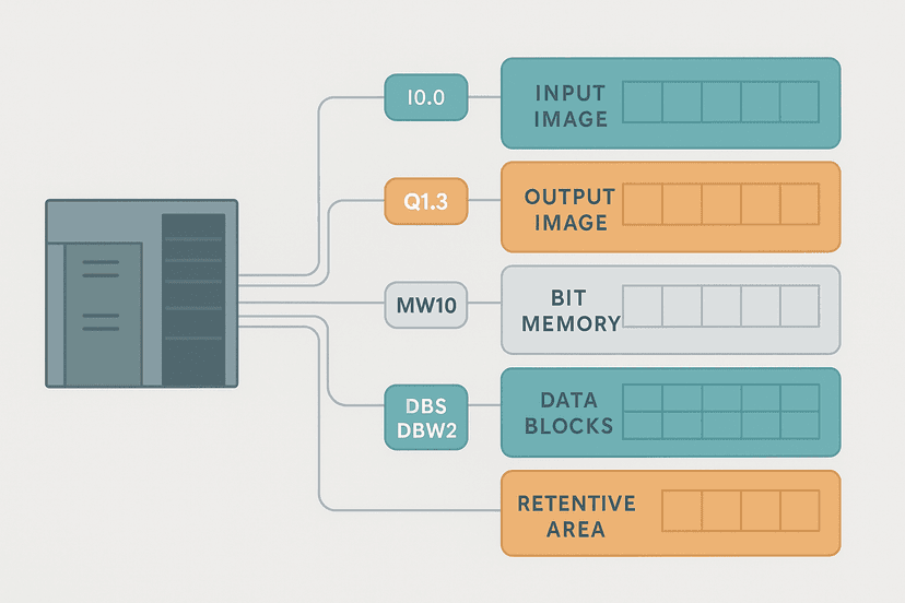
If you want to go deeper on how memory is organized behind these addresses, PLC memory and addressing explained covers the full picture including integer files, data tables and tag databases.
Internal Bits in Ladder Logic: What the Instructions Look Like
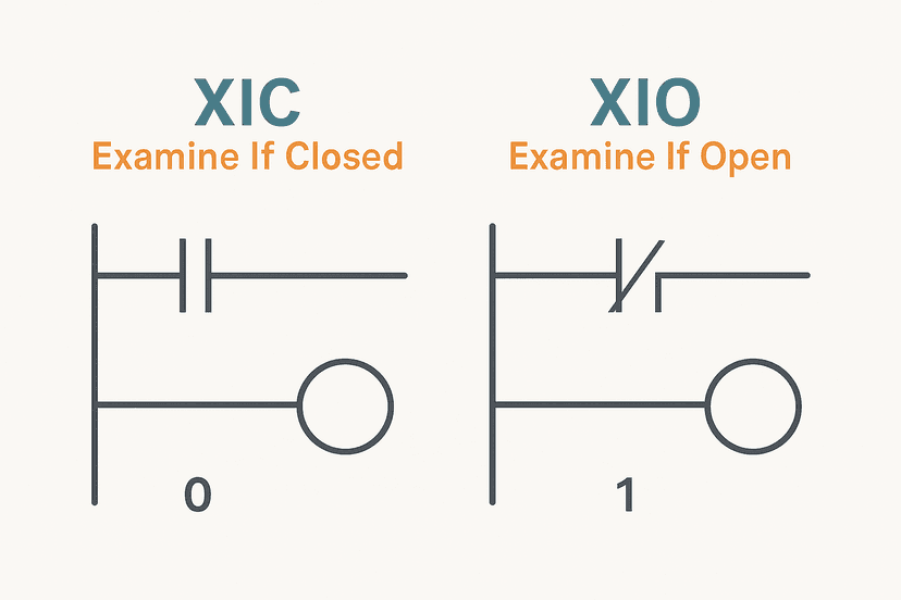
In Rockwell Logix (Studio 5000) you write to an internal BOOL tag with OTE, OTL or OTU, exactly the same instructions you would use for a physical output. The only difference is the tag name maps to CPU memory, not an output card channel. You read it back with XIC or XIO in any rung in any routine.
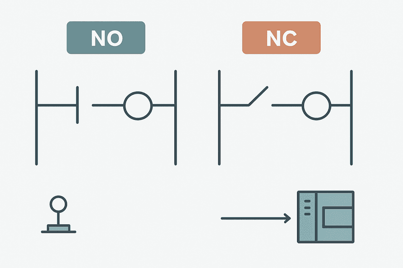
In Siemens TIA Portal you use the standard coil ( ) or SET/RESET coils. Writing to M4.3 with a coil sets that Merker bit. An NO contact on M4.3 anywhere in the program reads it. For the difference between NO and NC contacts and when to use each, see XIC vs XIO explained and the deeper look at NO vs NC contacts in ladder logic.
Oven Zone Ready: Multi-Condition Internal Flag with Fault Guard (Studio 5000). Ladder logic (4 rungs): Rung 0: examine if Oven_TempAtSetpoint is on (XIC), then examine if Exhaust_Fan_Running is on (XIC), then examine if Door_Confirmed_Closed is on (XIC), then examine if Oven_FaultLatch is off (XIO), then energize output Oven_Zone_Ready (OTE). Rung 1: examine if Oven_Zone_Ready is on (XIC), then examine if HMI_OvenStart is on (XIC), then latch output Oven_Cycle_Active (OTL). Rung 2: examine if HMI_OvenStop is on (XIC), then unlatch output Oven_Cycle_Active (OTU). Rung 3: examine if Oven_Cycle_Active is on (XIC), then energize output Product_Feed_Enable (OTE). Rung 1 combines four conditions into one internal BOOL tag Oven_Zone_Ready. Rungs 2 and 3 use that single bit to latch and unlatch the cycle. Rung 4 consumes it downstream to enable the product feed. If any of the four input conditions drops out, Oven_Zone_Ready goes FALSE and every downstream consumer responds immediately, without duplicating the four-condition check everywhere.
The diagram above evaluates one scan. Run these exact rungs on a real scan cycle to watch the latching and the timers behave.
Run this in the simulatorRetentive vs Non-Retentive: The Bit That Would Not Clear
This is the one that bites people hardest on commissioning. A retentive internal bit holds its value through a CPU power cycle. A non-retentive one clears to 0 on restart. By default in TIA Portal, Merker bits are non-retentive unless you declare them in the retentive Merker range under CPU properties. In Logix, a normal BOOL tag is non-retentive by default.
I once spent two hours on a food-processing line trying to understand why a batch fault alarm kept appearing on power-up even though the process was fine. The Merker bit holding the fault latch had been accidentally placed in the retentive range during a hardware config change two weeks earlier. After a planned power cycle the bit woke up TRUE, the alarm fired, and the operator called me at 6 a.m. One checkbox in CPU properties caused the whole thing. Always verify your retentive range boundaries before you go live.
The Duplicate Coil Problem
Because internal bits are so easy to create, programs accumulate them quickly. The trap is writing to the same bit in two separate rungs. Both rungs execute every scan. Whichever runs last wins. If rung 40 sets your bit TRUE and rung 80 has a condition that sets it FALSE, you will see the bit flicker or stay FALSE regardless of what rung 40 says. It looks like a logic bug, but it is a duplicate coil conflict.
Studio 5000 will warn you about duplicate OTE coils in its verify dialog. TIA Portal's compile check flags duplicate coils too. Use the cross-reference feature in whichever tool you are in to see every location that writes to a given tag. This becomes critical during troubleshooting. PLC troubleshooting with online monitoring covers how to use the cross-reference and online watch table together to track a misbehaving bit in real time.
Internal Bits vs Timer and Counter Bits
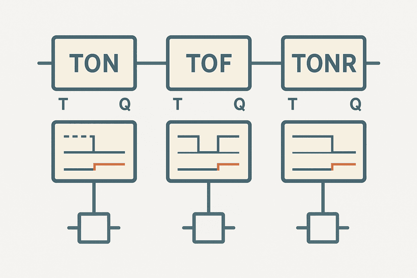
Timer and counter instructions produce their own internal status bits: the .DN (done), .TT (timer timing) and .EN (enabled) bits on a TON block, for example. These are a special category of internal bit because they are owned by the instruction, not freely declared by you. You can read them with XIC/XIO contacts anywhere, but you should never write to them directly. For a full breakdown of how timer bits work, TON, TOF and TONR timers and TON vs TOF vs TP cover the status bit behavior in detail. Counter instruction bits work the same way, covered in PLC counter instructions: CTU, CTD and CTUD.
System and Special Function Bits
Every platform reserves a set of internal bits for system use. These are read-only (mostly) and give you information about the CPU state. Common examples:
- First-scan bit: TRUE only on the very first scan after a CPU restart. Use it to initialize latches, clear accumulators, and set default states. In Logix it is S:1/15 (SLC) or the FirstScan tag (Logix 5000). In TIA Portal it is SM0.1 (S7-200) or a startup OB for S7-1200/1500.
- Always-on / Always-off bits: TRUE or FALSE every scan, handy for forcing coils or testing. Logix has no dedicated always-on bit, but you can create one with a simple OTE rung. Mitsubishi provides SM400 (always ON) and SM401 (always OFF) in the SM area.
- Clock bits: 1-second, 0.5-second, 0.1-second oscillating bits for blinking indicators or timed sequences without a full timer instruction. Mitsubishi SM412 (1 s clock), Siemens M254.0-M254.7 (configurable clock bits in CPU properties).
- Battery / memory error bits: Read these to detect a failed backup battery before the retentive data is lost. Critical on any machine that relies on retentive recipe values.
Practical Naming Conventions That Save You Later
In tag-based systems (Logix, TIA Portal, CODESYS) you choose the name, so make it count. A tag called B3:4/11 tells you nothing. A tag called Oven_Zone_Ready tells you everything. The conventions that work best in practice:
- Prefix with the subsystem: Oven_, Conveyor_, Batch_.
- Suffix with the bit type: _Ready, _Active, _FaultLatch, _Cmd, _FB (feedback), _Enable.
- Avoid abbreviations that only you understand. The technician at 2 a.m. will not know what 'OF_RDY' means.
- Separate internal command bits from physical I/O bits clearly, even if both are BOOL. A common scheme is to reserve tags ending in _Out or _In for I/O-mapped addresses only.
If you are working on a Siemens platform, TIA Portal Data Blocks gives you another option: storing related internal bits together in a structured DB, which makes them much easier to monitor as a group on an HMI. The S7-1200 Data Blocks: Global vs Instance DB post shows exactly when to put bits in a global DB versus keeping them as Merker bits.
Internal Bits Across Program Routines and Tasks
In Logix, Controller Tags are global: any routine in any task can read or write them. Program Tags are local to one program. If you write an internal BOOL to a Program Tag and try to read it in a different program, you will get a compiler error or, worse, a silent read of zero. This is a common trap when a project grows and someone adds a second program without checking tag scope.
In CODESYS and Beckhoff TwinCAT, global variable lists (GVL) serve the same role as Controller Tags. Local variables declared in a POU are not visible outside it. Plan your scope before you start writing hundreds of bits, not after.
A Note on Using Too Many Internal Bits
It is possible to over-use them. A program full of hundreds of intermediate bits becomes hard to follow because you are constantly jumping between the rung that writes the bit and the rungs that read it. Before adding another internal bit, ask whether the condition can simply be wired in series or parallel on the rung that needs it. Use a bit when the same condition is consumed in three or more places, or when the condition is complex enough that writing it once and naming it clearly is genuinely better. Fewer bits, clearer names, maintainable code.
For hands-on practice with internal bits in a real application context, the PLC bottle filling machine project and 3-motor start sequence exercise both make heavy use of internal flags for sequence state tracking and fault latching.
Keep Learning
Internal bits work hand-in-hand with contacts and coils, so if any of the contact types felt unclear, XIC vs XIO: Ladder Logic Contacts Explained and NO vs NC Contacts in PLC Ladder Logic are the right next reads. Once you are comfortable with bits and contacts, the natural next step is understanding how PLC memory and addressing organizes all of these elements, integers, timers, and bits into a coherent structure you can navigate confidently on any platform.
Frequently asked questions
What is an internal bit in a PLC?
What is the difference between an internal coil and an output coil?
How are internal bits addressed in Siemens S7 PLCs?
What are B3 files in Allen-Bradley PLCs?
Can I use internal bits to replace physical output signals?
Why would an internal bit stay TRUE after the machine stops?
What is the difference between a retentive and non-retentive internal bit?
How many internal bits can a typical PLC hold?
Are internal bits the same as flags?
What happens if two rungs write to the same internal bit?
Now build it
You have just read about XIC and XIO and OTE. Reading a rung and making one behave are different skills, and the second one is the job.
Start / Stop Circuit
Beginnerabout 10 minThe first circuit every controls engineer learns: a motor that starts on a button press, keeps running when the button is released, and stops on a stop button, with stop always winning.
Build this rungFree, no signup, runs in your browser. See all 16 exercises.
Was this helpful?