How PLC Input and Output Modules Work
Most engineers can describe what a PLC does at the system level. Far fewer can explain what physically happens inside the module when a push button closes or a solenoid valve energizes. That gap matters, because the I/O module is where almost every commissioning headache and field fault actually lives. Understanding the hardware saves you hours of guessing.
What Are PLC Input and Output Modules?
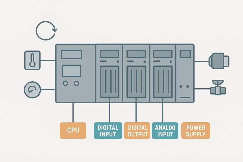
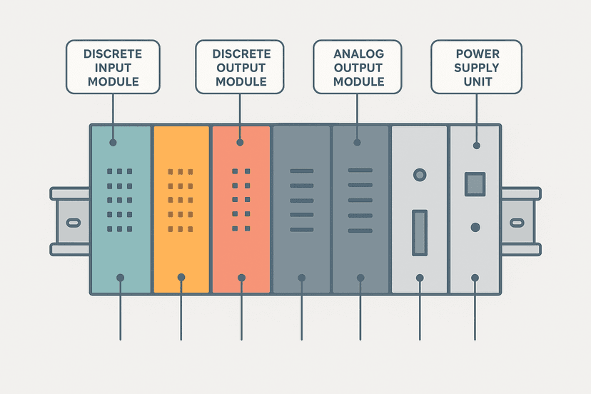
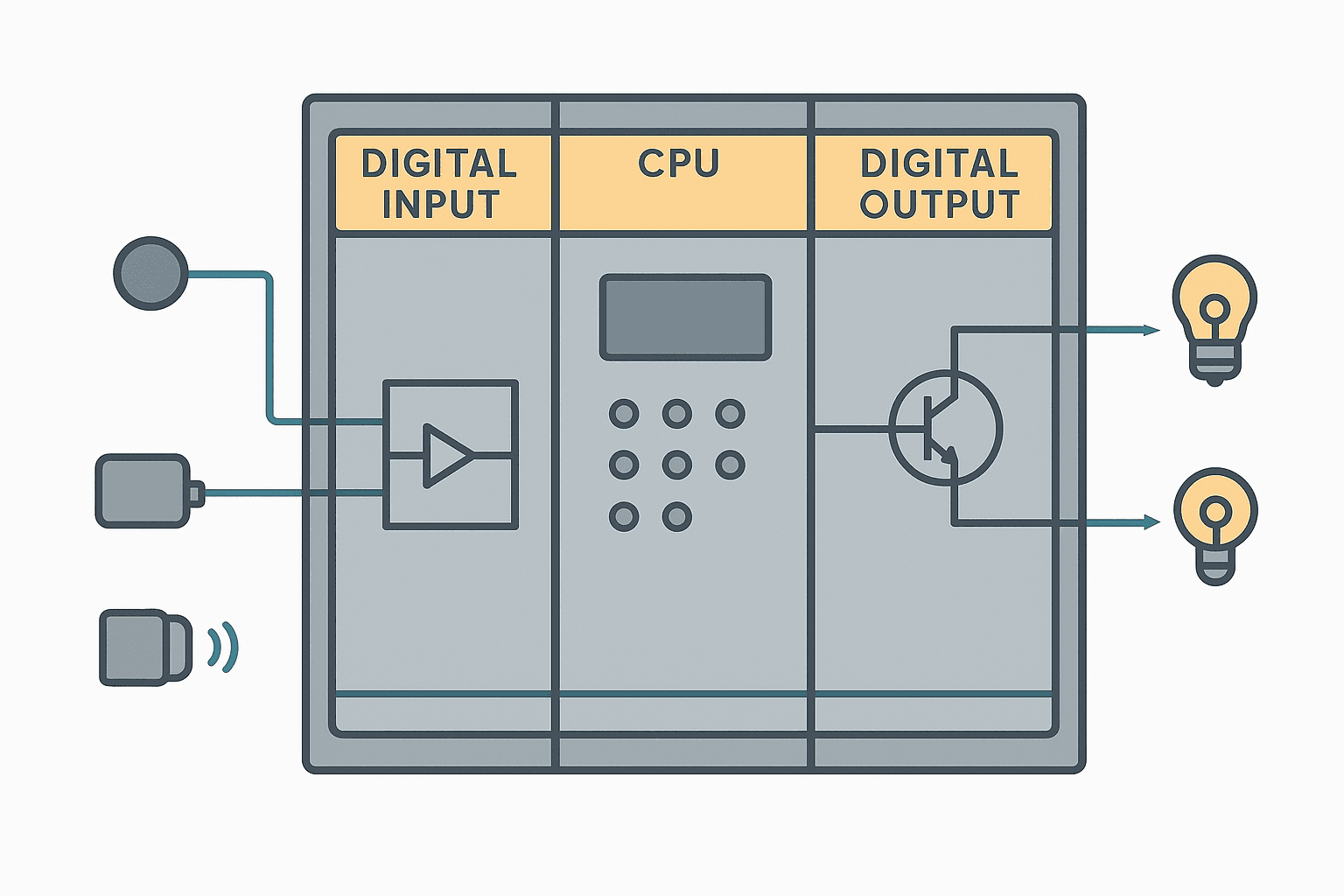
PLC input and output modules are the hardware interface between the CPU and the physical world. An input module converts a field voltage signal (from a sensor, switch, or transmitter) into a logic-level bit or integer value that the CPU can read. An output module takes a logic-level command from the CPU and converts it into a voltage or current capable of driving a real load, such as a relay coil, valve solenoid, or indicator lamp. Without these modules, the CPU has no way to sense or control anything outside its own rack.
Inside a Digital Input Module: From Field Wire to CPU Bit
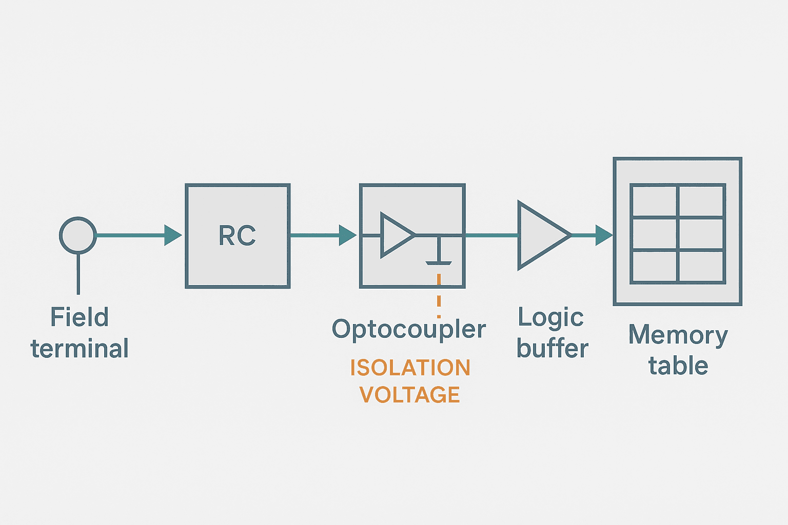
When a field voltage arrives at the module's terminal, it does not go straight to the processor. It goes through three stages first.
- Input filter (RC network). A resistor-capacitor filter smooths out high-frequency noise and contact bounce. The filter delay is usually 1 to 10 ms, configurable in software on most modern modules. Set it too long and you will miss fast pulses; set it to zero and electrical noise can cause false triggering.
- Optocoupler (optical isolation). The filtered signal drives an LED inside the optocoupler. The LED shines on a phototransistor on the CPU-side, turning it on. There is no electrical connection between field and CPU circuits, typically isolated at 500 V to 1500 V. This is what protects the processor from wiring faults and surges.
- Logic-level conversion. The phototransistor output is pulled up or down to a clean logic HIGH or LOW. That single bit is written into the input image table at the start of the next scan.
This is why two-wire (NAMUR-style) sensors can cause phantom ON readings. They pass a small leakage current even when off, and if that current is large enough to partially forward-bias the optocoupler LED, the module sees a weak HIGH. The fix is usually a bleed resistor across the input terminal to pull the leakage current to ground before it reaches the coupler. If you have not seen this one in the field yet, you will.
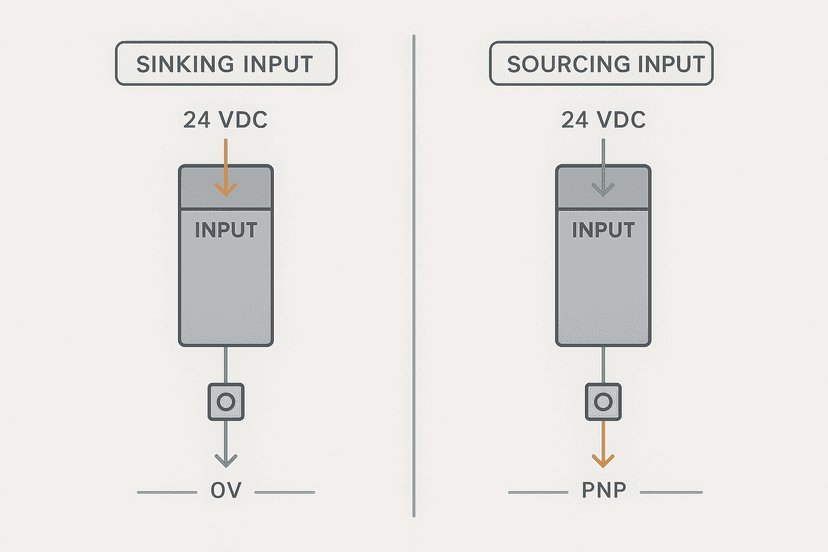
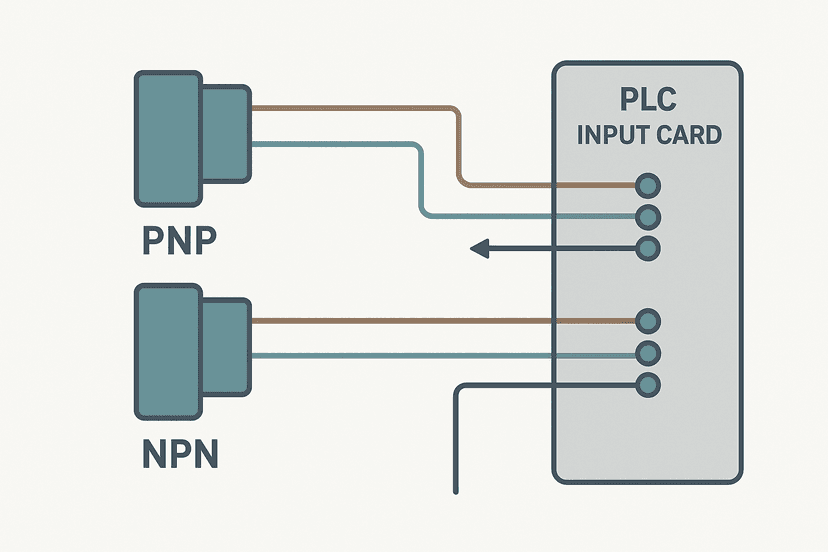
The wiring polarity of the module matters just as much as the voltage level. Whether you wire a sinking or sourcing configuration determines which way current flows through the optocoupler. Getting it wrong means the input never turns on at all, or it turns on permanently. And if you are connecting a three-wire PNP or NPN proximity sensor, the wiring rules are slightly different again, which is covered in detail in 3-Wire Sensor Wiring: PNP vs NPN to PLC Inputs.
The Input Image Table: Why the CPU Never Reads Live Field Values
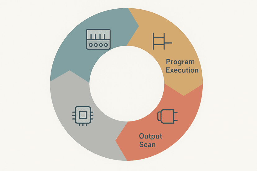
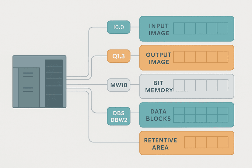
At the very start of each scan, the CPU reads every input module and copies the current state of each input bit into a dedicated block of memory called the input image table. For the rest of that scan, your ladder logic reads from this table snapshot, not from the physical terminals. This is a deliberate design choice. It guarantees that a single scan executes with a consistent, frozen view of the world. If the CPU read inputs live, a sensor changing state halfway through the scan could cause different rungs to see different values for the same input, producing logic that is almost impossible to debug.
The flip side is that any input event shorter than one scan cycle can be missed entirely. On a fast machine with a 10 ms scan and a 5 ms pulse, you need either a high-speed input module with its own latch register or a software pulse-stretching technique. This scan cycle behaviour is explained thoroughly in How the PLC Scan Cycle Works: Step by Step, and the timing problems it creates are covered in PLC Scan Cycle Problems: Logic and Timing Faults.
Inside a Digital Output Module: From CPU Bit to Field Voltage
At the end of the scan, the CPU writes the output image table to the physical output modules. Inside the module, the process is the mirror image of an input module: a logic-level signal drives the output switching device, which then controls the field load. The switching device is what defines the output module type.
| Output type | Switches | Speed | Typical load current | Key limitation |
|---|---|---|---|---|
| Relay | AC or DC | 10-20 ms | 2-5 A per point | Mechanical wear, limited switching cycles |
| Transistor (NPN/PNP) | DC only | < 1 ms | 0.5-2 A per point | Voltage drop ~1 V, DC loads only |
| Triac | AC only | < 1 ms | 0.5-1 A per point | Leakage current when off (~3-10 mA) |
Relay outputs are the workhorse of industrial panels because they switch any voltage and have genuine galvanic isolation. But on a machine that cycles a small solenoid thousands of times per shift, a relay output module will wear out in months. Transistor outputs are the right call there, and they are common on Siemens S7-1200 signal boards and Allen-Bradley Compact I/O modules in 24 VDC systems. Triac outputs appear mostly in older AC-controlled machines and HVAC applications.
Analog Input Modules: From Milliamps to Integer Counts
A digital input module cares about only two states. An analog input module has to measure a continuous signal with precision. The typical field signal is 4-20 mA (current loop) or 0-10 VDC. Inside the module, an analog-to-digital converter (ADC) samples the signal at a set rate (often 10 to 100 samples per second, depending on the module) and produces an integer count that the CPU stores in a word-sized input register.
On Siemens S7-1200 and S7-1500 modules, a 4-20 mA signal maps to a normalized integer range of 0 to 27648. On Allen-Bradley ControlLogix and CompactLogix modules, the same signal maps to 3277 to 16383 in raw mode, or 0.0 to 100.0 percent in engineering units mode. You have to know your platform's convention before you can write a scaling formula. The 4-20 mA Scaling Formula: The PLC Engineer's Guide has the numbers for both, and if you want to see the structured text and ladder code side by side, check 4-20 mA Scaling in a PLC: ST and Ladder Code.
Analog modules also have their own filtering, typically a configurable digital filter with a time constant between 0 and several hundred milliseconds. A long filter constant smooths out process noise but adds lag. On a flow measurement feeding a PID loop, too much filter delay will make the loop hunt. On a temperature reading where nothing changes faster than a few seconds, you can afford more filtering.
How Modules Map to CPU Memory
Every module slot in a PLC rack gets a fixed block of memory assigned to it. On a classic Siemens S7 system, digital inputs start at byte I0.0 and increment by module. On Allen-Bradley, a ControlLogix chassis assigns each module a tag structure under the module's name in the I/O tree. The exact addressing scheme depends on the platform, but the concept is the same: the physical slot position determines the memory address.
This is why pulling a module out of the wrong slot during a live swap can trigger faults in completely unrelated parts of the program. If your plant uses remote I/O over PROFINET or EtherNet/IP, the same mapping principle applies, but now the slot numbers exist in a network device rather than a local rack. Understanding PLC Memory and Addressing Explained gives you the full picture of how these addresses fit into the broader memory model, and PLC Addressing Modes: Direct, Indirect and Symbolic shows how your program actually references those locations.
Common I/O Module Faults and What Causes Them
In practice, I/O modules fail in predictable ways. Knowing the mechanism makes diagnosis much faster. Here are the ones you will hit most often:
- Blown output transistor. Usually from an inductive load (solenoid, relay coil) without a freewheeling diode. The kickback spike exceeds the transistor's voltage rating. One point fails shorted or open while the rest of the module works fine.
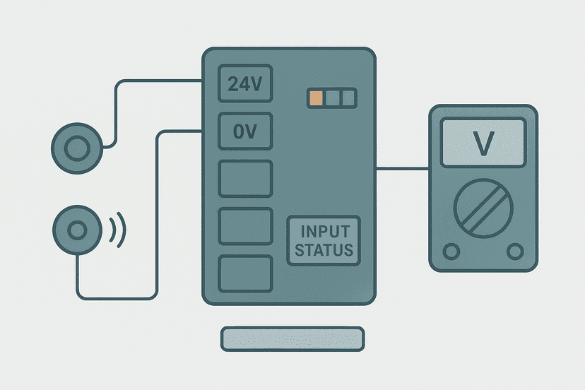
- Input stuck ON. Two-wire sensor leakage, a wiring short, or a failed optocoupler. Use a multimeter at the input terminal to check whether the field voltage is actually present, as described in PLC I/O Fault Diagnosis with a Multimeter.
- Analog channel drifting or reading zero. Broken shield on the signal cable, intermittent loop power supply, or a failed transmitter. The PLC Analog Output Faults: How to Diagnose Them post covers the output side of this, and Shielding Analog Signal Cables in PLC Panels explains how poor shielding causes erratic readings.
- Module channel fault bit set. Most modern modules report individual channel faults to the CPU. On Allen-Bradley Compact I/O, this appears as a bit in the module's fault tag. On Siemens, it surfaces in the diagnostic buffer. Always check the module's own fault reporting before blaming the field device.
- Input LED on, bit not set in CPU. The module is powered and the field voltage is present, but the CPU is not reading it. Check the module's configuration in the project (is the channel enabled?), the module's fault status, and whether the module is in the correct rack slot.
For a systematic approach to any of these, PLC Digital Input Faults: How to Diagnose Them and PLC Output Faults: How to Diagnose Them Fast walk through each scenario with test steps. If you want to start with the broadest diagnostic method, PLC Fault Finding: A Systematic 6-Step Method is the right starting point.
A Note on Module Types Beyond Basic I/O
Digital and analog are the two categories most engineers deal with daily, but modern PLC racks also accommodate specialty modules: high-speed counter modules for encoder feedback (up to 1 MHz on some platforms), temperature input modules with built-in thermocouple or RTD linearization, motion control axes modules, and communication modules for PROFINET, EtherNet/IP, Modbus, and others. Each of these follows the same fundamental principle: map field data into CPU memory, or write CPU commands to field hardware. Types of PLC Modules: I/O, Comms and More covers the full catalogue if you need to spec out a system from scratch.
Keep Learning
Now that you understand what happens inside the module, the logical next step is understanding how the CPU orchestrates all of this on every scan. How the PLC Scan Cycle Works: Step by Step picks up exactly where this post leaves off. From there, PLC Memory and Addressing Explained will show you how those input and output bits live inside the CPU's memory map, and What Is a PLC Controller and How Does It Work? ties the whole architecture together.
Frequently asked questions
What does a PLC input module actually do?
Why do PLC I/O modules use optical isolation?
What is the I/O image table in a PLC?
What is the difference between relay, transistor, and triac output modules?
Can one PLC input module handle both AC and DC sensors?
How does an analog input module differ from a digital input module?
Why is the output image table updated at the end of the scan and not immediately?
What causes PLC input modules to read false ON states?
How many outputs can one PLC output module drive?
Learn this by building it
There is a PLC in this site. It runs a real scan engine, checks your logic against the same tests a working machine would fail, and needs no download and no account.
Open the exercisesFree, no signup, runs in your browser. See all 16 exercises.
Was this helpful?