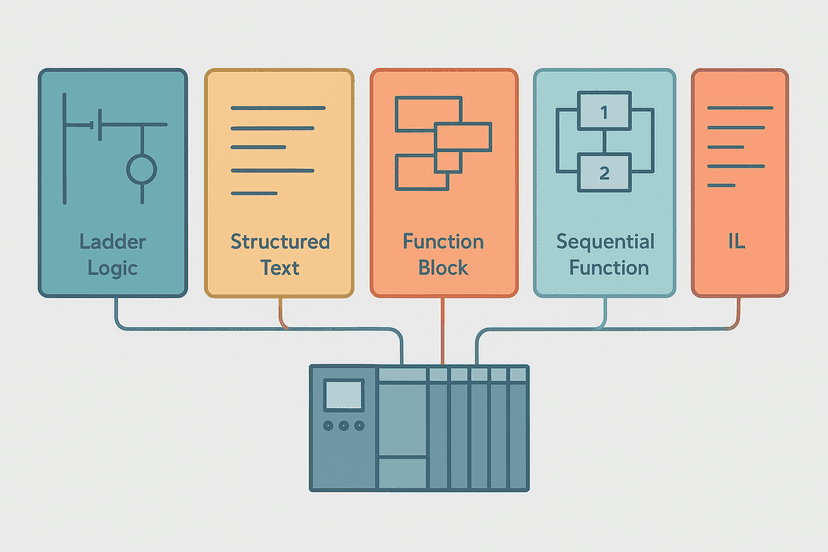
PLC Addressing Modes: Direct, Indirect and Symbolic
Every instruction in a PLC program has to know where to find its data. The method it uses to locate that data is the addressing mode. Pick the wrong mode and you end up with logic that works on one hardware layout but breaks the moment a module moves, a recipe grows, or a technician needs to read the code six months later. Understanding all three modes, direct, indirect and symbolic, is one of those fundamentals that separates engineers who write maintainable programs from those who write ones nobody wants to touch.
What Are PLC Addressing Modes?
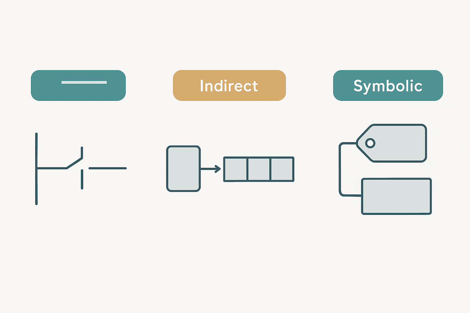
PLC addressing modes are the methods a controller uses to locate a specific memory cell during program execution. The three core modes are direct (a fixed, hard-coded address), indirect (an address computed at runtime from a variable), and symbolic (a named tag resolved to an address at compile time). Each mode trades off simplicity, flexibility and readability in a different way, and IEC 61131-3 acknowledges all three in its data model even though vendors implement them differently.
Direct Addressing: Simple, but Brittle
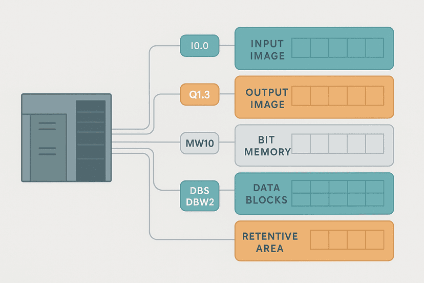
Direct addressing hard-codes the memory location right into the instruction. In RSLogix 500 it looks like I:1/5 (input file 1, word 0, bit 5) or N7:0 (integer file 7, element 0). In CODESYS or IEC 61131-3 absolute notation you see %IX0.5 for input byte 0 bit 5, or %MW10 for a memory word. The CPU goes straight to that address, no calculation, no indirection.
The advantage is transparency. You can look at the address and know exactly which physical terminal you are reading. That is why direct addressing is still common in simple panel retrofits and in quick diagnostic rungs where you need to force a specific I/O bit in a hurry.
The downside is brittleness. Move a module from slot 2 to slot 3 and every hard-coded I:2/x reference in the program breaks. On a 2,000-rung program that is a painful global find-and-replace session. I've seen technicians on a weekend shift move an analog card to free up a slot, not realise the addresses shifted, and then spend four hours chasing a phantom fault that was actually a wrong input file number. Direct addressing is also nearly impossible to read without the I/O list open in front of you.
I: and O: file references, at least alias every one of them to a named symbol in the symbol table. It costs 20 minutes up front and saves hours every time the hardware changes.Symbolic Addressing: The Modern Standard
Symbolic addressing replaces the raw address with a human-readable name. The compiler or download process resolves that name to a physical address once, and the CPU uses the resolved address every scan. From a runtime performance standpoint it is identical to direct addressing.
Studio 5000 (Logix5000) uses symbolic tags as its native model. Every tag you create, Conveyor_Run, Tank_Level_PV, Recipe_Index, is stored in the tag database and referenced by name in every rung. TIA Portal for the S7-1200 and S7-1500 also defaults to symbolic addressing, which is a big shift from the older S7-300/400 world where MW100 or DB5.DBW4 were the norm. If you are curious how the underlying memory is laid out, PLC Memory and Addressing Explained walks through the mechanics.
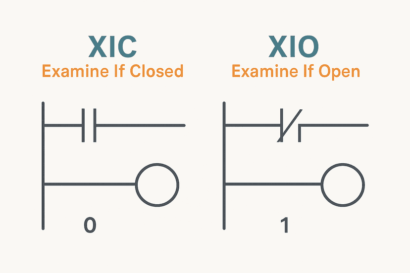
Symbolic addressing pays off in three ways. First, readability: XIC(Guard_Door_Closed) tells you what the contact means without opening any documentation. Second, portability: if the physical I/O address changes you update the tag definition in one place and every rung that references it updates automatically. Third, it integrates cleanly with HMI and SCADA tools that consume the tag database directly, which you can read about in HMI Tag Linking: Mapping PLC Addresses Correctly.

Indirect Addressing: Power for Recipes and Sequences
Indirect addressing uses a variable to compute or select the target address at runtime. The most common form in modern PLCs is array indexing: instead of reading Recipe[3].FillTime_ms you read Recipe[HMI_RecipeIndex].FillTime_ms, where HMI_RecipeIndex is an integer that the operator sets at the HMI. The instruction evaluates the index each scan and reads a different array element depending on its current value.
This is the backbone of multi-product machines. Without indirect addressing you need a separate set of rungs for each recipe, which means 10 recipes equals 10 copies of identical logic with different constants. That is a maintenance nightmare. With indirect addressing you write the logic once and let the index drive the selection. The same principle applies to step sequencers: store each step's output pattern in an array and index it with a step counter rather than a pile of CASE branches or duplicated rungs.
Indirect Addressing in Studio 5000
In Studio 5000 Logix you use square-bracket notation. If Setpoints is an array of REAL tags and Step_Index is a DINT, then Setpoints[Step_Index] is a valid indirect reference in any instruction that accepts a REAL operand. The controller will fault with a major fault type 04 if Step_Index goes below 0 or above the declared array size minus 1. Always clamp the index before you use it, typically with a LIM or a Structured Text IF block upstream.
Indirect Addressing in TIA Portal (S7-1200 and S7-1500)
The S7-1200 does not support the classic S7-300 pointer syntax (P#M0.0). Instead you use array indexing in Structured Text or SCL: DB_Recipes.Setpoint[RecipeIdx] where RecipeIdx is an INT variable. You can also do this from a ladder rung by calling an SCL function that handles the indexing and passes the result back. If you are building out your first S7-1200 project, S7-1200 First Program in TIA Portal covers the project structure you need before adding array logic. For larger programs, TIA Portal Data Blocks: DB Types and When to Use Each explains where to store your recipe arrays.
Indirect Addressing in CODESYS
CODESYS (and platforms based on it, such as Beckhoff TwinCAT and Phoenix Contact PLCnext) supports both array indexing and pointer-based indirect addressing under IEC 61131-3. Array indexing works identically to Logix: aSetpoints[iStep]. Pointer arithmetic with the ADR() function is available in Structured Text for advanced cases, but most applications never need to go beyond array indexing. Given that 5 Types of PLC Programming Languages Explained covers the full IEC 61131-3 set, it is worth reviewing which language best suits your indirection needs.
Indirect Addressing: A Ladder Logic Example
The following example shows a 4-step sequencer using an array-indexed output pattern in Studio 5000. Each step's output word is stored in SeqOutputs[0] through SeqOutputs[3]. The current step drives the index.
Array-Indexed Step Sequencer with TON Dwell and Auto-Advance (Studio 5000). Ladder logic (5 rungs): Rung 0: examine if Seq_Running is on (XIC), then examine if Seq_FaultLatch is off (XIO), then TON on Step_Dwell. Rung 1: examine if Step_Dwell.DN is on (XIC), then examine if Step_Advance_OS is on (XIC), then CTU on Seq_Step. Rung 2: examine if Seq_Step.DN is on (XIC), then unlatch output Seq_Running (OTU), then either RES on Seq_Step. Rung 3: examine if Step_Advance_OS is on (XIC), then RES on Step_Dwell. Rung 4: examine if Seq_Running is on (XIC), then MOV on SeqOutputs[Seq_Step]. Seq_Running enables the sequencer. Step_Dwell is a TON whose preset comes from SeqTimes[], a DINT array indexed by the current step number, so each step can have a different dwell time. When the timer finishes, a one-shot triggers CTU to increment Seq_Step. When Seq_Step reaches 4 (CTU.DN), the sequencer stops and resets. MOV copies the output bit pattern from SeqOutputs[], also indexed by Seq_Step, to Output_Word every scan. Clamp Seq_Step to 0-3 with a LIM rung before this block to prevent a major fault if the counter ever reaches its limit mid-cycle.
Comparing the Three Modes Side by Side
| Mode | Address resolved | Readable? | Flexible? | Fault risk |
|---|---|---|---|---|
| Direct | Hard-coded at program entry | Poor | Low | Hardware layout changes break all references |
| Symbolic | At compile / download time | Excellent | Medium | Rename in one place updates everywhere |
| Indirect (array index) | At runtime each scan | Good with naming | High | Out-of-range index causes CPU fault or data corruption |
Common Mistakes and Field Gotchas
Forgetting to clamp the indirect index. This is the most common indirect addressing bug. An operator enters a recipe number of 5 on an HMI that allows 0 to 4. The array has 5 elements (index 0 to 4). Index 5 is out of bounds. In Studio 5000 you get a major fault and the CPU stops. In TIA Portal the system reads adjacent memory, which may corrupt a completely unrelated variable without any obvious error message. Always add a LIM or MIN/MAX clamp before the instruction.
Mixing absolute and symbolic references to the same tag. In TIA Portal you can display both the symbolic name and the absolute address. Some engineers write one rung referencing %MW50 directly and another referencing the symbolic tag Tank_Setpoint that is also mapped to %MW50. If you later move the tag to %MW52, only the symbolic reference updates. The absolute reference silently reads the wrong location. Stick to one style throughout the program.
Using a BOOL array when you need a WORD bit-mask. Beginners sometimes create 16 separate BOOL tags for a step's output pattern instead of a single INT or DINT. Bit-packing into a word makes MOV-based indirect output patterns trivial. Sixteen individual BOOLs require 16 separate indirect reads per scan. It still works, but it is more complex and slower on older hardware.
Assuming indirect addressing is available everywhere. Some compact or entry-level PLCs don't support array indexing in ladder, only in ST or FBD. Check the instruction reference for your specific platform before designing a recipe system that depends on it. For platforms like the S7-1200, S7-1200 Data Blocks: Global vs Instance DB Explained clarifies where array data should live to be accessible from ladder and ST alike.
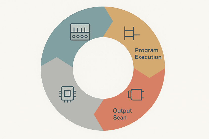
Understanding how the PLC resolves addresses each scan also connects directly to scan cycle behaviour. If your indirect index changes mid-scan, the value the instruction sees depends on where in the scan it executes. For the full picture on scan-order effects, How the PLC Scan Cycle Works: Step by Step is worth a read alongside this post.
Choosing the Right Mode for Your Application
- Use symbolic addressing for all general logic. It is the default in every modern platform and the right answer for 90% of rungs.
- Use indirect array indexing for recipe selection, step sequencers, multi-product machines, and any table-driven logic where the same calculation repeats across many data sets.
- Use direct absolute addressing only when you have a specific need to reference a raw hardware address, such as in a diagnostic rung or when integrating legacy hardware where the module's absolute address is fixed by hardware and cannot be changed.
- Always validate indirect indexes before use. A one-rung LIM check or a Structured Text clamp takes seconds to write and prevents major faults in production.
- Document your arrays. A comment block or a UDT (User-Defined Type) that describes what each element means is not optional when indirect addressing is involved, because the code by itself doesn't tell you what Recipe[2] represents.
If you are building your first multi-recipe machine, look at the PLC Bottle Filling Machine: Step-by-Step Project for a worked example of how recipe data flows from an HMI selection through PLC logic to physical outputs. The PLC Counter Instructions: CTU, CTD and CTUD Explained post also covers how to use a counter as a step index in a sequencer, which pairs naturally with array-indexed output patterns.
For troubleshooting programs that already use indirect addressing, PLC Troubleshooting with Online Monitoring shows how to watch the index variable live and confirm which array element is active during a fault condition. That visibility is what makes indirect addressing debuggable in the field.
What to Read Next
If you want to go deeper on how memory is structured before choosing an addressing mode, start with PLC Memory and Addressing Explained. Once your addressing strategy is set, PLC Internal Bits: Flags, Coils and How to Use Them shows how internal memory bits fit into the same addressing model. And if you are ready to apply all of this in a real project, PLC Pump Station Exercise: Ladder Logic gives you a full worked program to practice with.
Frequently asked questions
What is direct addressing in a PLC?
What is symbolic addressing in a PLC?
What is indirect addressing in a PLC and when should I use it?
Does the S7-1200 support indirect addressing?
Can you use indirect addressing in Studio 5000 Logix?
What happens if an indirect address index goes out of range?
Is symbolic addressing slower than direct addressing?
What is the difference between absolute and symbolic addressing in TIA Portal?
Can I mix addressing modes in the same PLC program?
Now build it
You have just read about CTU and CTD and CTUD. Reading a rung and making one behave are different skills, and the second one is the job.
Batch Counter (CTU + RES)
Intermediateabout 15 minCount parts passing a sensor; after 4 parts the batch is done and a lamp turns on. A reset button starts the next batch. Counters count RUNG EDGES: a part sitting on the sensor counts once, not forever.
Build this rungFree, no signup, runs in your browser. See all 16 exercises.
Was this helpful?