HMI Alarm Configuration: From Raw Bit to Useful Alert
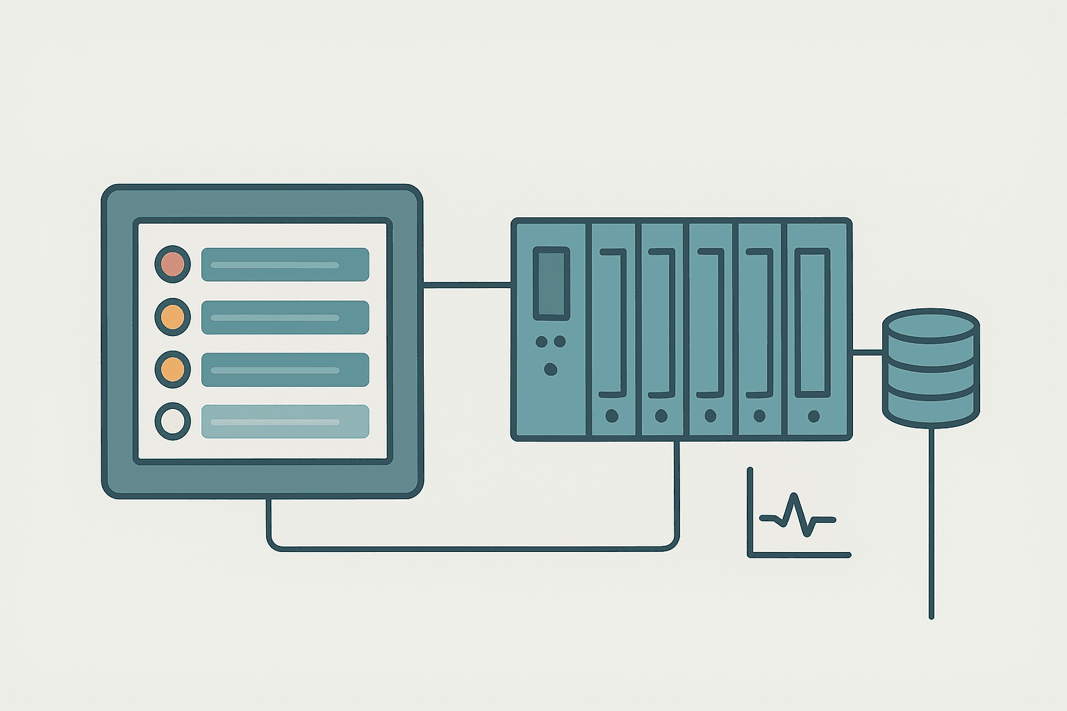
A lot of HMI alarm systems get built backwards. The developer exports every PLC fault bit, drops them into the alarm banner, assigns them all to priority 1, and calls it done. Six months into production the operators are ignoring the alarm screen entirely because it never stops flashing. That is not a plant problem, it is a configuration problem, and it is completely avoidable.
What Is HMI Alarm Configuration?
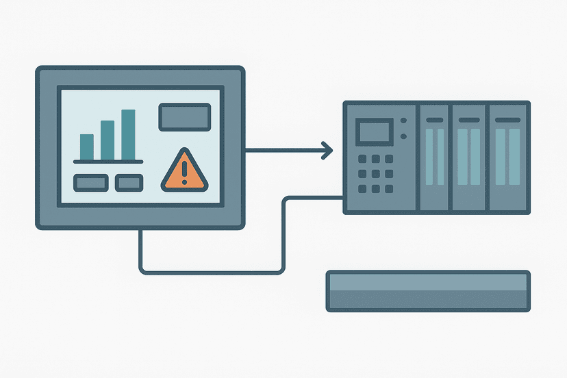
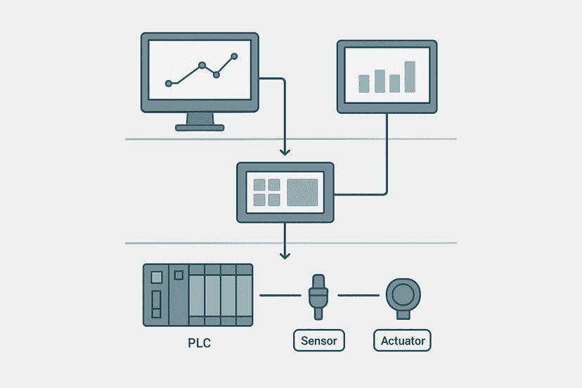
HMI alarm configuration is the process of defining, inside the HMI software project, which PLC tag values represent abnormal conditions, what priority each condition carries, how the HMI should display and log the alarm, and what acknowledgment workflow the operator must follow. It is separate from the PLC program itself: the PLC writes tag values, and the HMI evaluates those values against your configured thresholds. You can add or change alarm limits without touching a single rung of ladder logic.
Alarm Types: Discrete vs Analogue
Every HMI alarm belongs to one of two families. Understanding which type you need before you build saves a lot of rework.
Discrete alarms watch a single Boolean tag. The alarm activates when the bit goes TRUE (or FALSE, depending on configuration). Motor run-confirm faults, door-open interlocks, e-stop trips and communication loss flags are typical discrete alarms. They are the easiest to configure and the most common source of alarm floods when over-used.
Analogue alarms watch a numeric tag, usually an integer or real representing a process value like temperature, pressure or flow. You define one or more threshold levels: High (HI), High-High (HH), Low (LO) and Low-Low (LL). The alarm activates when the value crosses the threshold. Because process values drift and bounce, analogue alarms also need a deadband, covered below. For background on how raw counts from a 4-20 mA transmitter get converted to engineering units before the HMI even sees them, see the 4-20 mA scaling formula guide.
Setting Alarm Priorities: Keep It to Four Levels
Priority is the single most abused setting in HMI alarm configuration. The temptation is to make everything Critical so nothing gets missed. The result is that everything gets ignored.
| Priority | Typical Label | What It Means | Operator Response Time |
|---|---|---|---|
| 1 | Critical | Immediate safety or equipment risk, production stops | Within 1 minute |
| 2 | High | Significant process deviation, production at risk | Within 10 minutes |
| 3 | Medium | Process degraded, operator awareness needed | Within 1 hour |
| 4 | Low | Advisory, informational, log for review | Next shift or scheduled |
Assign Critical only to conditions that can hurt someone or destroy equipment within minutes if not acted on. E-stop faults, high-high temperature on a motor winding, PLC CPU faults and safety relay trips belong here. For guidance on diagnosing the CPU-side events that feed these alarms, the PLC CPU faults diagnosis guide is worth reading alongside your alarm rationalization work.
Deadbands: Stop Analogue Alarms from Chattering
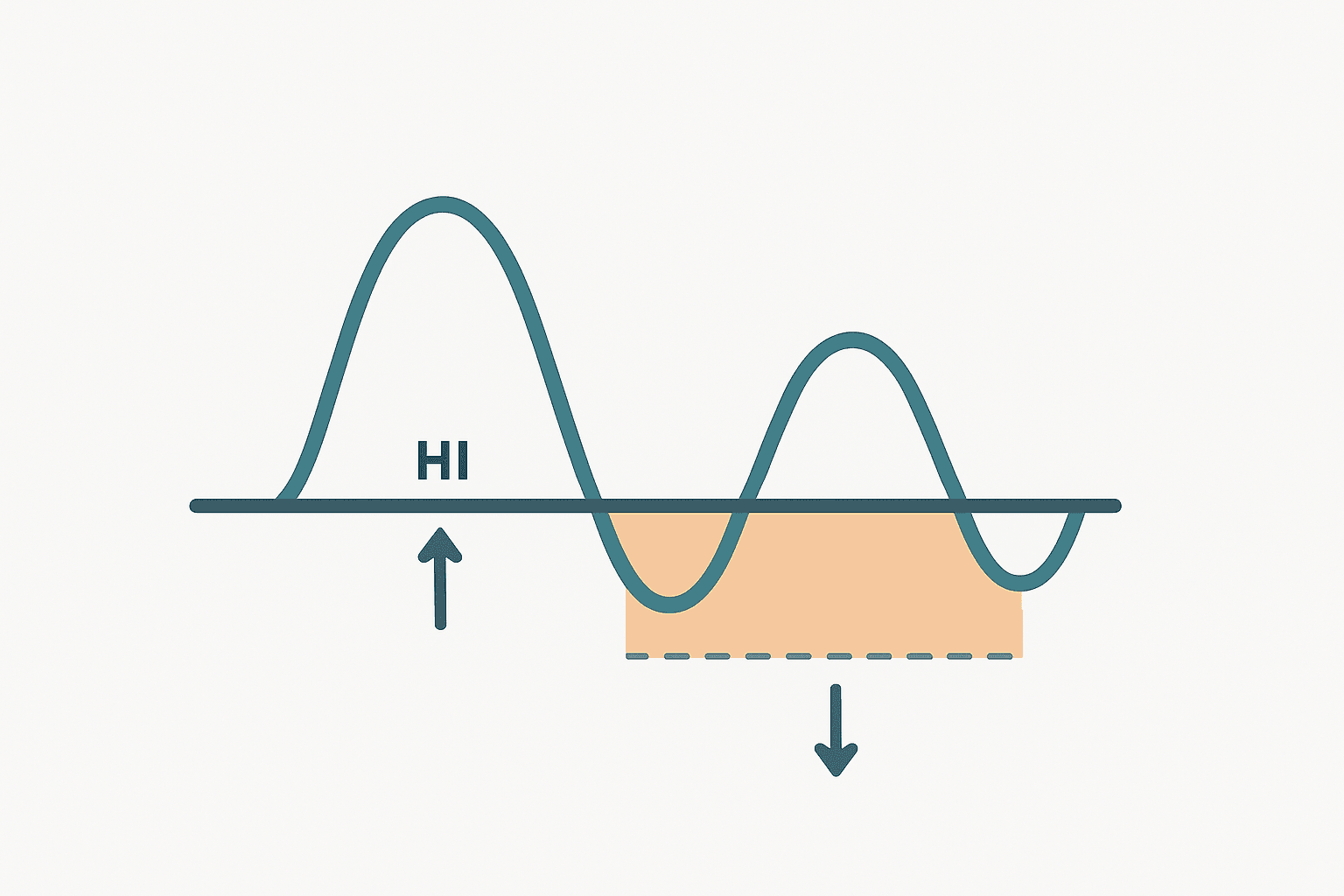
A process value sitting at exactly the alarm threshold will oscillate above and below it with normal signal noise. Without a deadband, the alarm triggers and clears dozens of times per minute, flooding the alarm log and training operators to ignore it.
A deadband creates a gap between the activate point and the reset point. If the High alarm is set at 80 degrees C with a 2-degree deadband, the alarm activates at 80 degrees C and does not clear until the value drops to 78 degrees C. That small gap eliminates chatter without masking a real sustained exceedance.
A practical starting point: 1 to 2 percent of the full engineering range for most analogue process alarms. A pressure transmitter spanning 0 to 10 bar with a High alarm at 8 bar should have a deadband of 0.1 to 0.2 bar. Increase it if the signal is noisy; never set it to zero.
On-Delay: Filter Out Transients Before They Become Alarms
Most HMI packages let you specify an on-delay, sometimes called an alarm delay or filter time. The alarm only activates if the condition persists for the full delay period. A 2-second delay on a motor run-confirm alarm prevents a nuisance trip during the motor's acceleration ramp. A 500 ms delay on a discrete position sensor alarm filters contact bounce without masking a real jam.
On-delays are especially useful on intermittent sensor faults where a marginal connection causes brief dropouts. The delay stops the alarm from firing every time the cable flexes, while still catching a genuine sustained fault.
Acknowledgment Workflow: Four States Every Alarm Passes Through
Getting the ack workflow right is where most HMI projects cut corners. An alarm cycles through four distinct states, and your display must show all four clearly:
- Unacknowledged, Active: condition is present AND the operator has not seen it yet. This is the most urgent state. Use a flashing red background or flashing text. Never suppress the flash.
- Acknowledged, Active: operator has seen it but the fault is still present. Steady red, no flashing. The operator knows and is working on it.
- Unacknowledged, Cleared: condition resolved before the operator acknowledged it. This is a common missed state. Use a steady amber or blue to distinguish it from an active alarm.
- Acknowledged, Cleared: normal state. The alarm disappears from the active list and moves to the history log.
The Unacknowledged, Cleared state is the one most HMI screens handle badly. If you flash red for both Active-Unacked and Cleared-Unacked, operators cannot tell if the fault is still happening. That distinction matters enormously during a fast-moving fault condition.
For the visual side of this, the HMI screen design guide covers colour conventions and layout rules that complement the alarm state logic described here.
HMI Alarm Configuration in Practice: TIA Portal WinCC
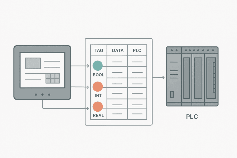
In TIA Portal, HMI alarms live under the HMI device in the project tree, not in the PLC program. You configure them in the Alarm Management editor. The workflow is: create a tag (linked to a PLC data block or I/O address), then define an alarm class, then configure the alarm trigger on that tag.
- Create HMI tags: map your PLC DB addresses or I/O addresses to HMI tags in the HMI tag table. The HMI tag linking guide covers the address mapping in detail.
- Define alarm classes: TIA Portal ships with Errors and Warnings by default. Add a Maintenance class for shelved or advisory alarms. Each class gets its own colour, ack group and log behaviour.
- Add discrete alarms: select the Boolean HMI tag, set Trigger Bit to 0 (the tag itself), set Trigger on Rising Edge for a normally-off fault bit. Assign priority and class.
- Add analogue alarms: select the numeric tag, set the High Limit value, set the Deadband (absolute or percentage), set the On-Delay in milliseconds, assign priority.
- Configure the alarm view control: drop an Alarm View or Alarm Window control onto your screen. Set it to show Active Alarms filtered by class. Add a separate History view for cleared alarms.
For a full walkthrough of TIA Portal HMI project structure, the HMI programming in TIA Portal guide gives the broader context. And if you are working with S7-1200 data blocks as the tag source, the S7-1200 data blocks guide explains the global DB addressing you will be mapping from.
Alarm Logging and the Historian Connection
Every alarm event, activate, acknowledge and clear, should be logged with a timestamp and operator ID. Most HMI packages write alarm logs to an internal buffer or a local database. On larger sites that log feeds a SCADA historian for long-term trend analysis and compliance reporting. The SCADA historian guide covers how that data pipeline works downstream.
Keep the log buffer large enough to hold at least 24 hours of alarm events at your expected alarm rate. If you are hitting 300 alarms per day (already too many by ANSI/ISA-18.2 standards, which suggest no more than 150 per day per operator), a 10,000-event buffer gives you only 33 days of history. Export regularly.
Alarm Rationalization: Build the Database First
Alarm rationalization means documenting every alarm in a spreadsheet before you configure it. For each alarm you record: tag name, alarm description, cause, consequence, operator response, priority and whether it needs acknowledgment. This takes discipline but it stops the most common mistake, which is configuring alarms because the data is available rather than because an operator needs to act on it.
If you are working on a site that already has an alarm flood problem, the SCADA alarm management guide covers the rationalization and flood-reduction process in depth, including how to identify and shelve standing alarms.
Common Mistakes That Create Bad Alarm Systems
- Mapping every PLC internal flag to an alarm: most internal bits are logic state variables, not operator alerts. See the FAQ below for the rule of thumb.
- No deadband on analogue alarms: any process signal with noise will chatter without one.
- All alarms at the same priority: when everything is critical, nothing is critical.
- No alarm message text: a tag name like
AI_101_HItells an operator nothing. Write real text: 'Tank 1 level high, check inlet valve V-101'. - Forgetting the Unacknowledged-Cleared state: operators assume a cleared flashing alarm means the fault is still active and keep investigating something that resolved itself.
- No alarm shelving capability: maintenance activities generate predictable alarms. Without shelving, operators are trained to ignore the alarm screen during every planned maintenance window, which means they also ignore real alarms.
On the PLC side, alarms that originate from communication faults need their own treatment. A PROFINET communication loss or an EtherNet/IP connection fault can cascade into dozens of downstream alarms as every device on the network reports a fault simultaneously. Configure a single parent communication alarm and suppress the child device alarms while the link is down, or you will bury the real fault under 50 identical messages.
Keep Learning
Alarm configuration is one part of the broader HMI design picture. Once your alarms are solid, look at the visual layout rules in HMI screen design best practices, then review how tag addressing ties your HMI to the PLC in the HMI tag linking guide. If your site uses SCADA above the HMI layer, SCADA alarm management covers the plant-wide alarm rationalization process that builds on everything in this post.
Frequently asked questions
What is an HMI alarm and how is it different from a PLC fault?
How many alarm priority levels should an HMI have?
What is an alarm deadband and why does it matter?
What is the difference between an acknowledged alarm and a cleared alarm?
How do you stop alarm flooding on an HMI?
Can an HMI alarm trigger without a PLC program change?
What is alarm rationalization?
Should every PLC fault bit have a corresponding HMI alarm?
What is the difference between a discrete alarm and an analogue alarm on an HMI?
Learn this by building it
There is a PLC in this site. It runs a real scan engine, checks your logic against the same tests a working machine would fail, and needs no download and no account.
Open the exercisesFree, no signup, runs in your browser. See all 16 exercises.
Was this helpful?