IO-Link Explained: How It Works with Your PLC
You have a smart photoelectric sensor that can report object distance, signal margin, temperature and contamination warnings, but your PLC sees one bit: on or off. That gap is exactly what the IO-Link protocol was designed to close. It turns the ordinary 3-wire cable running to that sensor into a full two-way digital channel, without new cable types, without shielding requirements, and without replacing your fieldbus.
What Is IO-Link?
IO-Link is a point-to-point serial communication standard defined in IEC 61131-9. It operates over a standard unshielded 3-wire M12 sensor cable at distances up to 20 m per segment, connecting a single IO-Link master port to a single IO-Link device, a sensor, actuator, or RFID head. The master collects process data and diagnostics from each device and presents them as a structured data block on the upstream fieldbus to your PLC. No shielded cable, no 4-20 mA loop, no separate parameter wiring.
How the IO-Link Protocol Actually Works
Before IO-Link, that same C/Q pin on a sensor cable carried a simple switching signal. IO-Link time-multiplexes digital serial frames over that same pin. The master drives the bus. During a normal operating cycle, the master sends a request frame and the device answers with a response containing process data. This exchange is called a message cycle, and it repeats every 2 to 5 ms at COM3 (230.4 kbaud). The PLC never sees the raw serial traffic; the master abstracts it.
There are three data channels in play simultaneously:
- Process Data (cyclic): the main measurement value, exchanged every message cycle. Up to 32 bytes in each direction.
- Service Data (acyclic): parameter reads and writes, triggered on demand by the master or an engineering tool. Used for setpoint changes, teach functions, device identification.
- Events: asynchronous notifications from the device, for example a contamination warning or a hardware fault. The master buffers these and forwards them to the PLC.
Compared to a raw 4-20 mA analog input, you get far more than a single process value. You get the value already in engineering units, plus diagnostics, plus a back-channel for configuration. That is a meaningful difference on a commissioning day.
IO-Link Topology: Masters, Devices and the Fieldbus Above
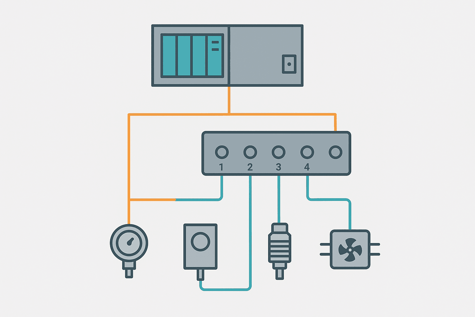
An IO-Link master module typically has 4 or 8 ports. Each port is a dedicated point-to-point link to one device. There is no bus arbitration, no address switches on sensors. The master itself connects upstream to your PLC via a standard fieldbus: PROFINET, EtherNet/IP, Modbus TCP, or EtherCAT depending on the vendor. Popular master families include the IFM AL1xxx series, Balluff BNI00xx, Turck TBEN-S and Siemens ET 200SP IO-Link modules.
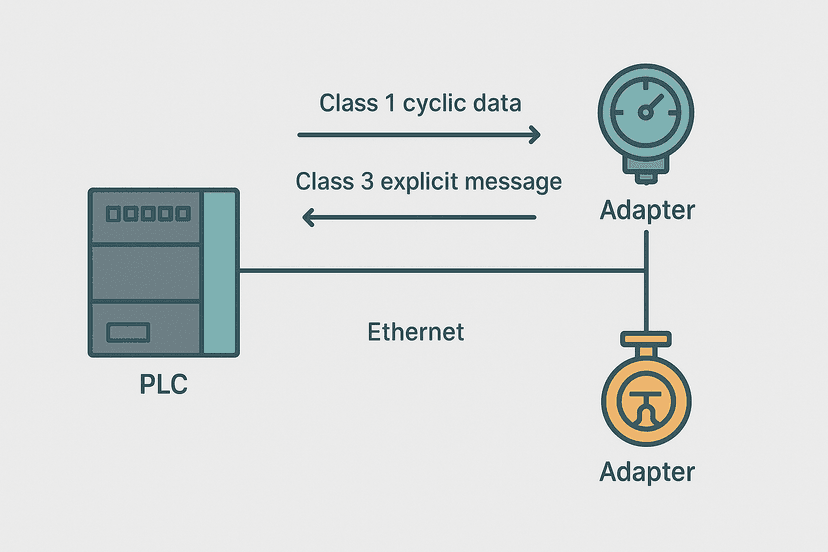
On the PLC side, the master looks like a regular I/O module. The process data from all ports maps into a contiguous block of input and output bytes in the PLC image. If you are on PROFINET IO, the master ships with a GSDML file that you import into TIA Portal or your engineering tool, and the port data slots appear automatically. On EtherNet/IP, you use the EDS file and the master becomes an adapter in your scanner table.
IO-Link Wiring: What Actually Changes from a Standard Sensor
Physically, almost nothing changes. You still use a standard M12 A-coded 4-pin or 5-pin connector. Pin 1 is 24 V supply, pin 3 is 0 V, and pin 4 is C/Q, the combined switching and communication signal. The master port supplies 200 mA per port for the device. For port class B (IO-Link v1.1), pins 2 and 5 add a separate actuator power supply up to 2 A.
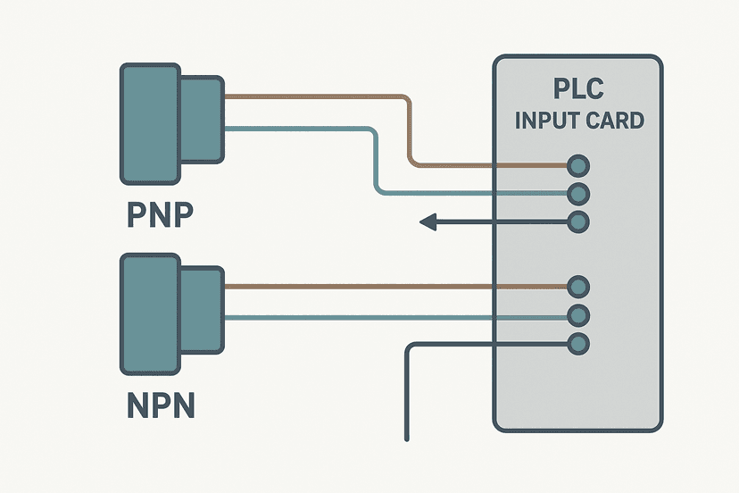
The cable is unshielded, which is a real advantage over shielded analog signal cables. You do not need to worry about shield continuity, ground loops or single-end vs both-end shield termination. Keep the run under 20 m and use a cable rated at least 0.34 mm2 per conductor, and you are done. Compare that to 3-wire PNP/NPN sensor wiring to a conventional PLC input, where the sensor still works but you lose all the smart data.
| Pin | Signal | Notes |
|---|---|---|
| 1 | L+ (24 V DC) | Device supply from master port |
| 3 | L- (0 V) | Common return |
| 4 | C/Q | IO-Link serial data (also switches as SIO in fallback mode) |
| 2 | L+ aux (Class B only) | Separate actuator supply, up to 2 A |
| 5 | L- aux (Class B only) | Return for aux supply |
How IO-Link Process Data Maps to PLC Addresses
This is where engineers sometimes get tripped up the first time. The master maps each port's process data into a byte range in the PLC's I/O image. If you are using a Siemens ET 200SP CM 4xIO-Link, TIA Portal assigns, say, input bytes IB100 to IB131 to the module. Port 1 might occupy IB100 to IB103, port 2 IB104 to IB107, and so on. The exact layout depends on the configured process data length for each device, which you set in the GSDML slot.
Inside the PLC program, you read a pressure sensor value as an INT or DINT from those bytes using a structured type or a MOVE instruction. There is no scaling calculation needed if the sensor outputs calibrated millibar or degrees Celsius directly. If you previously had an analog card for that signal, compare this to the 4-20 mA scaling formula you had to apply every time. IO-Link removes that step entirely for smart devices.
Acyclic parameter access works differently. You send a service request (index and subindex) to the master, the master relays it to the device, and the device responds with the parameter value. In TIA Portal, the RDREC and WRREC instructions handle this. In Studio 5000 with an EtherNet/IP master, you use explicit messaging CIP. It is not hard, but it is an extra step beyond simple I/O reads. Most engineers only do it during commissioning or when changing a setpoint remotely.
IO-Link vs PROFINET and EtherNet/IP: Where Each Fits
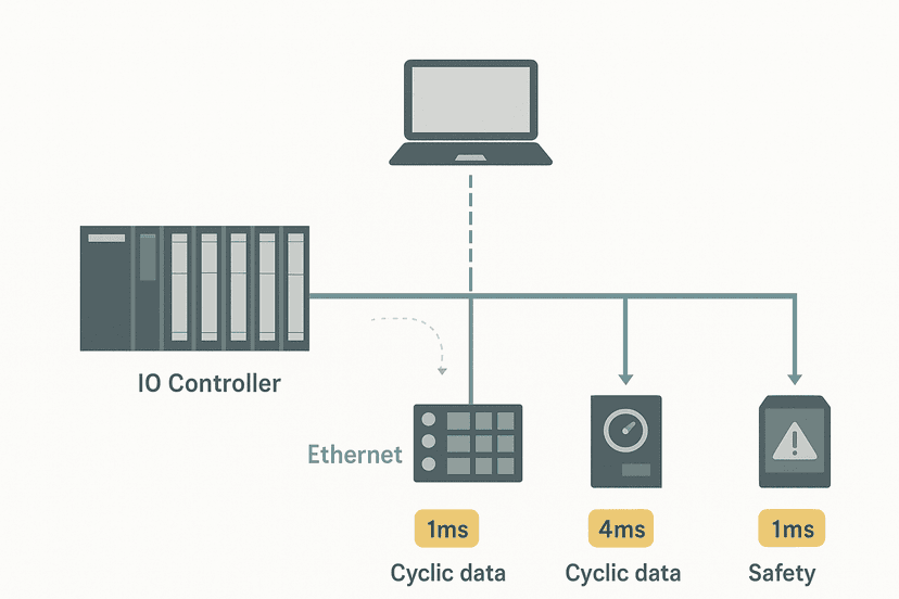
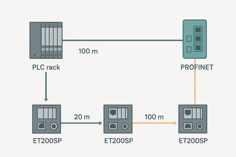
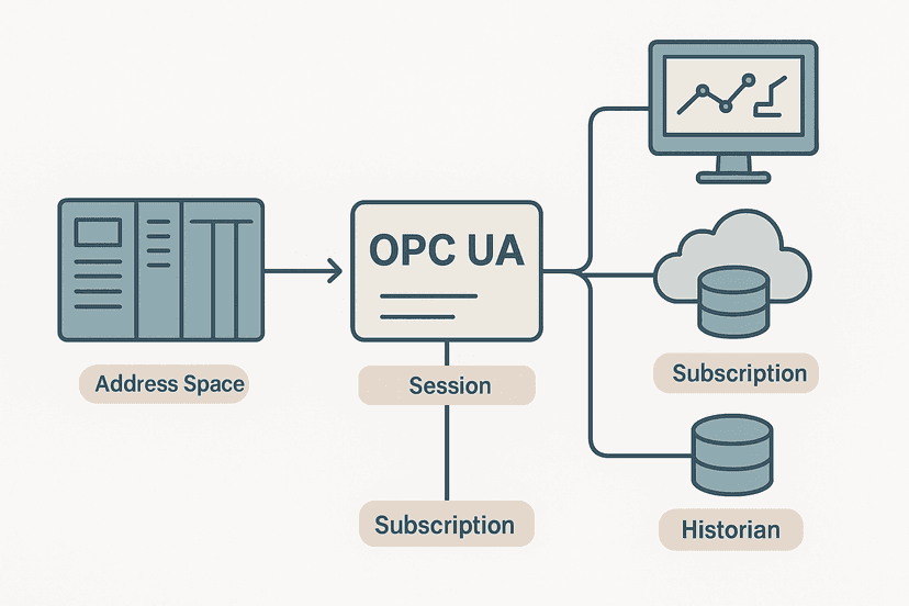
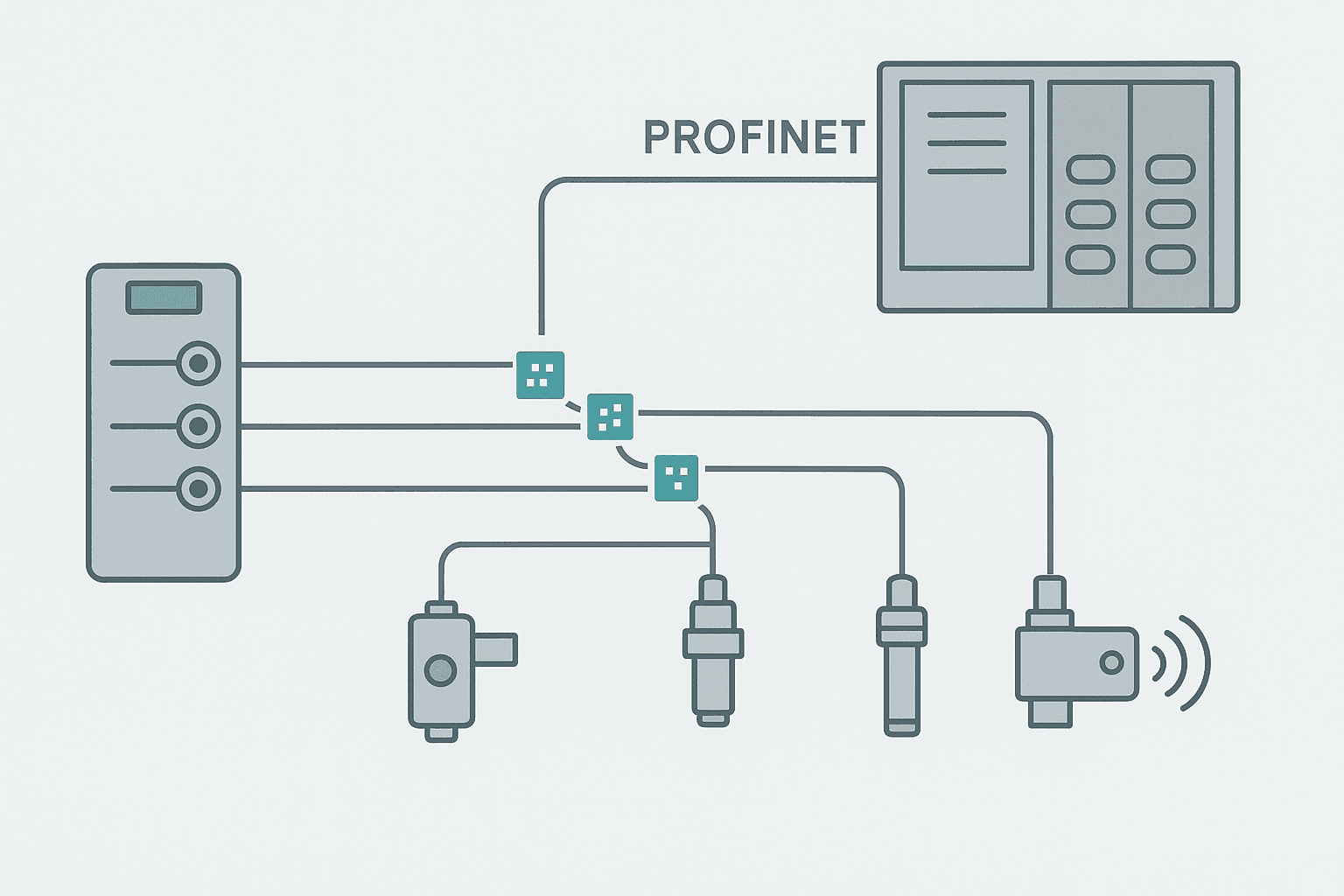
People ask this a lot, and the answer is simple: IO-Link and PROFINET are not competing. IO-Link is the last-meter sensor-level link. PROFINET wiring is the plant-floor fieldbus. They stack on top of each other. An IO-Link master sits at the IO-Link to PROFINET boundary and translates between them. Similarly, IO-Link sits below EtherNet/IP in a Rockwell architecture. If you want to understand where IO-Link fits in the larger communication hierarchy, the OPC UA protocol sits at the top of that stack, pulling data up from the PLC toward MES and cloud systems.
Where IO-Link genuinely beats a plain digital input or a 4-20 mA analog loop: diagnostics. The master can tell your PLC exactly which port has a wire break, which device is reporting an internal fault, and even what temperature the sensor is running at. On a machine with 64 sensors, that kind of specific fault information cuts troubleshooting time dramatically. I commissioned a packaging line where a photoelectric sensor was intermittently misreporting because its housing temperature was creeping over 60 degrees C due to a nearby heat sealer. The IO-Link temperature event flagged it immediately. Without IO-Link, that would have been a classic intermittent sensor fault chase.
IO-Link v1.1 Data Storage: The Swap-Without-Laptop Feature
One feature worth calling out separately is Data Storage, introduced in IO-Link v1.1. When you enable it on a master port, the master reads the device's full parameter set and stores a copy locally. When the sensor is physically replaced, the master detects a new device, compares its device ID, and if it matches, automatically writes the stored parameters back to the replacement unit. The machine is back to spec without a laptop, without an engineer on site, and usually in under 10 seconds. For a high-turnover environment like a food plant where sensors get swapped during hygiene cleans, this is genuinely useful.
Practical IO-Link Commissioning Steps
- Download the IODD file for each device from the manufacturer's site or IODDfinder.io before you start.
- Configure each master port in your engineering tool: set operating mode (IO-Link or SIO digital fallback), process data length, and baud rate (COM3 where supported).
- Wire sensors to master ports using standard M12 cables, max 20 m per port.
- Verify port status LEDs: most masters show green for active IO-Link, amber for SIO digital mode, red for fault.
- In the PLC program, map the process data bytes to named tags. Use the IODD to confirm byte order and scaling factors.
- Test acyclic reads for device identification (index 0x0000 to 0x0002 are standard device info registers across all IO-Link devices).
- Enable Data Storage on ports where sensor swap speed matters.
- Commission diagnostic event handling in the PLC: decide which events generate alarms on your HMI and which are just logged.
On the PLC programming side, IO-Link does not require any exotic instructions. You are reading bytes and words from an I/O image, exactly like any other module. The types of PLC modules article covers how I/O modules in general slot into the PLC rack image, and IO-Link masters follow exactly the same model. The smarts are in the master hardware and the IODD, not in your ladder or structured text.
Where IO-Link Makes Sense and Where It Does Not
IO-Link is worth specifying when you have smart sensors with useful diagnostic or parameter data, when you want to avoid shielded analog cables, or when fast sensor replacement without a laptop matters. It is probably overkill for a simple on/off proximity sensor on a low-criticality position check where you will never change a parameter and the diagnostic value is low. In that case, a standard digital input card connected as described in sinking vs sourcing PLC I/O costs less and is simpler.
The sweet spot: precision measurement sensors (laser distance, pressure, flow), color and contrast sensors with multiple outputs, RFID read/write heads, and any sensor where remote setpoint adjustment during a product changeover saves a technician a ladder climb. On a machine with 20 or more such sensors, an IO-Link master module pays for itself in commissioning time alone.
Keep Learning
Now that you understand how IO-Link sits between the sensor and the fieldbus, the logical next step is understanding how that fieldbus layer above works. If you are on a Siemens architecture, PROFINET IO: Controller, Device and AR Explained covers exactly how the PLC controller side is configured. On a Rockwell system, EtherNet/IP Scanner vs Adapter: How It Works is the equivalent. And if you are still working with conventional analog sensors and want to understand the scaling math you are replacing, 4-20 mA Scaling Formula: The PLC Engineer's Guide has the full breakdown.
Frequently asked questions
What is IO-Link used for?
How fast is IO-Link communication?
Does IO-Link replace PROFINET or EtherNet/IP?
What cable do you use for IO-Link?
What is an IO-Link master module?
Can IO-Link sensors replace 4-20 mA analog inputs?
What is the difference between IO-Link v1.0 and v1.1?
How does IO-Link parameter storage work?
Is IO-Link the same as IQ-Sense?
What diagnostic information does IO-Link provide?
Learn this by building it
There is a PLC in this site. It runs a real scan engine, checks your logic against the same tests a working machine would fail, and needs no download and no account.
Open the exercisesFree, no signup, runs in your browser. See all 16 exercises.
Was this helpful?