One-Shot Rising Edge in Ladder Logic: OSR Explained
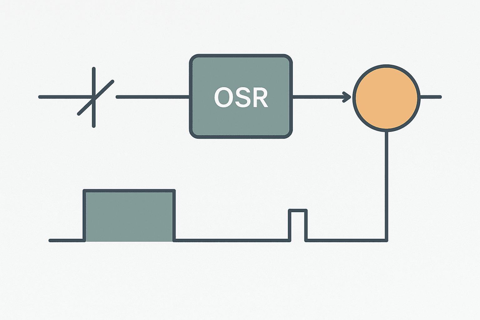
The one-shot rising instruction is one of those things that looks trivial until you skip it and spend an afternoon wondering why your counter is reading 4,000 when the operator only pressed the button twice. Every working PLC programmer has that story. The OSR instruction solves a specific, concrete problem: turning a sustained TRUE signal into a single-scan pulse so downstream logic runs exactly once per trigger event.
What Is a One-Shot Rising Edge Instruction in Ladder Logic?
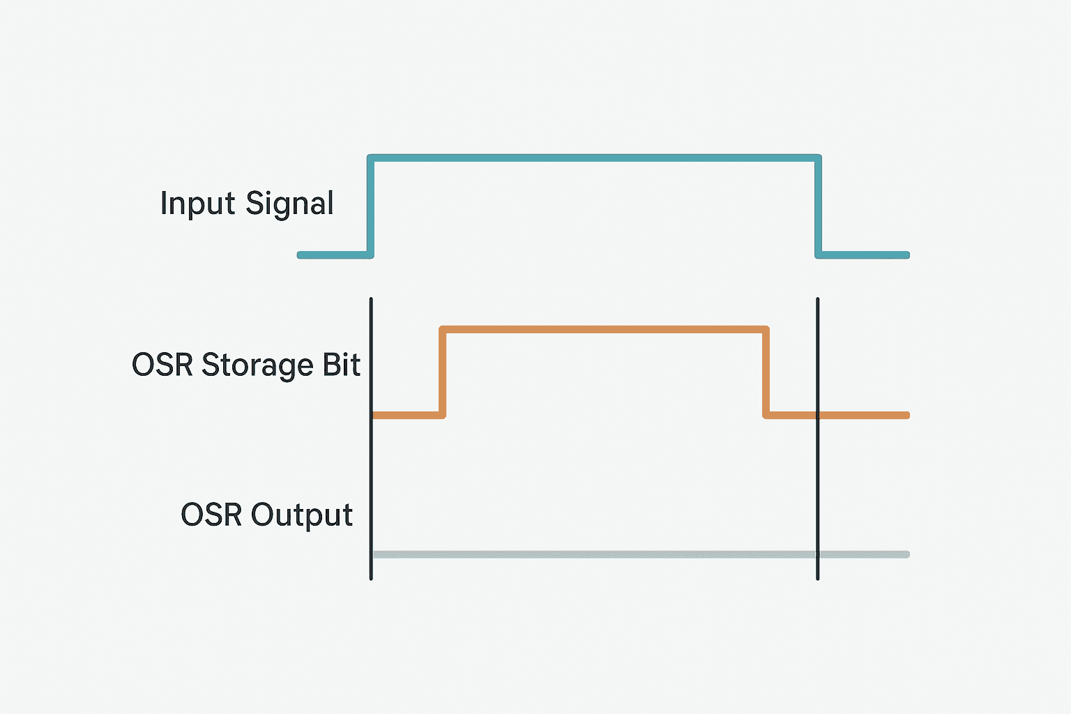
A one-shot rising (OSR) instruction monitors its rung condition and produces a TRUE output for exactly one PLC scan the moment that condition transitions from FALSE to TRUE. On every subsequent scan while the condition stays TRUE, the output is FALSE. The output returns to FALSE immediately on the scan after the trigger, regardless of how long the input stays high. This converts any sustained signal into a single-scan pulse that downstream instructions can act on without repeating.
Why You Need It: The Scan Cycle Problem
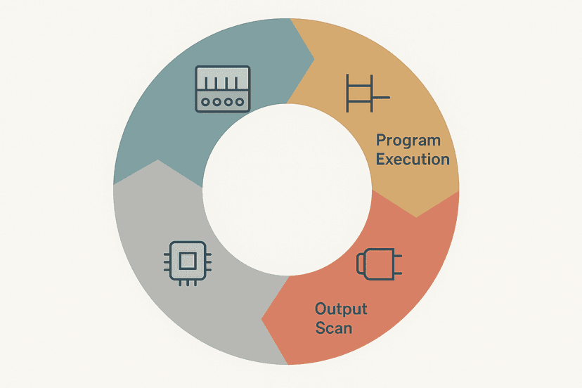
To understand why OSR exists, you need to remember how the PLC scan cycle works. The CPU evaluates every rung, every scan, typically at 1 to 20 ms intervals. If you wire a pushbutton directly to a CTU counter contact, and the operator holds the button for 500 ms, the counter will increment on every scan during that 500 ms. At a 10 ms scan time that is 50 counts from one button press.
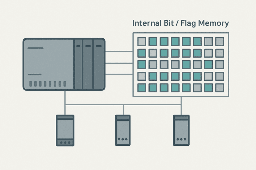
The same problem hits recipe loads, alarm latches, valve toggles, and any logic that should fire once per event. A one-shot is the right fix. It is not a workaround, it is the designed solution. Understanding this also explains why PLC internal bits and flags matter so much: the OSR needs a dedicated bit to store its previous state, and that bit has to live somewhere reliable.
The Storage Bit: What It Does and Why It Must Be Unique
Every OSR instruction requires a storage bit. This is an internal memory bit that the instruction writes to each scan. The OSR logic is simple:
- If rung is TRUE and storage bit is FALSE: fire the output TRUE, set storage bit TRUE.
- If rung is TRUE and storage bit is TRUE: output stays FALSE (already fired).
- If rung is FALSE: output is FALSE, clear storage bit FALSE so the next rising edge can fire again.
The gotcha that catches every newcomer: you must assign a unique storage bit to every OSR in the program. If two OSR instructions share the same bit, the second one reads a bit already set by the first and never fires. In Studio 5000 you would use unique BOOL tags, for example OSR_RecipeLoad_Storage and OSR_FaultDetect_Storage. Never use a generic OSR_Bit1 and then reuse it three rungs down.
OSR vs ONS in Studio 5000 Logix
Rockwell Allen-Bradley gives you two options in Studio 5000. OSR (One-Shot Rising) is a coil-style output instruction. You place it on the right side of the rung, and it passes the one-shot pulse to the bit you assign. ONS (One-Shot) is a contact-style instruction placed inline in the rung condition. The rung power flows through ONS for one scan on a rising edge, then blocks. Both do the same job.
| Instruction | Placement | Style | Best for |
|---|---|---|---|
| OSR | Right side of rung (output) | Coil | Writing a one-shot bit used by multiple downstream rungs |
| ONS | Inline in rung condition (contact) | Contact | Single-rung edge detection, cleaner to read inline |
| OSF | Right side of rung (output) | Coil | Detecting falling edge (TRUE to FALSE transition) |
In practice, most experienced Logix programmers prefer ONS for inline use because it reads naturally left to right. OSR is useful when you want to generate a one-shot bit that several rungs below can all XIC on. Both are legitimate. Just do not mix up the storage bit assignment.
One-Shot Rising Edge in Siemens TIA Portal
Siemens handles edge detection differently. In TIA Portal ladder, you use a P contact (positive edge detection contact) directly in the rung. It behaves like a contact that passes power for one scan on a rising edge. There is also the P_TRIG function block if you need the edge detection result as a bit you can reference elsewhere. The P contact approach is the most compact and is what you will see in most S7-1200 programs in TIA Portal.
One difference from Logix: the Siemens P contact stores its state internally within the block's instance data, so you do not manually assign a storage bit. This removes the duplicate-bit problem but also means you cannot easily inspect the storage state from outside the rung. For S7-1200 timers and counters that need edge-triggered inputs, the P contact is the go-to.
One-Shot Rising Edge Ladder Logic Example: Counter Increment
Here is a real-world example: a proximity sensor on a conveyor counts products passing a gate. The sensor output stays TRUE for roughly 200 ms per part. Without a one-shot, a CTU counter driven directly by the sensor XIC contact would increment every scan during those 200 ms. At a 5 ms scan time that is 40 false counts per part. With an OSR or ONS, you get exactly one count per part.
Product Counter with ONS Rising-Edge Debounce (Studio 5000). Ladder logic (3 rungs): Rung 0: examine if ProxSensor_Part is on (XIC), then examine if Prox_EdgeStorage is on (XIC), then CTU on Part_Counter. Rung 1: examine if Part_Counter.DN is on (XIC), then examine if Batch_Done_OS is on (XIC), then latch output Batch_Done_Latch (OTL). Rung 2: examine if Batch_Done_Latch is on (XIC), then examine if HMI_BatchReset is on (XIC), then unlatch output Batch_Done_Latch (OTU), then either RES on Part_Counter. Rung 1: The proximity sensor contact passes through an ONS instruction (storage bit: Prox_EdgeStorage) so CTU only increments once per part, regardless of how long the sensor stays TRUE. Rung 2: When the counter reaches its preset (DN bit), an OSR fires once to set Batch_Done_Latch using OTL. The OSR storage bit (Batch_Done_Storage) prevents the latch from being re-set on every scan while DN stays TRUE. Rung 3: The operator resets the batch by acknowledging at the HMI, which resets both the latch and the counter.
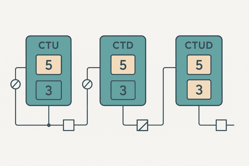
Notice the two distinct storage bits: Prox_EdgeStorage for the ONS on rung 1, and Batch_Done_Storage for the OSR on rung 2. They are different bits doing different jobs. This is a pattern you will use constantly. For a deeper look at CTU and CTD instructions, see PLC Counter Instructions: CTU, CTD and CTUD Explained.
Common Use Cases for One-Shot Instructions
- Counter increments from sensors or pushbuttons (the classic case above).
- Triggering a fault latch via OTL on the rising edge of a fault bit, so the latch fires once and holds. See OTL and OTU Latch Coils in Ladder Logic Explained for how latch coils pair with one-shots.
- Loading a recipe or preset value into a working register when an HMI button is pressed.
- Toggling an output state: XOR the current state with a one-shot pulse to flip it.
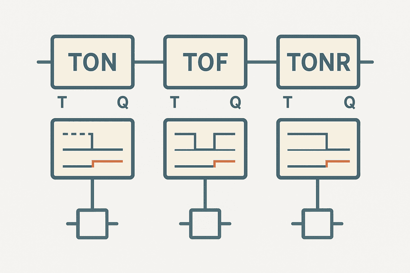
- Initiating a timed sequence: the one-shot sets a bit that enables a TON timer on the next rung. Mixing edge detection with timers is covered in TON, TOF and TONR Timers: What Actually Differs.
- Alarm acknowledgement: detect the rising edge of an HMI ACK button to clear a latched fault without the clear logic running every scan.
Troubleshooting One-Shot Logic That Is Not Firing
When a one-shot seems stuck or never fires, work through these checks:
- Go online and watch the storage bit. If it is permanently TRUE, the rung condition never went FALSE, so the OSR can never see a new rising edge. Find out why the rung condition is stuck. PLC Troubleshooting with Online Monitoring covers exactly this technique.
- Check for duplicate storage bits. Search your project for the storage bit tag name and confirm it appears only once as an OSR or ONS operand.
- Check the rung condition, not just the OSR. If the XIC contacts feeding the OSR are not all energized simultaneously for at least one scan, the one-shot never fires. Use online monitoring to check each contact state individually.
- Verify scan time vs signal duration. If the input signal is shorter than one scan cycle, the PLC may miss it entirely. A 2 ms pulse on a 10 ms scan will be missed roughly 80% of the time. For short pulses you need hardware input filtering disabled and possibly a faster task. See PLC Scan Cycle Problems: Logic and Timing Faults for scan-time edge cases.
- Check for a forced state. A forced TRUE on the storage bit prevents the rising-edge detection from seeing any new transition.
One-Shot vs Latch Coil: Choosing the Right Tool
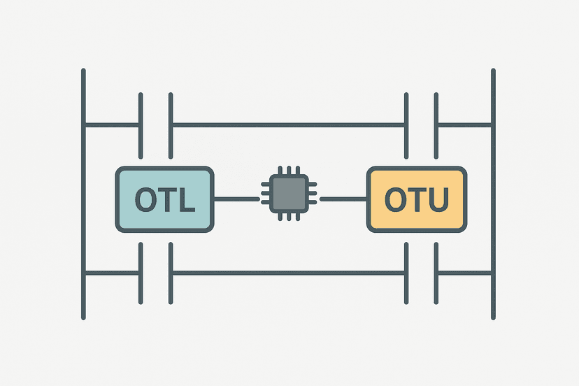
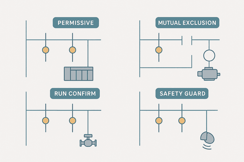
A one-shot and an OTL latch coil are often used together, but they are not interchangeable. The one-shot produces a single-scan pulse. The OTL latch coil holds a bit TRUE until explicitly cleared with OTU. The typical pattern is: OSR detects the event edge, OTL captures the result into a held state, and OTU clears it when the operator acknowledges. If you drive an OTL directly from a sustained contact, it will keep setting every scan but will still hold after the contact goes FALSE, so functionally it works. But driving OTL from an OSR is cleaner and avoids any ambiguity about when the latch was set. Check Ladder Logic Interlocks: How They Work and Why for how latches and interlocks combine in real sequences.
Also worth knowing: in Studio 5000 you can use XIC and XIO contacts on the output bit of the OSR to feed multiple downstream rungs from a single one-shot event. One OSR sets a BOOL tag, and three rungs below each XIC on that tag. All three fire for that one scan. This is cleaner than putting three separate OSR instructions on three separate rungs, and it avoids the storage-bit duplication trap.
Falling Edge Detection: OSF and N Contacts
Everything above applies equally to falling-edge detection. Studio 5000 OSF (One-Shot Falling) fires for one scan when the rung condition transitions from TRUE to FALSE. Siemens uses an N contact in TIA Portal ladder. Falling-edge one-shots are useful for detecting the end of a cycle, the moment a part leaves a sensor, or when a VFD run-confirm drops. The storage bit rules are identical: unique bit per instruction, never shared.
What to Read Next
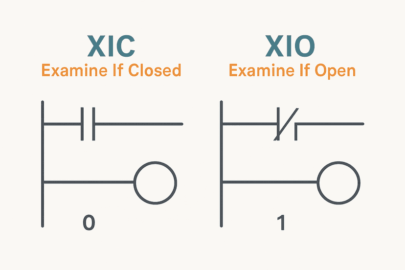
One-shot instructions make the most sense once you understand the broader context of how contacts, coils, and internal bits work together. Start with XIC vs XIO: Ladder Logic Contacts Explained if contacts still feel fuzzy, then move to OTL and OTU Latch Coils in Ladder Logic Explained to see how one-shots and latches combine. For a full practical project that uses edge detection inside a sequence, the PLC Bottle Filling Machine: Step-by-Step Project is a good next challenge.
Frequently asked questions
What does OSR mean in PLC ladder logic?
What is the storage bit in an OSR instruction?
Can I use the same storage bit for two OSR instructions?
What is the difference between OSR and ONS in Studio 5000?
When should I use a one-shot instead of a normal contact?
Does a one-shot work the same way in Siemens TIA Portal?
What happens if the OSR storage bit is forced ON accidentally?
Can I use a one-shot on a falling edge?
Will an OSR fire correctly if the triggering condition lasts only one scan?
Now build it
You have just read about ONS and CTU and CTD. Reading a rung and making one behave are different skills, and the second one is the job.
Batch Counter (CTU + RES)
Intermediateabout 15 minCount parts passing a sensor; after 4 parts the batch is done and a lamp turns on. A reset button starts the next batch. Counters count RUNG EDGES: a part sitting on the sensor counts once, not forever.
Build this rungFree, no signup, runs in your browser. See all 16 exercises.
Was this helpful?