Falling-Edge One-Shot in Ladder Logic: OSF Explained
Most PLC engineers learn the rising-edge one-shot, OSR, early on. But the falling-edge version, OSF, gets far less attention, and that gap causes real bugs. If you have ever seen a counter increment twice, an alarm latch at the wrong moment, or a valve fire when a sensor clears instead of when it triggers, a missing OSF was probably the culprit.
What Is a Falling-Edge One-Shot (OSF) in Ladder Logic?
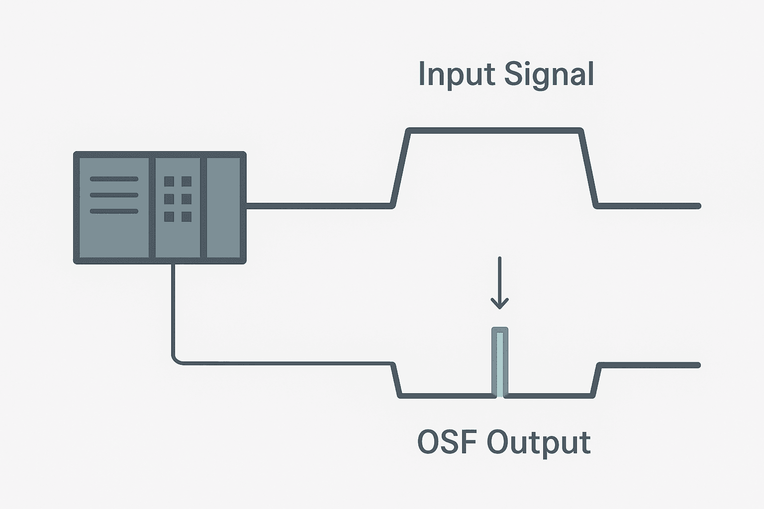
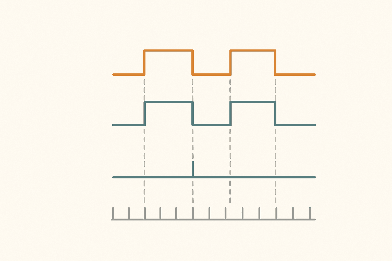
The OSF instruction (One Shot Falling) produces a single TRUE output for exactly one PLC scan cycle at the moment its rung input transitions from TRUE to FALSE. It uses a dedicated BOOL storage bit to remember the previous state of the rung. Every subsequent scan, as long as the input stays FALSE, the OSF output remains FALSE. The output only pulses again if the input goes TRUE again and then drops back to FALSE.
OSF vs OSR: Picking the Right Edge
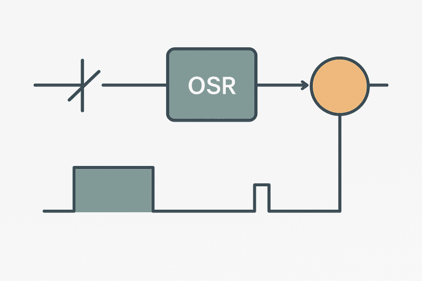
The one-shot rising edge (OSR) instruction fires when a signal turns ON. OSF fires when it turns OFF. That single difference determines everything about which one you need.
| Instruction | Fires on | Typical use case |
|---|---|---|
| OSR | FALSE to TRUE transition | Start command pressed, sensor detects part arriving |
| OSF | TRUE to FALSE transition | Sensor clears, button released, valve de-energizes |
| ONS (Logix) | Rising edge, no output bit | Simpler rising-edge in newer Logix versions |
A common question is whether you can just invert the signal and use OSR instead. You can, but it adds an extra internal bit and an extra rung, and it is easy to forget why the inversion is there six months later. OSF is self-documenting: the name tells the next engineer exactly what you are detecting.
The Storage Bit: The Detail That Catches Everyone
Both OSR and OSF require a dedicated BOOL tag as the second parameter. The instruction writes to this bit every scan to record whether the rung was TRUE or FALSE last time. On the next scan it compares the current state to the stored state and fires its output bit if they differ in the right direction.
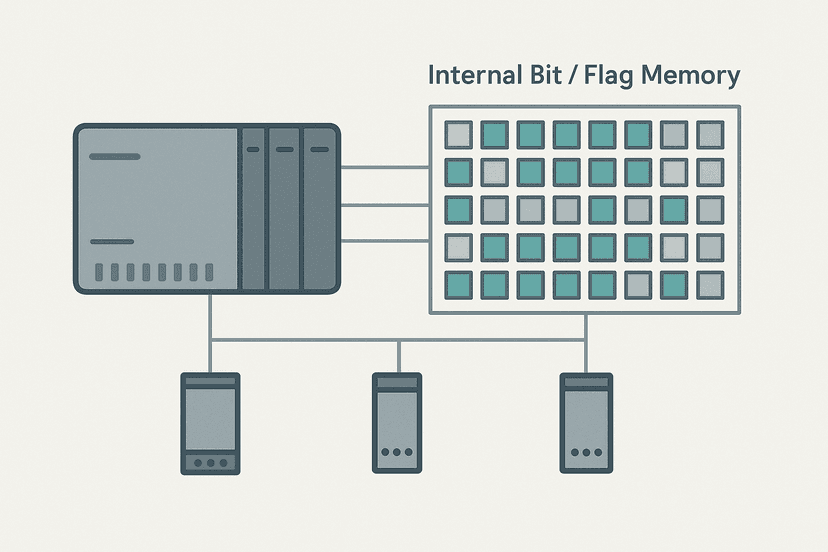
Tag naming convention matters here. A pattern like ProxSensor_OSF_Store or Valve_FE_Bit makes it obvious the bit belongs to an edge-detection instruction and should never be touched by anything else. This is part of the same discipline you need when working with PLC internal bits and flags.
How OSF Behaves Across the Scan Cycle
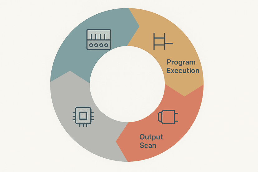
Understanding how the PLC scan cycle works is essential for edge detection. The PLC reads all physical inputs once at the start of the scan, executes logic, then writes outputs. OSF compares the current input image to the stored bit. If the input image was TRUE last scan and is FALSE this scan, the OSF output coil turns TRUE for this one scan only.
One implication: if a physical input bounces faster than one scan, OSF may miss the edge or fire multiple times. For noisy proximity sensors, add a short TON debounce timer before the OSF rung. The intermittent sensor fault guide covers why sensor noise causes exactly this kind of problem.
Falling-Edge One-Shot in Studio 5000: Syntax and Tags
In Studio 5000 the OSF instruction sits in the Bit instruction group. It takes two parameters: the output bit (what turns on for one scan) and the storage bit (the dedicated BOOL memory). Both must be BOOL tags. The rung condition, what sits to the left of OSF, is the signal you are monitoring.
// Rung syntax in Studio 5000 (Logix5000)
// OSF(Output_Bit, Storage_Bit)
//
// Example: detect when the infeed sensor clears
// Tags:
//   Infeed_ProxSensor  : BOOL  (from I/O image)
//   Infeed_Prox_OSF_Out : BOOL  (one-shot output, used by downstream rungs)
//   Infeed_Prox_OSF_Str : BOOL  (storage, used ONLY by this OSF)

XIC(Infeed_ProxSensor)OSF(Infeed_Prox_OSF_Out, Infeed_Prox_OSF_Str)
The output bit Infeed_Prox_OSF_Out is TRUE for one scan only. Any rung that needs to react to the falling edge should reference this bit. Because XIC and XIO contacts evaluate in the same scan, downstream rungs using XIC on Infeed_Prox_OSF_Out will see it as TRUE in the same scan it fires.
Worked Example: Part-Exit Counter on a Conveyor Zone
Here is a real scenario I have used more than once. A diffuse proximity sensor sits at the exit of a conveyor accumulation zone. The sensor reads TRUE while a part is present. When the part exits, the sensor drops to FALSE. You want to count each part that leaves the zone, not the parts that arrive.
If you used an OSR on the sensor, you would count arrivals. If you used a plain CTU with an XIC on the sensor, the counter would increment every scan while the part is present, easily hitting thousands. OSF is the right tool: one pulse per departure, one count increment.
Zone Exit Counter Using OSF (Studio 5000). Ladder logic (4 rungs): Rung 0: examine if Zone_ExitSensor is on (XIC), then examine if Zone_Exit_OSF_Out is on (XIC). Rung 1: examine if Zone_Exit_OSF_Out is on (XIC), then examine if ZoneExit_FaultLatch is off (XIO), then CTU on ZoneExit_PartCount. Rung 2: examine if ZoneExit_PartCount.DN is on (XIC), then examine if Batch_Complete_OSF is on (XIC), then latch output Batch_Complete_Latch (OTL). Rung 3: examine if Batch_Complete_Latch is on (XIC), then examine if HMI_BatchReset is on (XIC), then unlatch output Batch_Complete_Latch (OTU), then either RES on ZoneExit_PartCount. Rung 1: OSF detects the falling edge of the zone exit sensor (part leaving). Rung 2: The one-shot output increments a CTU counter, but only if no fault is latched. Rung 3: When the counter reaches 9999, an OSR latches the batch complete alarm for exactly one scan. Rung 4: The operator acknowledges and resets the counter. The OSF storage bit Zone_Exit_OSF_Str is used exclusively by this instruction.
OSF in Other PLC Platforms
Studio 5000 is not the only place you will find falling-edge detection. The concept is universal across IEC 61131-3 platforms. In Siemens TIA Portal the equivalent is the F_TRIG function block (Falling TRIGger), which you can use in both ladder and Structured Text. You can see how Siemens handles similar logic in the TIA Portal Structured Text guide.
In CODESYS and Omron Sysmac Studio you also get F_TRIG as a standard IEC function block. Mitsubishi GX Works3 uses the PLF (Pulse Falling) instruction in ladder, which has no separate storage bit because the CPU handles that internally. The GX Works3 getting-started guide covers PLF in more detail.
| Platform | Falling-edge instruction | Storage bit required? |
|---|---|---|
| Studio 5000 / Logix5000 | OSF | Yes, dedicated BOOL tag |
| TIA Portal (S7-1200/1500) | F_TRIG FB | Internal to FB instance |
| CODESYS / Omron Sysmac | F_TRIG FB | Internal to FB instance |
| Mitsubishi GX Works3 | PLF | No, CPU-managed |
| Omron CX-Programmer | DIFD | No, CPU-managed |
Common Mistakes and How to Avoid Them
- Shared storage bits: copy-paste a rung and forget to rename the OSF storage tag. Both instructions fight over the same bit and produce random pulses. Always give every OSF its own storage BOOL.
- OSF on a coil output instead of a sensor: OSF fires on the falling edge of whatever drives it. If you put OSF after an OTE coil that is also controlled by other rungs, the edge may fire unexpectedly when the coil drops for unrelated reasons.
- Expecting OSF to hold its output: OSF is TRUE for exactly one scan. If you need the result to persist, feed the OSF output into an OTL latch coil, as shown in the counter example above.
- Forgetting initialization on first scan: on power-up the storage bit is FALSE. If the sensor happens to be TRUE at startup and then drops to FALSE before the first scan completes, OSF may or may not fire depending on the order rungs execute. For safety-related counters, initialize the storage bit explicitly in a first-scan rung.
- Using OSF inside a called subroutine that runs multiple times per scan: if the subroutine is called in a loop, the storage bit is updated each call, corrupting the edge detection. Keep edge instructions in main routines or routines called once per scan.
When OSF Saves You From a Logic Problem
A scenario where OSF prevents a real bug: alarm latching on a PLC output going off. Say you have a valve output that de-energizes due to a fault. You want to latch an alarm the moment the valve drops, not continuously while it stays low. Without OSF you would need a memory bit, an XIO rung and careful ordering. With OSF you get it in one rung:
XIC(Valve_Out)OSF(Valve_Off_OS, Valve_Off_Store) followed by XIC(Valve_Off_OS)XIC(Sys_Running)OTL(Valve_Off_Alarm). The alarm latches once when the valve drops while the system is supposed to be running. It does not latch on a commanded stop. This is the kind of ladder logic interlock pattern that separates tidy programs from messy ones.
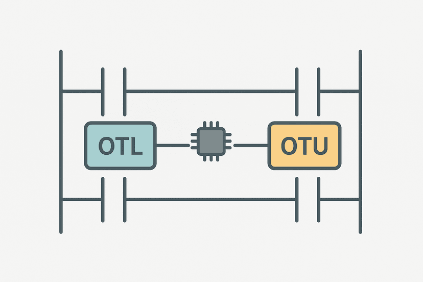
You can combine OSF with OTL and OTU latch coils to build self-clearing alarms that require operator acknowledgement, exactly as shown in the counter example. The one-scan pulse from OSF is the trigger; the latch holds it until the operator acts.
For troubleshooting these kinds of latched conditions, PLC online monitoring is invaluable. A one-scan pulse from OSF is too fast to see visually, but you can watch the latch bit it drives, or force the storage bit to test the edge behavior without actually cycling the physical signal.
OSF and the Wider Edge-Detection Picture
Edge detection in ladder logic, whether rising or falling, is one of the fundamental building blocks of PLC programs. Once you are comfortable with OSR and OSF you will find them everywhere: debouncing sensors, triggering counters (see the CTU, CTD and CTUD counter guide), starting timers on a transition rather than a level, and feeding timer instructions that need a clean single trigger.
If you are preparing for a technical interview, edge detection questions come up often. The ladder logic interview questions post includes several OSR and OSF scenarios that interviewers actually ask. Understanding the storage bit requirement and the one-scan behavior is what separates a solid answer from a vague one.
What to Read Next
If you want to see rising and falling edge detection working together in a complete program, the PLC bottle filling machine project uses both to manage fill start and stop events cleanly. For a deeper look at how memory and addressing support these patterns, PLC memory and addressing explained fills in the background. And if you are still building your ladder fundamentals, XIC vs XIO contacts explained is the right place to start before adding edge-detection instructions on top.
Frequently asked questions
What does the OSF instruction do in Studio 5000?
What is the difference between OSR and OSF?
Can I use OSF on a physical input bit directly?
What happens if OSF fires during a fault or program mode change?
Is there an equivalent to OSF in Siemens TIA Portal?
Can OSF be used inside a For loop or a subroutine called multiple times?
How do I detect both rising and falling edges on the same signal?
What is a practical example where OSF is better than OSR?
Now build it
You have just read about OSF and ONS. Reading a rung and making one behave are different skills, and the second one is the job.
One Button Toggle (edge contacts)
Advancedabout 20 minOne push button: press → lamp ON, press again → lamp OFF. Sounds trivial, defeats most beginners. The trick is a rising-edge contact plus a snapshot of the lamp's state taken BEFORE you change it.
Build this rungFree, no signup, runs in your browser. See all 16 exercises.
Was this helpful?