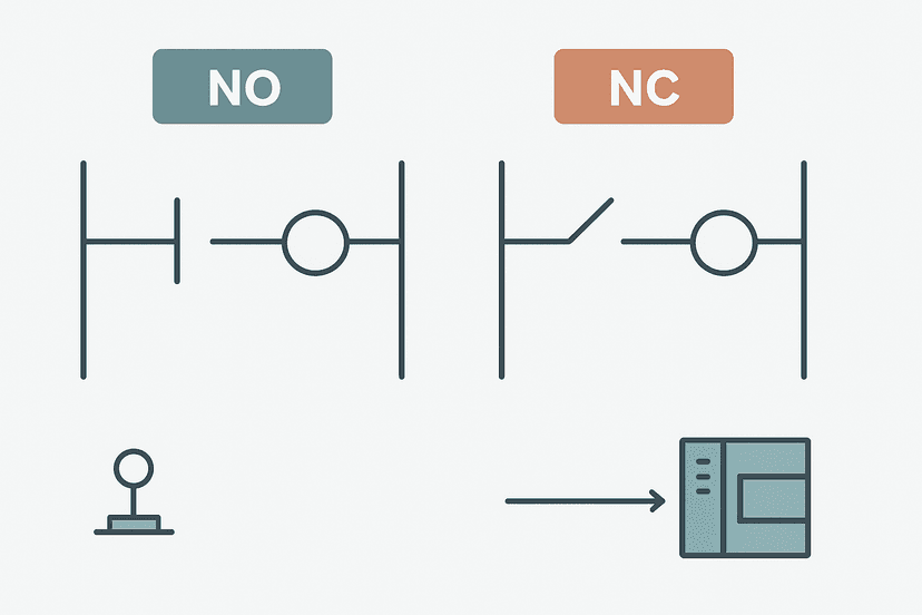
Set-Reset Flip-Flop in Ladder Logic: Full Guide
The set-reset flip-flop is one of the oldest patterns in relay logic and it is still one of the most useful things you can build in a PLC program. If you have ever needed a fault latch, a mode-select bit, or a step-state flag that holds its value independently of the conditions that set it, this is the pattern you reach for. And yet it is consistently misunderstood, misapplied, and occasionally written in ways that produce race conditions that are genuinely painful to debug on a live machine.
What Is a Set-Reset Flip-Flop in Ladder Logic?
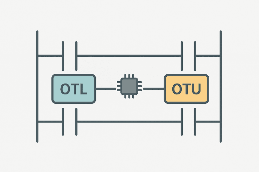
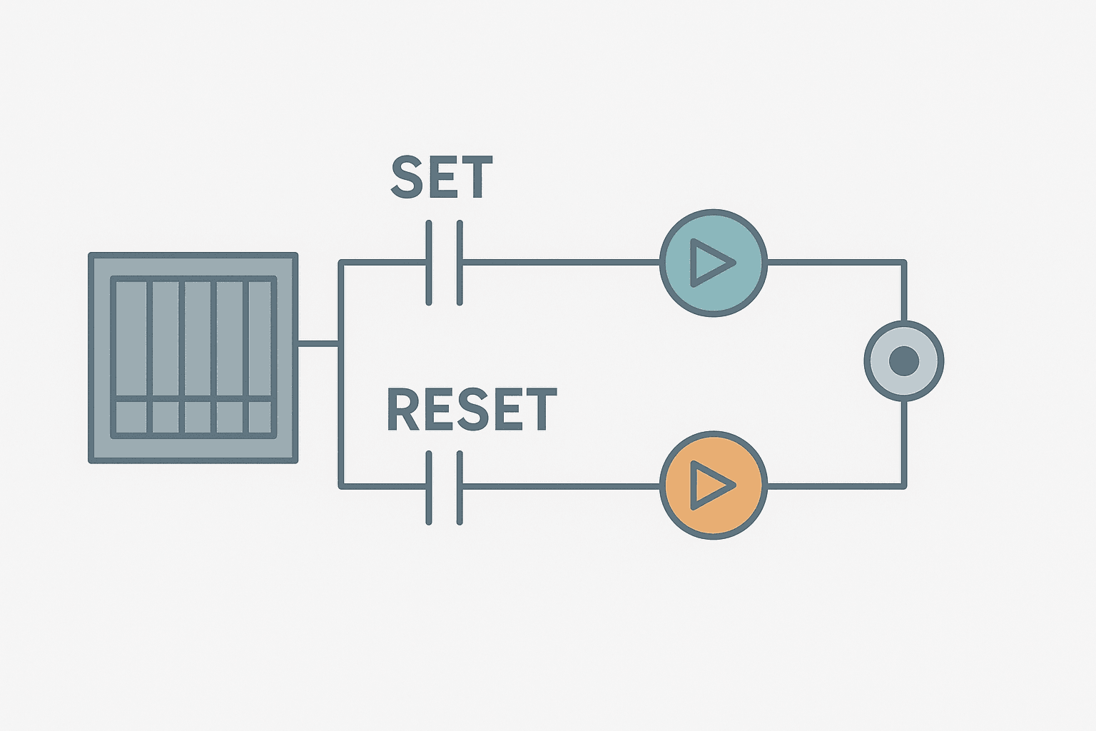
A set-reset flip-flop in ladder logic is a memory element controlled by two separate rungs: a Set rung that latches a BOOL tag to TRUE, and a Reset rung that unlatches it back to FALSE. Once the Set rung fires, the bit stays TRUE even after the Set condition goes away. It only returns to FALSE when the Reset rung fires. The bit holds its last commanded state between every PLC scan, which is exactly the behavior you need when your ON condition and your OFF condition are separate, asynchronous events.
SR Flip-Flop vs Seal-In Rung: Which One Do You Need?
A seal-in rung wires a normally open contact of the output coil in parallel with the Start button. The coil holds itself ON as long as the Stop contact stays closed. It is tidy, self-contained, and easy to read. But it has a structural limitation: the ON and OFF conditions must both live on the same rung. The moment you need to set the bit from one rung and clear it from three different rungs spread across your program, the seal-in approach gets messy fast.
The SR flip-flop solves that by separating Set and Reset into independent rungs. Each rung can have its own logic, its own interlocks, its own timing. That is why fault latches almost always use OTL and OTU: the fault sets the latch from a sensor condition, and the reset requires an operator acknowledge from an HMI button on a completely different rung. You could not do that cleanly with a seal-in. See the OTL and OTU coil breakdown if you want a deeper look at the instruction-level behavior.
| Feature | Seal-In Rung | SR Flip-Flop (OTL/OTU) |
|---|---|---|
| Set condition location | Same rung as output | Dedicated Set rung, anywhere in program |
| Reset condition location | Same rung as output | Dedicated Reset rung, anywhere in program |
| Multiple reset conditions | Awkward, all in series on one rung | Each reset gets its own rung naturally |
| Instruction used | OTE with parallel self-contact | OTL for Set, OTU for Reset |
| State retention on power loss | Lost (unless tag is retentive) | Lost (unless tag is retentive) |
| Race condition risk | Low, one rung wins | Yes, scan order determines priority |
How Scan Order Creates Set-Dominant or Reset-Dominant Behavior
This is the gotcha that gets people. The PLC scans rungs top to bottom on every cycle. If both your Set rung and your Reset rung are true at the same instant, the one that is lower in the program wins because it executes last and overwrites what the earlier rung wrote. That makes your flip-flop either Set-dominant or Reset-dominant depending purely on rung order.
Siemens TIA Portal makes this explicit with two separate function blocks: the SR block (Set-dominant) and the RS block (Reset-dominant). In Studio 5000 there is no dedicated block, so you decide by controlling which rung is last. Put your Reset rung below your Set rung for Reset-dominant behavior. Put your Set rung below your Reset rung for Set-dominant. Document it in a comment. This is not optional. Someone will be staring at this code at midnight six months from now and they need to know the intent.
Practical SR Flip-Flop: Agitator Mode Select with Fault Guard
Here is a real-world example I built on a chemical dosing skid. The agitator had two modes: Slow and Fast. The operator could switch modes from the HMI, but the fast mode had to be locked out if a vibration fault was active. A seal-in rung would have required a complex single rung. The SR pattern made it readable and maintainable.
Agitator Mode SR Flip-Flop with Vibration Fault Guard (Studio 5000). Ladder logic (7 rungs): Rung 0: examine if HMI_FastMode_Cmd is on (XIC), then examine if Agitator_VibFaultLatch is off (XIO), then examine if Agitator_FastMode is off (XIO), then latch output Agitator_FastMode (OTL). Rung 1: examine if HMI_SlowMode_Cmd is on (XIC), then unlatch output Agitator_FastMode (OTU). Rung 2: examine if Agitator_VibFaultLatch is on (XIC), then unlatch output Agitator_FastMode (OTU). Rung 3: examine if Agitator_FastMode is on (XIC), then energize output Agitator_Fast_Out (OTE). Rung 4: examine if Agitator_FastMode is off (XIO), then examine if Agitator_SlowMode_Cmd is on (XIC), then energize output Agitator_Slow_Out (OTE). Rung 5: examine if Agitator_Vib_Sensor is on (XIC), then examine if Vib_Fault_OS is on (XIC), then latch output Agitator_VibFaultLatch (OTL). Rung 6: examine if Agitator_VibFaultLatch is on (XIC), then examine if HMI_VibFaultAck is on (XIC), then examine if Agitator_Vib_Sensor is off (XIO), then unlatch output Agitator_VibFaultLatch (OTU). Rung 1: Sets FastMode latch only if the HMI requests it, no vibration fault is active, and it is not already set (prevents re-triggering). Rungs 2 and 3: Two independent reset conditions (operator slow command, or fault active) both clear FastMode. Rungs 4 and 5: Output coils driven from the mode bit. Rungs 6 and 7: Vibration fault latch using OSR and OTL, cleared by operator acknowledge when sensor has cleared. Reset-dominant: the Reset rungs (2 and 3) are below the Set rung (1).
The diagram above evaluates one scan. Run these exact rungs on a real scan cycle to watch the latching and the timers behave.
Run this in the simulatorState Retention: Does the Latch Survive a Power Cycle?
Short answer: not by default. In Studio 5000 a standard BOOL tag is backed by SRAM that clears on power loss. If you need the latch to survive a power cycle, mark the tag as Retain in the tag properties. The controller then copies it to non-volatile storage (the same way it handles other retentive data). On a Siemens S7-1200 or S7-1500, you need to place the BOOL in a Data Block with the Retain attribute set, or use the retentive M-area configured in the CPU properties. The S7-1200 data blocks article covers that in detail.
Think carefully about what retaining a fault latch actually means. If a high-temperature fault latch retains across a power cycle, the machine will come up in a faulted state after any outage and require an operator acknowledge before it can run. That is usually exactly what you want for safety. But a mode-select bit that retains might put the machine in an unexpected mode on restart. Design intent matters here.
Common Mistakes and How to Avoid Them
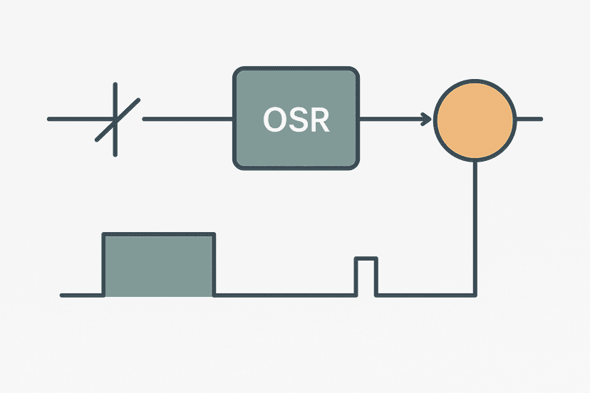
- Forgetting to guard the Set rung against re-triggering. If your Set rung has no XIO contact checking the bit itself, every scan where the Set condition is true will re-execute OTL. That is harmless with OTL (it is idempotent) but it makes OSR-based one-shot patterns on the same bit unreliable. Add an XIO of the latch bit in series with the Set condition if you need edge behavior.
- Undefined priority when both Set and Reset are true. This happens more than you think on startup when initialization rungs and process rungs execute together. Decide on Set-dominant or Reset-dominant, enforce it with rung order, and add a comment.
- Using OTL and OTU across program files or tasks without knowing the execution order. In Studio 5000 with multiple programs in a task, rung order spans program files. If your Set is in Program A and your Reset is in Program B and Program B runs after Program A, Reset is always dominant regardless of signal timing.
- Assuming the bit is FALSE at startup. A non-retentive tag is FALSE after download, but if you download while the machine is running mid-cycle and a Set condition happens to be true during the first scan, the latch could immediately set. Initialize latches explicitly in a first-scan rung using the S:FS bit (MicroLogix/SLC) or the FirstScan OB100 (Siemens) or a controller-scoped startup routine.
- Forgetting to document which coil type is in use. Online monitoring in Studio 5000 highlights both OTL and OTU coils the same way (solid when the bit is true). A new engineer looking at the code cannot tell which rungs can set vs clear the bit without reading all rungs. Cross-reference comments are not optional on OTL and OTU coils.
Debugging SR Latches with Online Monitoring
The hardest bugs are the ones where a latch is set but you cannot see which rung set it. In Studio 5000, use Cross Reference (Ctrl+E on a tag) to find every rung that writes to the bit. Then filter for OTL and OTU separately. That gives you the complete picture of every Set and Reset path in the program. On a TIA Portal S7-1200, the equivalent is the Call Structure and the Cross-reference table under Tools. The online monitoring guide has a good walkthrough of using watch tables alongside this.
For intermittent set/reset behavior, add a diagnostic rung that uses a one-shot rising edge on both the Set and Reset conditions to increment separate counters. After an issue occurs, you can read the counter values to see how many times each path fired in the run. That technique has saved me hours of head-scratching on packaging lines where high-speed conveyor sensors were bouncing. Speaking of bouncing, the falling-edge one-shot pattern is useful when you need to detect the moment a Reset condition goes away.
SR Flip-Flops in Larger Ladder Logic Patterns
Once you are comfortable with the basic SR pattern, you will see it everywhere. Step sequencers use one SR latch per step, where the previous step's completion sets the next step and each step resets the previous one. The PLC internal bits article covers how to organize those internal flag bits. Interlock chains use SR latches so a fault that clears mid-cycle does not silently allow the machine to restart without an explicit acknowledge. The ladder logic interlocks guide shows how those chains are structured.
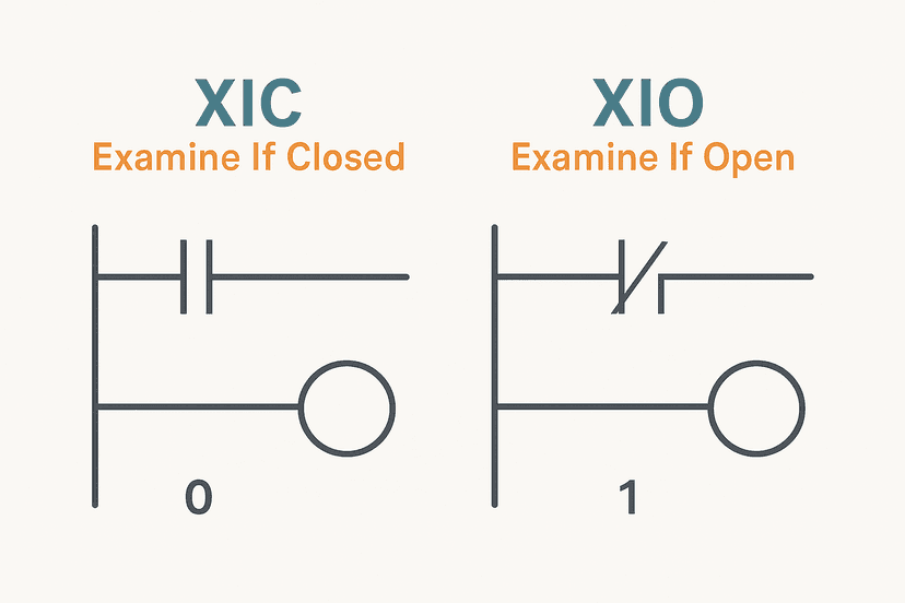
If you are using XIC and XIO contacts correctly, the SR pattern becomes very readable: XIC contacts gate the Set rung, XIO contacts guard against invalid states, and the OTL and OTU coils make the intent explicit. That readability matters when a maintenance tech is troubleshooting at 2 AM with a laptop and no documentation. And if you want to understand why normally open and normally closed contacts map to XIC and XIO the way they do, that groundwork makes the SR pattern much easier to reason about.
Keep Learning
The SR flip-flop is a building block, not an end in itself. Once you have it solid, the next step is seeing how one-shots and latches work together in real sequencer designs. Start with One-Shot Rising Edge in Ladder Logic to understand how to trigger a latch on a transition rather than a sustained condition. Then look at Ladder Logic Interlocks to see how SR latches chain together in safety-critical logic. If you are preparing for a technical interview, Ladder Logic Interview Questions covers SR flip-flop questions in the format interviewers actually use.
Frequently asked questions
What is a set-reset flip-flop in PLC ladder logic?
What is the difference between a seal-in rung and an SR latch?
Does a set-reset latch retain its state through a PLC power cycle?
What happens if Set and Reset are both true at the same time?
When should I use OTL and OTU instead of a regular OTE coil?
Can the same BOOL tag have an OTE coil and an OTL or OTU coil in the same program?
How do I reset an SR latch from an HMI?
Is a set-reset flip-flop the same as a latching relay?
How do I implement an SR flip-flop in Siemens TIA Portal?
Now build it
You have just read about OTL and OTU and XIO. Reading a rung and making one behave are different skills, and the second one is the job.
State Coil / Fault Coil
Intermediateabout 15 minA fault lamp that latches ON when any alarm condition occurs, even briefly, and only clears on Reset. And if the condition is still present when Reset is released, the fault comes right back.
Build this rungFree, no signup, runs in your browser. See all 16 exercises.
Was this helpful?