Retentive Timer in PLC Ladder Logic Explained
Most PLC timers reset the moment their enable rung goes false. That is exactly what you want for a simple on-delay. But sometimes you need a timer that remembers how long something has been running, even across interruptions, shift changes, or a power blip. That is what a retentive timer does, and it behaves differently enough from a standard TON that it trips up engineers who have only ever used the non-retentive kind.
What Is a Retentive Timer in PLC Programming?
A retentive timer in PLC programming is a timer instruction that accumulates elapsed time across multiple enable pulses and holds that accumulated value when the enable rung goes false or power is removed. Unlike a standard on-delay timer, it does not reset automatically. The accumulated value only clears when a dedicated reset instruction targets the timer, making it ideal for tracking cumulative time over many intermittent cycles.
Retentive Timer vs Non-Retentive Timer: The Core Difference
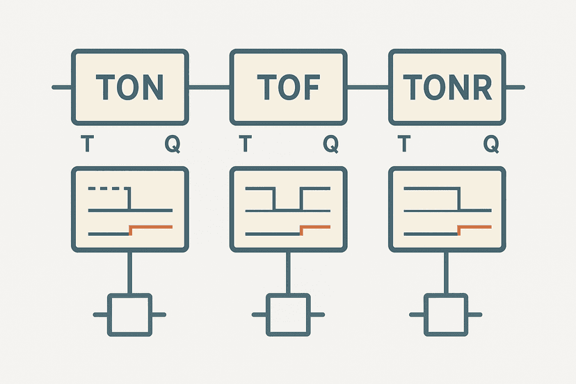
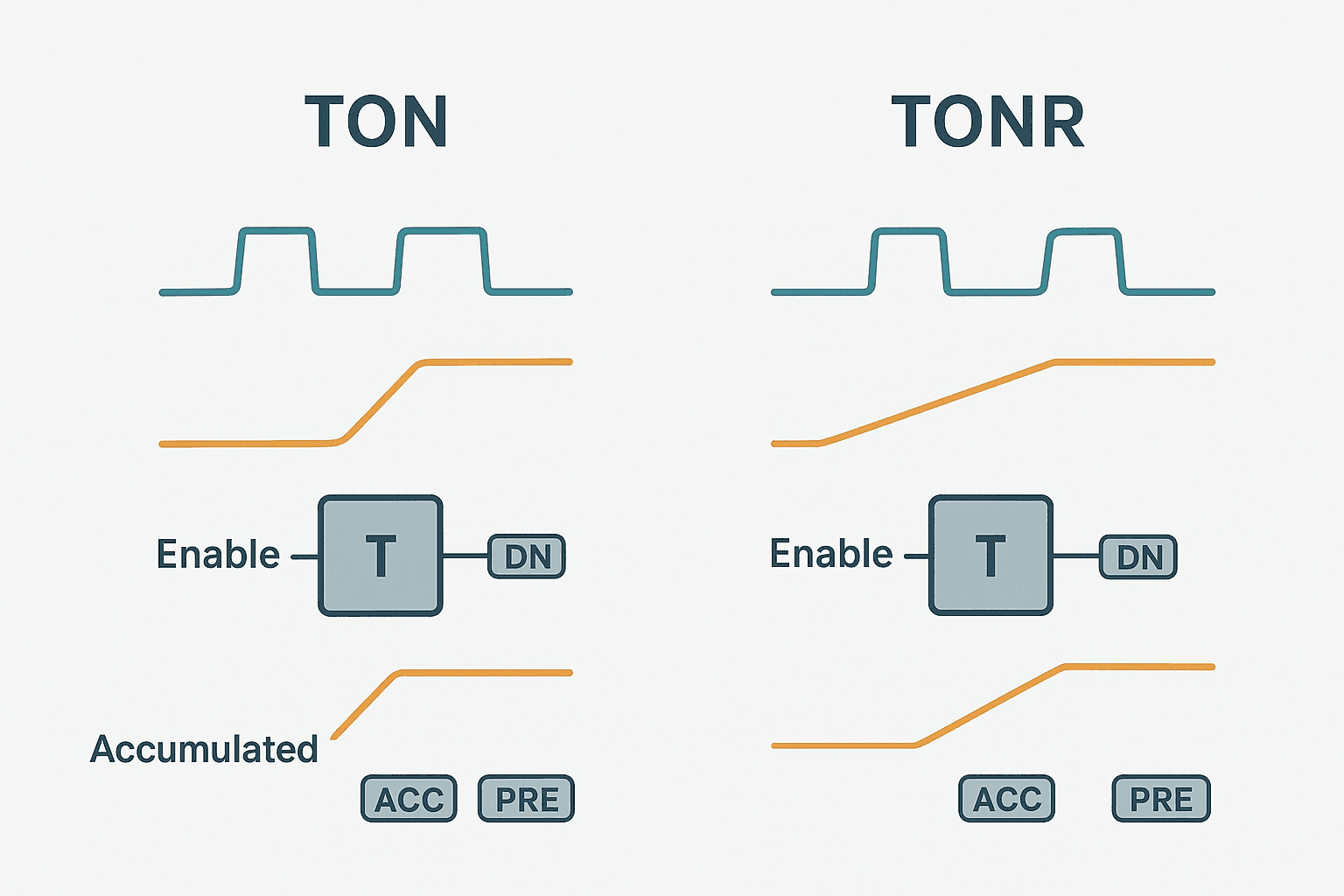
If you already understand TON, TOF and TONR and how they differ, you know the basic shape. But it is worth being precise about what actually happens at the bit level, because the timing diagram tells the whole story.
With a TON, the accumulated value (ACC) climbs while the rung is true. The moment the rung goes false, ACC snaps back to zero. Next time the rung goes true, it starts from scratch. With a TONR, ACC climbs while the rung is true, then freezes when the rung goes false. Next true rung, it continues from the frozen value. Only an explicit RES instruction brings ACC back to zero.
| Behaviour | TON (non-retentive) | TONR (retentive) |
|---|---|---|
| Rung goes false | ACC resets to 0 | ACC holds current value |
| Power cycle (non-retain tag) | ACC resets to 0 | ACC resets to 0 |
| Power cycle (retain tag / DB) | ACC resets to 0 | ACC survives |
| DN bit when ACC >= PRE | Sets, resets on rung false | Sets, stays set until RES |
| How to clear ACC | Rung going false | Explicit RES instruction only |
TONR in Studio 5000: Instruction Details
In Studio 5000 the TONR instruction uses exactly the same TIMER data type as TON and TOF. The structure has three members: PRE (preset in milliseconds), ACC (accumulated milliseconds) and three status bits: EN (enable, true while rung is true), TT (timer timing, true while ACC < PRE and rung is true) and DN (done, true when ACC >= PRE). You declare the tag as TIMER, drop TONR on the rung, and set PRE to your target value.
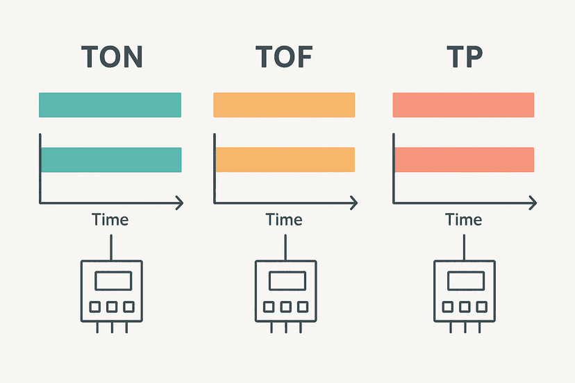
The reset works with a standard RES instruction on a separate rung. Point RES at the same tag name. When that rung fires true for one scan, ACC clears to zero and DN clears. The TONR is then ready to accumulate again from the next true enable rung. This is different from the TON vs TOF vs TP timer comparison, where TON handles its own reset without needing RES.
Studio 5000 Tag Declaration
// Tag declarations in Controller Tags
Motor1_RunTimer     : TIMER   // PRE = 3600000 ms (1 hour)
Motor1_RunHours     : INT     // accumulated full hours
Reset_RunTimer_Cmd  : BOOL    // from HMI maintenance screen

// Rung 1 - TONR accumulates while motor is running
// TONR(Motor1_RunTimer, 3600000, 0)
// Enable: Motor1_RunFB (run feedback from drive)

// Rung 2 - When 1 hour accumulates, increment hour counter
// XIC(Motor1_RunTimer.DN) OSR(RunHour_OS) ADD(Motor1_RunHours, 1, Motor1_RunHours)

// Rung 3 - Reset timer after each hour so it cycles
// XIC(Motor1_RunTimer.DN) RES(Motor1_RunTimer)

// Rung 4 - Manual maintenance reset of hour counter
// XIC(Reset_RunTimer_Cmd) MOV(0, Motor1_RunHours)
That pattern is the classic run-hour meter. The TONR accumulates for 3,600,000 ms (one hour). When DN fires, a one-shot increments the integer counter and the RES on rung 3 clears the timer so it cycles. The hour count keeps growing, unaffected by shift changes or short power interruptions as long as the tag is configured as retain. This pairs nicely with PLC counter instructions when you want a hard batch or maintenance limit.
TONR in TIA Portal: The IEC Way
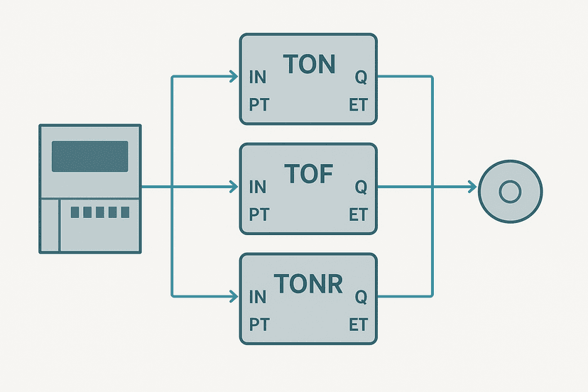
TIA Portal follows IEC 61131-3, so the retentive timer is simply called TONR as well, but the pin names differ from Rockwell. The S7-1200 and S7-1500 both support it. The block has these pins: IN (enable, same role as Logix enable rung), R (reset, clears ET to zero), PT (preset time, uses T# notation like T#30m), Q (done bit, equivalent to DN) and ET (elapsed time, TIME type).
You instantiate TONR inside a function block and it automatically gets an instance data block, which is exactly how the S7-1200 timers in TIA Portal work for all IEC timer types. To make the accumulated time survive a CPU power cycle, open the instance DB properties in TIA Portal and enable the 'Retain' attribute on the #ET member. Without that, the S7-1200 will reset ET to T#0s on every power-up even though the instruction is retentive during normal running.
Real-World Use Cases for Retentive Timers
Knowing when to reach for TONR instead of TON is half the battle. Here are the cases where it genuinely earns its place:
- Motor run-hour tracking. Accumulate total run time across shifts to trigger a greasing or bearing-change alert. A TON would lose the count every time the motor stops.
- UV lamp exposure metering. UV disinfection lamps degrade with total exposure hours, not calendar time. TONR gives you the actual on-time regardless of how often the system cycles.
- Valve open-time accumulation. On a water treatment plant, some regulations require you to log total open time for dosing valves. TONR makes this straightforward.
- Cumulative fault exposure. Track how long a temperature has been above a warning threshold (not continuously, but in total) before escalating to a shutdown alarm.
- Maintenance interval timers. Replace time-based preventive maintenance counters with actual run-time-based ones. A machine running two shifts versus one shift needs service at the right hours, not calendar days.
On a bottling line I commissioned a few years back, the customer wanted a grease interval alert on the main conveyor gearbox. We originally used a calendar timer on the HMI, but the line ran weekends only in summer and five days a week in winter. The grease interval kept firing too early in summer and too late in winter. Swapping to a TONR-based run-hour counter fixed it permanently. The PLC bottle filling machine project gives you a sense of how many small timers a packaging line actually needs.
Retentive Timer Ladder Example: Gearbox Grease Interval Alert
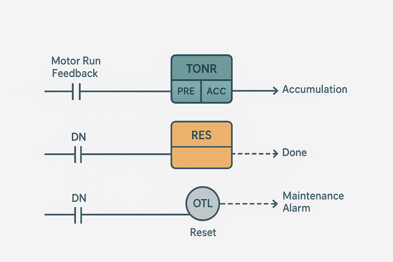
TONR Gearbox Run-Hour Alert with HMI Reset (Studio 5000). Ladder logic (4 rungs): Rung 0: examine if Conv_Motor_RunFB is on (XIC), then TONR on Gearbox_RunTimer. Rung 1: examine if Gearbox_RunTimer.DN is on (XIC), then examine if Grease_Alert_OS is on (XIC), then latch output Gearbox_Grease_Due (OTL). Rung 2: examine if Gearbox_RunTimer.DN is on (XIC), then RES on Gearbox_RunTimer. Rung 3: examine if Gearbox_Grease_Due is on (XIC), then examine if HMI_GreaseAck is on (XIC), then unlatch output Gearbox_Grease_Due (OTU). Rung 1: TONR accumulates while the conveyor motor run feedback is true. PRE = 14,400,000 ms (4 hours of actual run time). Rung 2: When DN fires, a one-shot latches the grease-due alarm and rung 3 immediately resets the timer so the cycle restarts. Rung 4: The operator acknowledges on the HMI to clear the alarm. The timer keeps accumulating the next 4 hours regardless of how many stops occur between greasing events.
The diagram above evaluates one scan. Run these exact rungs on a real scan cycle to watch the latching and the timers behave.
Run this in the simulatorRetentive Timers and the Scan Cycle: A Timing Gotcha
Because TONR uses the PLC's time-of-day clock or scan-based elapsed time, very short enable pulses shorter than one scan may not accumulate any time. The PLC scan cycle evaluates each rung once per scan, so if an enable signal toggles true then false within a single scan, TONR sees it as false for that scan and accumulates nothing. For most maintenance-interval applications this is irrelevant because the events last seconds or hours. But if you are trying to accumulate very short process pulses, consider a different approach.
Also watch out for scan cycle problems when multiple TONR timers are in the same task with a long scan time. A 50 ms scan on a slow task means your 100 ms preset fires somewhere between 100 ms and 150 ms. For run-hour metering this error is irrelevant, but it matters for precision timing. The PLC scan cycle problems post covers that in detail.
Memory Retention: Will the Value Survive a Power Loss?
This is the question that catches people out. The retentive in TONR refers to retaining value when the rung goes false, not necessarily across a power cycle. Whether ACC survives a power-off depends entirely on how the tag memory is configured:
- Studio 5000 / Logix5000: Store the TIMER tag in a retentive data file or mark the UDT member as retentive in the controller properties. Standard controller tags are non-retentive by default.
- TIA Portal S7-1200 / S7-1500: Set the Retain attribute on the instance DB or on the specific member. The S7-1200 uses a backup battery or supercapacitor for retentive memory. Check the S7-1200 data blocks guide for how instance DBs handle retain.
- Mitsubishi GX Works3: Use the ST timer (retentive) and back it with a latch memory range configured in the PLC parameters.
- CODESYS: Declare the TONR variable with the RETAIN keyword or in a RETAIN VAR block.
Retentive Timer in Mitsubishi and Other Platforms
Mitsubishi uses a different naming convention. In GX Works3 classic (non-IEC) mode, regular timers are addressed as T0 to T511 and retentive timers as ST0 to ST127. The ST coil accumulates on each true scan and holds on false. You reset an ST timer with RST ST0. In IEC mode via GX Works3, the TONR function block works the same as in CODESYS or TIA Portal.
Omron Sysmac uses the TIML (long retentive timer) instruction in classic CX-Programmer, and the TONR function block in Omron Sysmac Studio following IEC 61131-3. The reset pin behaviour is identical to TIA Portal: R true clears ET regardless of IN state.
Common Mistakes with Retentive Timers
- No reset path. The timer DN latches and never clears. Any output gated on DN stays permanently energised after the first trigger.
- Forgetting retain configuration. The timer resets on every power cycle, making run-hour tracking useless. Verify retain settings before commissioning.
- Resetting too eagerly. Placing the RES rung on the same condition as the enable rung means the timer resets every time you want it to run. Separate the reset trigger clearly.
- Using TONR where TON is correct. If you want the timer to restart from zero every time the condition is met (like a watchdog or debounce timer), TON is right and TONR will give you confusing cumulative behaviour.
- Not testing the power-loss scenario. Always cycle power during FAT to confirm the retained value survives and the reset path works after restart.
Keep Learning
If you want to go deeper on how all three Rockwell timer types compare side by side, the TON, TOF and TONR timers explained post covers the timing diagrams and bit behaviour in detail. For Siemens-specific implementation, S7-1200 Timers in TIA Portal walks through the IEC TONR block step by step. And if you are combining retentive timers with counters to build a maintenance tracking system, PLC Counter Instructions: CTU, CTD and CTUD Explained is the natural next read.
Frequently asked questions
What is a retentive timer in a PLC?
What is the difference between a retentive timer and a non-retentive timer?
How do you reset a TONR timer in Studio 5000?
Does a retentive timer keep its value through a power cycle?
When should I use a retentive timer instead of TON?
What is the TONR instruction in Rockwell Studio 5000?
How is TONR implemented in TIA Portal?
Can I use a retentive timer to track motor run hours in a PLC?
What happens if I forget to add a RES instruction for a TONR?
Does a retentive timer exist in Mitsubishi GX Works3?
Now build it
You have just read about RTO and RES. Reading a rung and making one behave are different skills, and the second one is the job.
Service Interval (RTO + RES)
Advancedabout 18 minTotal ACCUMULATED run-time, across any number of stop/starts, must trigger a service lamp at 3 seconds. A normal TON forgets on every stop; the retentive RTO remembers until you RES it.
Build this rungFree, no signup, runs in your browser. See all 16 exercises.
Was this helpful?