PLC Timer Ladder Logic: 5 Practical Examples
Timers are the instruction you will write more than almost anything else in a PLC career. And yet, the gap between knowing what a TON does in theory and building a circuit that actually behaves the way the machine needs it to is surprisingly wide. The examples below are built from real applications: a fan purge sequence, a valve open-delay, a clamp dwell, a sensor debounce and a timed warning alarm. Each one shows not just the rung, but why it is structured that way.
What Are Timer Ladder Logic Examples?
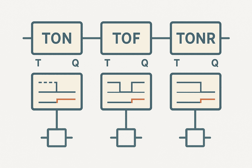
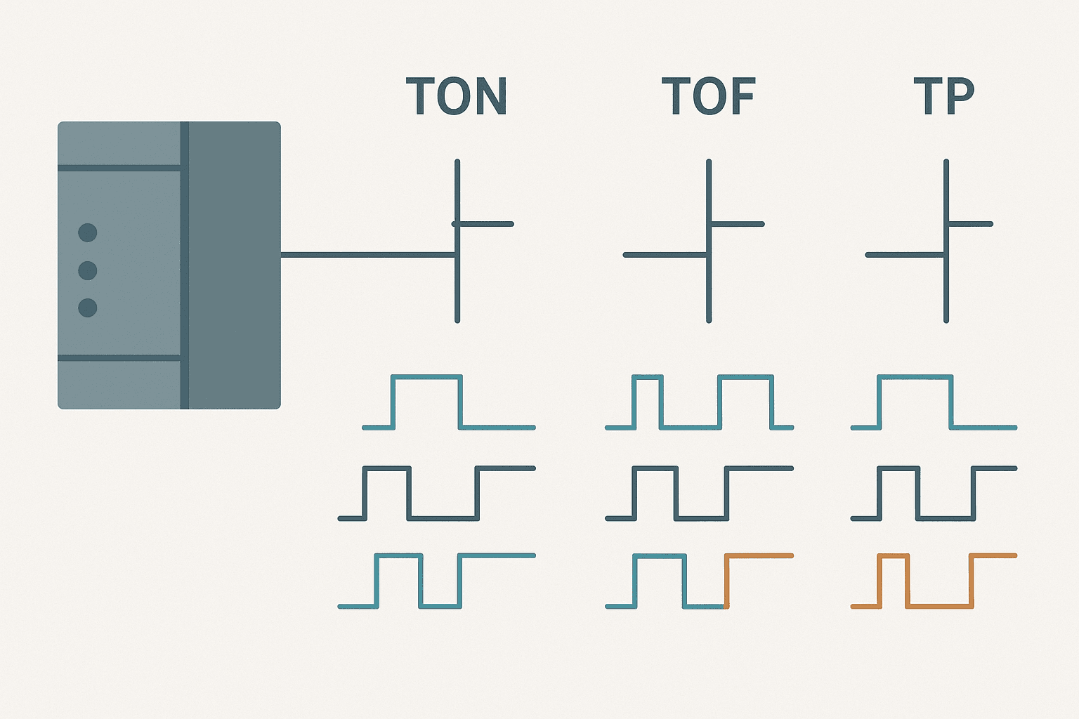
Timer ladder logic examples are complete, working rungs that use TON (on-delay), TOF (off-delay) or TP (pulse) timer instructions to control the timing of outputs in a PLC program. Each example combines the timer instruction with enabling contacts, output coils and reset logic to solve a specific real-world sequencing or delay problem. Understanding these patterns lets you adapt them to any platform or application.
Timer Instruction Quick Reference
| Instruction | Output goes ON when... | Accumulator resets when... | Typical use |
|---|---|---|---|
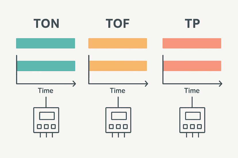
| TON | Rung TRUE for >= preset time | Rung goes FALSE | Start delays, dwell timers, confirmation windows |
| TOF | Rung goes TRUE immediately; stays ON for preset after rung goes FALSE | Rung goes TRUE again | Fan purge, lube run-down, coast-to-stop |
| TP | Rung rises TRUE; output ON for exactly preset time | Pulse completes (cannot re-trigger mid-pulse) | Solenoid pulses, reject ejectors, one-shot events |
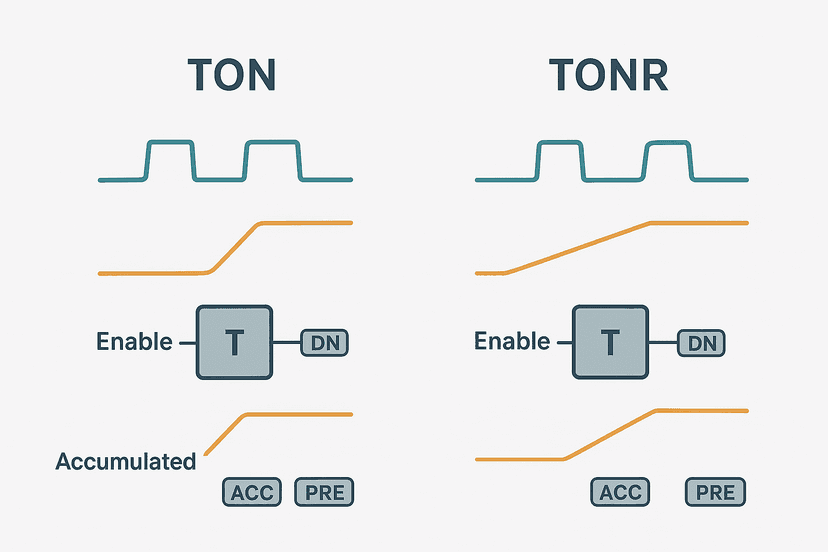
| TONR | Rung TRUE for >= accumulated preset (retentive) | Only on explicit RES or RESET input | Run-hour meters, maintenance timers |
If you need a deeper comparison of the three main types before reading the examples, the TON, TOF and TONR timers explained post covers the edge cases, and the TON vs TOF vs TP comparison goes side-by-side on timing diagrams. For the Siemens side, see S7-1200 Timers in TIA Portal.
Example 1: TON Valve Open-Delay Before Pump Start
This is one of the most common patterns in process plants. You open an inlet valve and wait two seconds for it to fully stroke before the pump starts. Starting the pump against a closed valve hammers the impeller and causes premature wear. The TON timer sits between the valve command and the pump enable.
TON Valve Stroke Delay Before Pump Start (Studio 5000). Ladder logic (4 rungs): Rung 0: examine if Sys_Ready is on (XIC), then examine if HMI_StartCmd is on (XIC), then examine if Pump_FaultLatch is off (XIO), then latch output InletValve_Open (OTL). Rung 1: examine if InletValve_Open is on (XIC), then TON on Valve_StrokeDelay. Rung 2: examine if Valve_StrokeDelay.DN is on (XIC), then examine if Pump_FaultLatch is off (XIO), then latch output Pump_Run (OTL). Rung 3: examine if HMI_StopCmd is on (XIC), then unlatch output Pump_Run (OTU), then either unlatch output InletValve_Open (OTU), then either RES on Valve_StrokeDelay. Rung 1 latches the inlet valve open only when the system is ready, the HMI start is pressed and there is no pump fault. Rung 2 runs the TON timer while the valve is open. Rung 3 latches the pump run bit only after the 2-second stroke delay completes. Rung 4 unlatches both the pump and the valve on a stop command and resets the timer so the next start is clean. The RES on the timer is important: without it the timer accumulator stays at preset and the pump would start instantly on the very next cycle.
The diagram above evaluates one scan. Run these exact rungs on a real scan cycle to watch the latching and the timers behave.
Run this in the simulatorExample 2: TOF Fan Purge After Oven Shutdown
An exhaust fan must keep running for 90 seconds after an oven burner shuts off to clear residual fumes. This is a textbook TOF application. The fan output goes true the instant the burner runs (TOF output is true while the enabling rung is true), and stays true for 90 seconds after the burner stops.
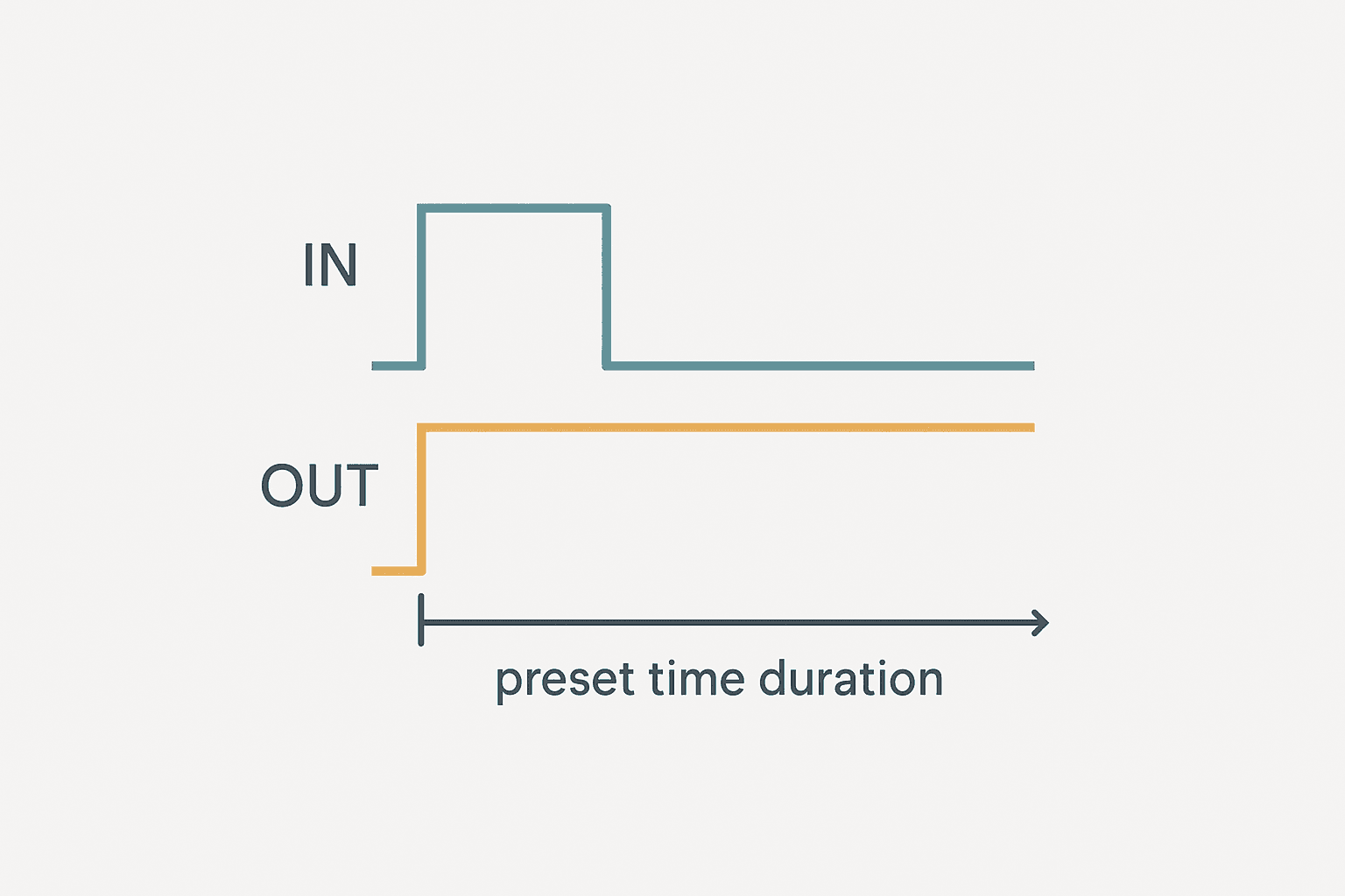
In Studio 5000 the TOF instruction's output bit (.DN) behaves the opposite way to TON: it is true when the rung is true AND during the off-delay period, and it goes false when the accumulator reaches the preset after the rung drops. Use the .DN bit to drive the fan output coil directly.
// Rung 1: Fan run with 90-second purge delay after burner stops
XIC(Burner_Running)XIO(Fan_FaultLatch)TOF(Fan_PurgeTimer,T#90s,0)
XIC(Fan_PurgeTimer.DN)OTE(ExhaustFan_Out)

// Rung 2: Fault latch if fan feedback drops while output is commanded
XIC(ExhaustFan_Out)XIO(Fan_RunFB)TON(Fan_FBTimeout,T#5s,0)
XIC(Fan_FBTimeout.DN)XIO(Fan_RunFB)OSR(Fan_Fault_OS)OTL(Fan_FaultLatch)

// Rung 3: Acknowledge clears fault only when fan is not running
XIC(Fan_FaultLatch)XIC(HMI_FanFaultAck)XIO(ExhaustFan_Out)OTU(Fan_FaultLatch)
The run-confirmation fault latch on rungs 2 and 3 is not strictly part of the TOF logic, but you should always include it. If the fan contactor fails or the PLC output faults, you want the operator to know before the oven cools and someone opens the door. The ladder logic interlocks guide explains the general interlock pattern in more detail.
Example 3: TP Pulse Timer for a Clamp Solenoid
A pneumatic clamp solenoid needs a 300 ms energise pulse to latch the clamp mechanism. Holding the solenoid on continuously wastes energy and overheats the coil. A TP timer gives you exactly 300 ms every time the part-present sensor triggers, regardless of how long the sensor stays high.
The key thing to understand about TP: you cannot re-trigger it mid-pulse. If another part arrives while the pulse is running, you need a queue bit, exactly like the reject ejector example in the already-published PLC Bottle Filling Machine project. For this clamp application the machine design ensures only one part at a time, so a simple TP is enough.
// Rung 1: Rising edge on part sensor fires the TP pulse
XIC(PartPresent_Sensor)OSR(Part_Arrive_OS)TP(Clamp_PulseTimer,T#300ms,0)

// Rung 2: Solenoid output follows the TP output bit
XIC(Clamp_PulseTimer.Q)OTE(Clamp_Sol_Out)

// Rung 3: Verify clamp confirms within 400 ms window (TON watchdog)
XIC(Clamp_Sol_Out)XIO(Clamp_ConfirmLS)TON(Clamp_ConfirmTimeout,T#400ms,0)
XIC(Clamp_ConfirmTimeout.DN)XIO(Clamp_ConfirmLS)OSR(Clamp_Fault_OS)OTL(Clamp_FaultLatch)Example 4: TON Sensor Debounce for a Vibrating Proximity Switch
On a stamping press I worked on, a proximity sensor detecting the ram home position was mounted close enough to the die that it vibrated every stroke. The input would chatter for 15 to 20 ms before settling. That chatter was incrementing a counter on every bounce and the batch count was reading 3 to 4 times the actual part count by end of shift.
The fix is a software debounce using a TON. The raw input must be continuously true for the debounce period before the clean signal bit is set. Any gap resets the timer. This is cheaper and faster to implement than adding an input filter module, though you can also do both. The PLC digital input faults guide covers hardware-level filtering options.
// Rung 1: Raw input must be stable for 25 ms before clean bit sets
XIC(RamHome_Raw)TON(RamHome_Debounce,T#25ms,0)
XIC(RamHome_Debounce.DN)OTE(RamHome_Clean)

// Rung 2: Rising edge of clean bit increments part counter
XIC(RamHome_Clean)OSR(RamHome_Rise_OS)CTU(Press_PartCounter,9999,0)

// Rung 3: Counter done latches batch complete alarm
XIC(Press_PartCounter.DN)OSR(Batch_Done_OS2)OTL(Batch_Done_Latch2)
XIC(Batch_Done_Latch2)XIC(HMI_BatchReset2)OTU(Batch_Done_Latch2)[RES(Press_PartCounter)]
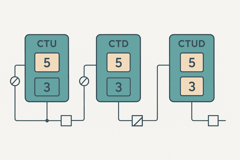
Notice the OSR on rung 2. Without it, the counter would increment on every scan while RamHome_Clean is true, not just once per stroke. That is the same chatter problem in software. The one-shot rising edge guide explains the OSR instruction in full. For counter behaviour, see PLC counter instructions: CTU, CTD and CTUD.
Example 5: Cascaded TON Timers for a 3-Stage Warning Alarm
Some processes need a graduated alarm: a first warning at 30 seconds, a second warning at 60 seconds and a shutdown at 90 seconds of continuous abnormal condition. Cascaded TON timers handle this cleanly. Each timer starts from the same enabling condition, so they run in parallel, not in series. You do not need to chain them.
// Rung 1: All three timers share the same enable condition
XIC(PressureLow_Raw)XIO(Press_Shutdown)TON(Alarm_Warn1,T#30s,0)
XIC(PressureLow_Raw)XIO(Press_Shutdown)TON(Alarm_Warn2,T#60s,0)
XIC(PressureLow_Raw)XIO(Press_Shutdown)TON(Alarm_Shutdown,T#90s,0)

// Rung 2: Outputs energise as each timer reaches its preset
XIC(Alarm_Warn1.DN)XIO(Alarm_Warn2.DN)OTE(HMI_Warn1_Active)
XIC(Alarm_Warn2.DN)XIO(Alarm_Shutdown.DN)OTE(HMI_Warn2_Active)
XIC(Alarm_Shutdown.DN)OSR(Shutdown_OS)OTL(Press_Shutdown)

// Rung 3: Shutdown latches; clear only when condition is gone
XIC(Press_Shutdown)XIC(HMI_ShutdownAck)XIO(PressureLow_Raw)OTU(Press_Shutdown)
Running timers in parallel like this keeps the logic flat and easy to read. If you chain them (start timer 2 from timer 1's .DN bit), the second and third timers measure time from the previous stage, not from the original fault. That is often not what you want, and it is a common mistake I have had to correct on multiple commissioning jobs.
Common Timer Mistakes and How to Avoid Them
- Forgetting to RES a TON after a stop command. The timer holds its accumulated value, so the next start skips the delay entirely. Always put RES on the stop path.
- Using a TOF where a TON is needed (or vice versa). If you are confused, sketch the timing diagram first: draw the input signal, then draw what you want the output to do. TON delays the ON, TOF delays the OFF.
- Timer preset in wrong units. On older SLC 500 or MicroLogix platforms the preset is in time-base units, not milliseconds. A preset of 500 with a 10 ms time base gives 5 seconds, not 500 ms. Modern Logix and IEC platforms use TIME literals (T#500ms) which removes this ambiguity.
- Scan time longer than the preset. If your scan is 20 ms and your preset is 10 ms, the timer will never fire. Keep presets at least 5 to 10 times the maximum scan time.
- Re-triggering a TP timer mid-pulse. The TP output will not extend; the extra trigger is silently ignored unless you add a queue latch as described in Example 3.
- Not accounting for timer reset behaviour on power loss. TON and TOF reset their accumulators on power cycle. TONR does not. Choose the right type for your application, and check the retentive timer guide if you need to survive a power interruption.
When something seems wrong with a timer circuit, PLC troubleshooting with online monitoring is your fastest diagnostic tool. Watch the .ACC value increment in real time and you will immediately see if the rung is going false prematurely, or if the timer is resetting unexpectedly. The scan cycle troubleshooting guide covers the scan-related timing problems in more depth.
Applying These Patterns to Other Platforms
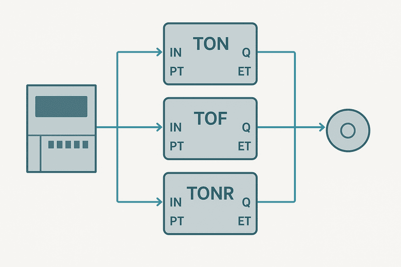
All five examples above are written in Studio 5000 notation, but the logic maps directly to other platforms. Siemens IEC 61131-3 TON uses the same IN/PT/Q/ET structure. Mitsubishi GX Works3 uses OUT T with a set value. Omron Sysmac Studio uses the IEC TON function block. The concepts are identical; only the syntax changes. The GX Works3 getting-started guide and the Omron Sysmac Studio guide both cover the timer instructions specific to those platforms.
If you want to test any of these circuits before you have hardware available, see how to simulate ladder logic without a PLC. For understanding the wider context of how timer tags live in memory alongside other tags, the PLC memory and addressing explained post is worth reading alongside this one.
What to Read Next
If these examples have raised questions about which timer type to choose for a specific situation, the TON vs TOF vs TP comparison gives you side-by-side timing diagrams and a decision table. For the retentive variant used in run-hour and maintenance counters, the retentive timer in PLC ladder logic guide covers TONR in depth. And if you want to combine timers with counters in a sequencer, PLC counter instructions: CTU, CTD and CTUD is the natural next step.
Frequently asked questions
What is a TON timer in ladder logic?
What is the difference between TON and TOF in PLC ladder logic?
What is a TP timer used for in ladder logic?
Can a TON timer in Studio 5000 lose its accumulated value on a power cycle?
Why does my TON timer reset before it reaches the preset?
How do I wire a sensor to trigger a PLC timer?
What time base should I use for PLC timers?
Can I use a timer output to trigger a counter in ladder logic?
What happens if the PLC scan time is longer than my timer preset?
How do I reset a TON timer in ladder logic?
Now build it
You have just read about TON. Reading a rung and making one behave are different skills, and the second one is the job.
Flasher
Intermediateabout 15 minTwo timers chained in a loop make a lamp blink: the classic two-TON flasher used for warning beacons everywhere. Your first taste of timers driving each other.
Build this rungFree, no signup, runs in your browser. See all 16 exercises.
Was this helpful?