RTD vs Thermocouple: Which Should You Wire to Your PLC?
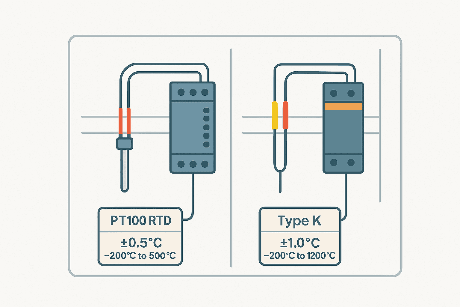
You are spec'ing a temperature loop for a PLC panel and the datasheet gives you a choice between a PT100 RTD and a Type K thermocouple. Both measure temperature. Both wire to a dedicated input module. But the right choice can mean the difference between a stable, accurate loop and a headache of drift, noise and unexplained offset. Here is how to make the call confidently.
RTD vs Thermocouple: What Is the Core Difference?
An RTD (Resistance Temperature Detector) measures temperature by detecting how the electrical resistance of a metal element, almost always platinum, changes with heat. A thermocouple generates a small voltage, typically in the millivolt range, from the Seebeck effect at the junction of two dissimilar metal wires. RTDs are more accurate and stable. Thermocouples cover a wider temperature range, respond faster and cost less per sensor. Those four differences drive almost every selection decision you will make.
Working Principle: How Each Sensor Generates Its Signal
How an RTD Works
A PT100 RTD has exactly 100 ohms of resistance at 0 degrees C. For every degree C rise in temperature, resistance climbs roughly 0.385 ohms. Your PLC's RTD input module forces a small, known excitation current (typically 1 mA) through the element, measures the resulting voltage, and back-calculates resistance and then temperature. The platinum element is stable, repeatable and has a well-characterised relationship defined in IEC 60751. PT1000 works on the same principle but at 1000 ohms, which makes lead resistance a much smaller percentage of the total and simplifies 2-wire installations.
How a Thermocouple Works
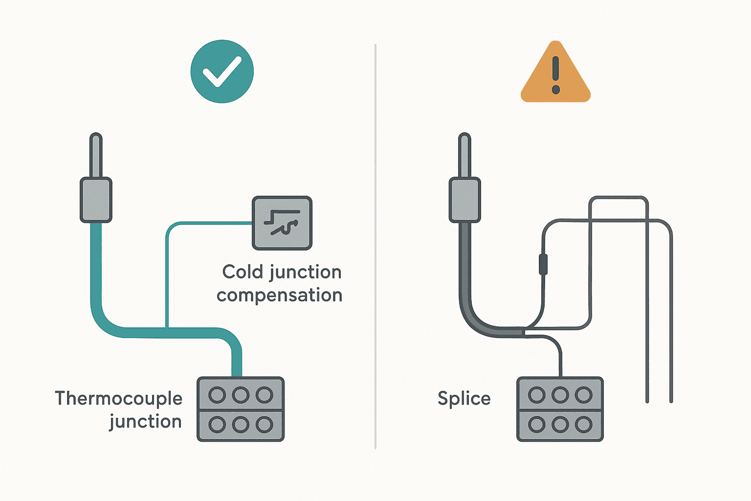
A thermocouple is two wires of different alloys welded together at one end, the hot junction. The open ends, the cold junction, sit at your input module's terminal block. The temperature difference between hot and cold produces a voltage, around 40 microvolts per degree C for Type K. The problem is that the module only sees the net voltage, so it must also measure its own terminal temperature and compensate. That process is called cold junction compensation (CJC), and any error in the CJC becomes a direct offset error on the measurement.
RTD vs Thermocouple Accuracy: Real Numbers
This is where RTDs win decisively for most PLC temperature control loops. A Class B PT100 per IEC 60751 is accurate to plus or minus 0.3 degrees C at 0 degrees C, degrading to about plus or minus 1.3 degrees C at 300 degrees C. A Class A PT100 tightens that to plus or minus 0.15 degrees C at 0 degrees C. A typical industrial Type K thermocouple sits at Class 1 accuracy: plus or minus 1.5 degrees C or plus or minus 0.4 percent of reading, whichever is greater. Add a conservative plus or minus 0.5 to 1 degree C for CJC error in a warm control panel and you are looking at 2 degrees C total error on a good day. On a food processing line where a 1 degree C setpoint deviation matters for pasteurisation validation, that is a problem.
Temperature Range: Where Thermocouples Pull Ahead
Platinum RTDs top out around 600 to 850 degrees C depending on construction. Below minus 200 degrees C, they become impractical. Thermocouples have a much wider span. Type K runs from minus 200 to plus 1260 degrees C. Type S and Type R push to 1600 degrees C and above, making them the only practical choice for furnace and kiln applications. If your process exceeds 600 degrees C, the thermocouple is not just the better choice, it is often the only choice.
| Property | PT100 RTD | Type K Thermocouple |
|---|---|---|
| Typical accuracy | +/- 0.1 to 0.5 deg C | +/- 1.5 to 2.5 deg C (inc. CJC) |
| Temperature range | -200 to 600 deg C | -200 to 1260 deg C |
| Response time (bare) | 0.5 to 5 s | 0.05 to 0.5 s |
| Signal type | Resistance (ohms) | Voltage (mV) |
| Cable type | Standard copper | Type K extension wire only |
| Typical cost (sensor only) | Higher | Lower |
RTD vs Thermocouple Wiring to a PLC
2-Wire, 3-Wire and 4-Wire RTD Connections
RTD wiring configuration matters because the resistance of the copper cable adds directly to the measured resistance and introduces an error. A 10-metre run of 0.5 mm squared copper adds roughly 0.7 ohms each way, which translates to about 1.8 degrees C of offset on a PT100. That is unacceptable for a high-accuracy loop.
- 2-wire RTD: simplest connection, both lead resistances add to the reading. Use only for very short runs (under 3 metres) or with PT1000 where the lead error is proportionally tiny.
- 3-wire RTD: the standard for industrial PLC panels. The module measures one lead separately and subtracts it, assuming both leads are equal length and the same gauge. This works well if you follow that assumption. Most RTD modules, including the Rockwell 1756-IR6I and Siemens SM 1231 RTD, default to 3-wire mode.
- 4-wire RTD: uses separate excitation and sense conductors. Lead resistance is completely eliminated regardless of cable length. Specify this for validation-critical applications. Check that your module supports 4-wire mode before purchasing.
For more on keeping analog signals clean from the sensor to the module, the articles on shielding analog signal cables in PLC panels and cable shield grounding cover what you need to do with the screen.
Thermocouple Extension Wire: The Trap Most Engineers Hit Once
You cannot extend a thermocouple with standard copper cable. The moment you introduce a copper-to-Type-K alloy junction anywhere other than the module terminal, you create an unintended thermoelectric voltage that shifts your reading. You must use matched extension wire, colour-coded per IEC 60584-3: yellow overall sheath with yellow positive and red negative for Type K in Europe. In North America the colour coding differs (yellow positive, red negative, brown sheath), so double-check before ordering. RTDs have no such restriction. Standard screened copper cable works fine.
PLC Input Module Selection for RTD and Thermocouple
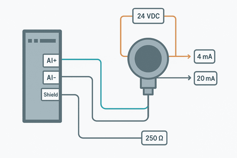
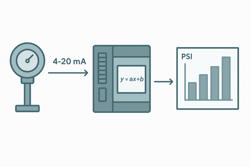
Never wire an RTD or thermocouple to a standard 4-20 mA analog input. You need a dedicated temperature input module or an external signal conditioner that outputs 4-20 mA. The signal conditioner approach is useful when your PLC chassis has no spare temperature module slots, and the conditioner's 4-20 mA output then connects normally to a standard analog input wired per the 4-20 mA guide. Once in the PLC, you scale the raw count to engineering units using the 4-20 mA scaling formula.
For direct module connections, check these key parameters before specifying:
- Sensor type support: confirm the module lists your exact RTD class (PT100, PT1000, Ni100) or thermocouple type (K, J, T, S). Not all modules support all variants.
- Wire configuration: verify 2-, 3- or 4-wire RTD support. Some budget modules only support 3-wire.
- Resolution: a 16-bit temperature module typically resolves to 0.1 degrees C. A 12-bit module resolves to roughly 0.5 to 1 degree C, which may not satisfy your accuracy budget.
- Conversion time: temperature modules are slow by PLC standards, 50 to 500 ms per channel is typical. Factor this into your scan cycle if you are running a fast PID loop.
- Isolation: isolated inputs prevent ground loops across multiple sensors at different electrical potentials. Worth the cost on larger installations.
The S7-1200 analog input configuration guide walks through the TIA Portal setup for Siemens temperature modules, including the parameter screens where you select RTD type and wire configuration. The types of PLC modules article covers the broader module family if you are still getting oriented.
Response Time: Does It Actually Matter for Your Application?
A bare Type K thermocouple junction responds in 50 to 100 ms. A bare PT100 element typically takes 0.5 to 5 seconds. In practice, both sensors are usually inside a stainless steel sheath inside a thermowell in a process pipe. Add a thermowell and the response time of either sensor stretches to 10 to 60 seconds depending on wall thickness and process flow. The intrinsic speed advantage of the thermocouple largely disappears. Response time becomes the deciding factor only for high-velocity gas streams, extrusion die monitoring or safety cutout loops where you need to catch a runaway in under 2 seconds.
Noise, Drift and Long-Term Stability
Thermocouples drift over time, especially after repeated thermal cycling or exposure to reducing atmospheres. Type K is particularly susceptible to a phenomenon called green rot at 650 to 900 degrees C, where the chromel leg oxidises selectively and the output shifts negative. RTDs are significantly more stable. A PT100 in a clean environment can hold calibration for years. If your process demands calibration intervals longer than 12 months, RTDs are the safer choice. For noisy electrical environments, the RTD's resistance signal is far less susceptible to induced mV-level interference than a thermocouple's millivolt output. Follow the control panel grounding guide and use screened cable, but know the RTD starts with a natural noise advantage.
How to Choose: A Practical Decision Guide
- Process temperature above 600 degrees C: thermocouple, no contest. Specify the alloy type based on atmosphere and whether you need to exceed 1260 degrees C.
- Accuracy better than plus or minus 1 degree C required: RTD, 3-wire or 4-wire PT100.
- Long cable runs in noisy panels: RTD. The higher signal level is less vulnerable to interference. Follow wire routing and segregation best practices regardless.
- Cost-sensitive application with many points: thermocouple. Sensors are cheaper and a multi-channel thermocouple module can be very cost-effective.
- Cryogenic or sub-zero temperatures: RTD with a type rated for low temperature, or Type T thermocouple.
- Validation-critical pharmaceutical or food process: 4-wire PT100 RTD with a calibrated module. The audit trail and uncertainty budget demand it.
If you pick up an intermittent temperature fault later in the project, the systematic approach in intermittent sensor fault troubleshooting will help you isolate whether the problem is the sensor, the extension cable or the module. And if the reading is stuck or obviously wrong at commissioning, the PLC analog output fault diagnosis article is a good template for thinking through analog measurement loops methodically, even on input channels.
Keep Learning
Once you have the right sensor selected and wired, the next step is getting the raw counts into engineering units inside your PLC. The 4-20 mA scaling in a PLC: ST and Ladder Code article shows both Structured Text and Ladder approaches that apply directly when you are using a signal conditioner output. If you are working on an S7-1200 with a native RTD module, the S7-1200 analog inputs guide walks through the full TIA Portal configuration. And for a broader look at how sensors, modules and the scan cycle all interact, how PLC input and output modules work is worth a read.
Frequently asked questions
What is the main difference between an RTD and a thermocouple?
Why is an RTD more accurate than a thermocouple?
Which temperature sensor has a faster response time, RTD or thermocouple?
What is a PT100 RTD?
What does cold junction compensation mean for a thermocouple?
Can I use a standard 4-20 mA analog input module for an RTD or thermocouple?
What is the difference between 2-wire, 3-wire and 4-wire RTD wiring?
What thermocouple types are most common in industrial PLC applications?
Do I need special extension cables for thermocouples?
When should I choose an RTD over a thermocouple for a PLC application?
Learn this by building it
There is a PLC in this site. It runs a real scan engine, checks your logic against the same tests a working machine would fail, and needs no download and no account.
Open the exercisesFree, no signup, runs in your browser. See all 16 exercises.
Was this helpful?