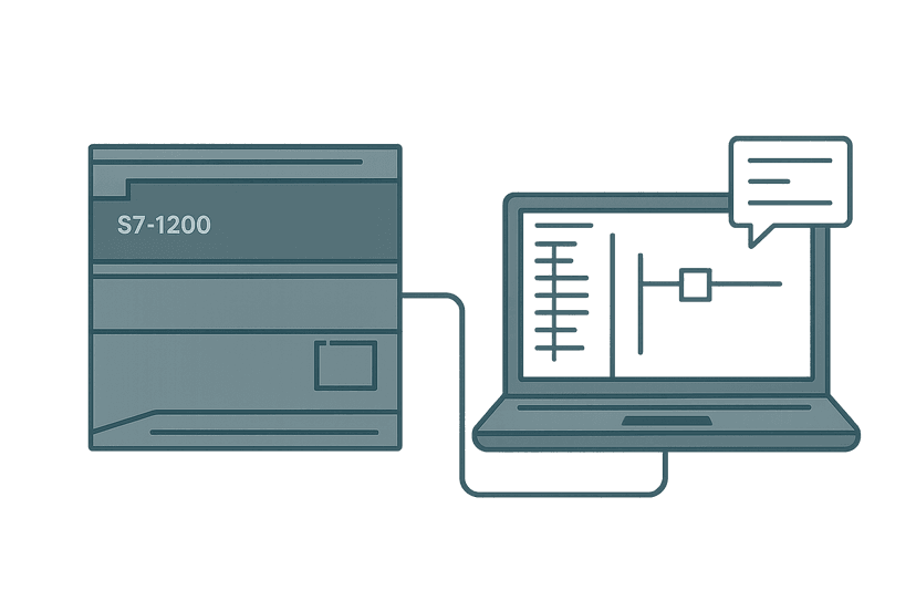
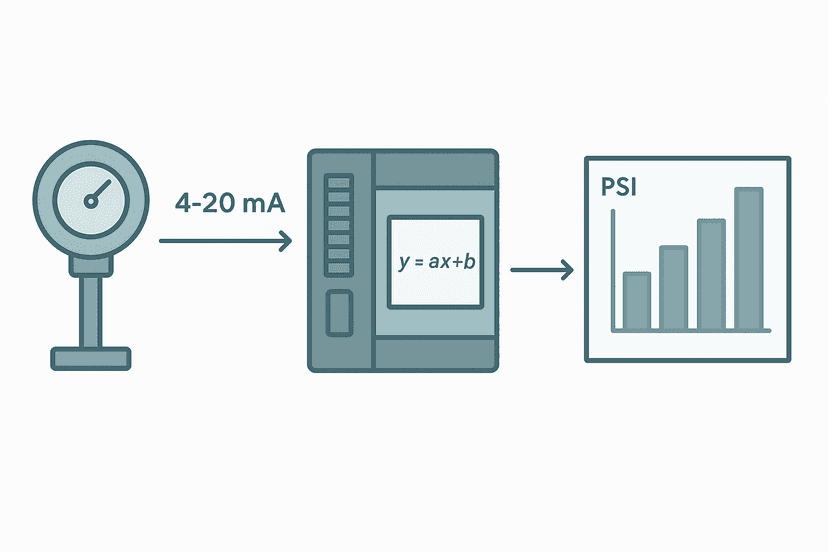
S7-1200 Analog Inputs: Wiring and TIA Portal Setup
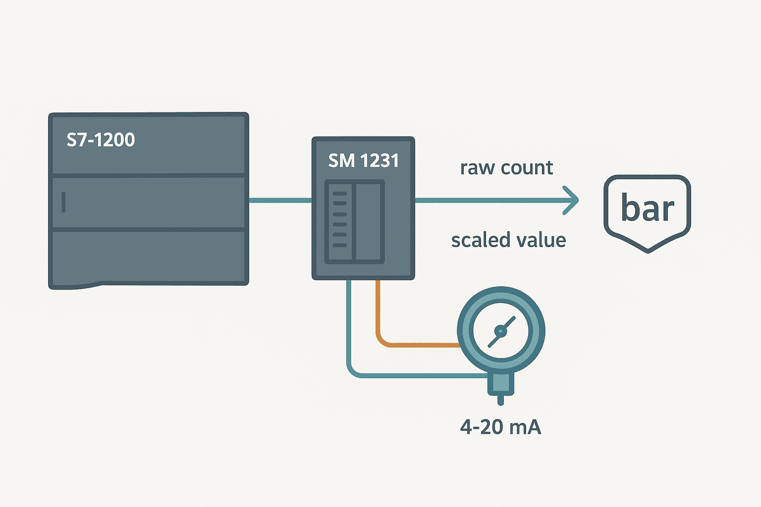
Getting an analog signal into an S7-1200 and seeing a sensible engineering unit value on screen sounds straightforward. In practice, three things trip people up every time: picking the wrong module for current signals, misreading the raw count range, and skipping the channel parameterization in TIA Portal hardware configuration. This guide fixes all three.
What Is an S7-1200 Analog Input?
An S7-1200 analog input converts a continuous process signal, typically 0-10 V or 4-20 mA, into a 16-bit signed integer that the CPU reads from the process image. The usable range for a 4-20 mA channel is 5530 to 27648 counts. The CPU stores this value at an IW address you assign during hardware configuration in TIA Portal, and your ladder or structured text code reads it from there.
Choosing the Right Hardware for Analog Inputs
The CPU 1214C and 1215C include two onboard analog inputs, but those are voltage-only, fixed at 0-10 V. If your transmitter outputs 4-20 mA, you need additional hardware. You have two paths:
- SB 1231 Signal Board (1 channel, mounts directly on the CPU faceplate, saves rail space, good for a single loop)
- SM 1231 Signal Module (4 or 8 channels, mounts on the expansion rail to the right of the CPU, configurable per channel for voltage or current)
On a water treatment project I commissioned in 2022, the panel builder had wired three 4-20 mA pressure transmitters to the onboard CPU inputs. The CPU 1214C happily reported values, but they were meaningless because the hardware only supports voltage. Swapping in an SM 1231 AI 4x13bit and reconfiguring took 40 minutes but saved days of head-scratching. Always check your CPU variant before wiring.
For a broader look at the CPU families before you commit to hardware, the S7-1200 vs S7-1500 comparison is worth reading.
Wiring a 4-20 mA Transmitter to the SM 1231
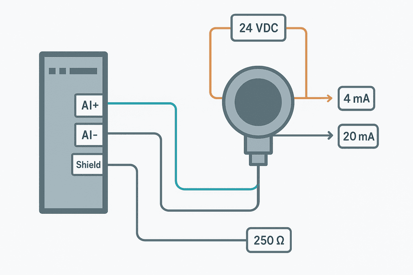
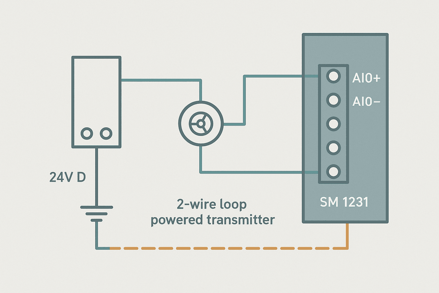
The SM 1231 terminal layout is printed on the module face. For channel 0 in current mode you use terminals 0+ and 0M. The module does not supply loop power, so you wire as follows:
- 24 VDC positive supply to transmitter positive terminal
- Transmitter signal output to SM 1231 terminal 0+ (AI 0+)
- SM 1231 terminal 0M (AI 0-) back to 24 VDC common (0 V)
- Short the M terminal to the panel chassis ground at one point only for shielded cable
For 4-wire (active) transmitters, the transmitter has its own power supply and you just connect the signal pair to AI 0+ and AI 0M. For 2-wire (passive/loop-powered) transmitters, you break the positive supply wire through the transmitter as described above. The PLC analog input wiring walkthrough has wiring diagrams for both types if you want a visual reference.
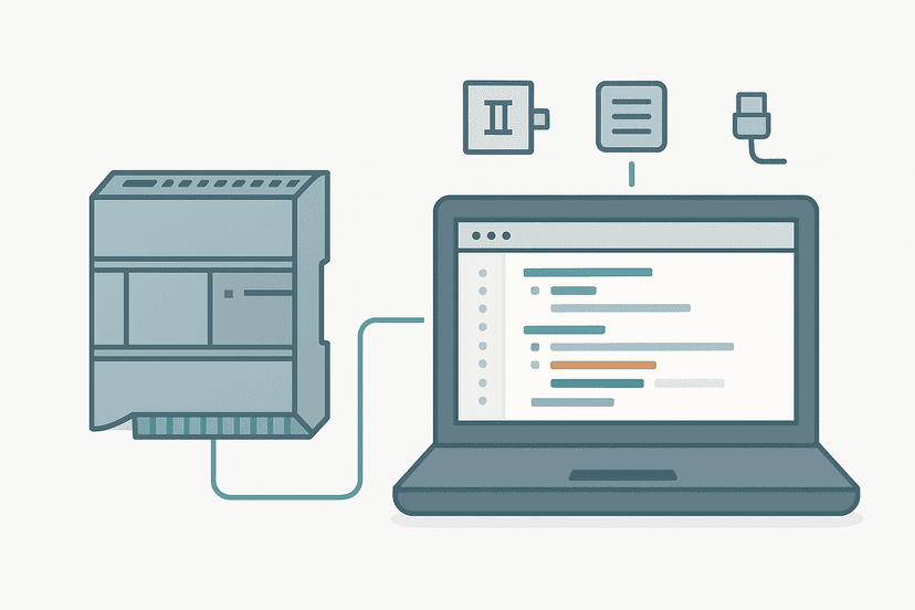
Configuring the Analog Channel in TIA Portal
Hardware configuration is where most beginners skip a step. The default channel type in TIA Portal is voltage. If you leave it there and wire current, you'll read wrong values and get no diagnostic fault because the hardware won't complain. Here's the correct sequence:
- Open your project in TIA Portal and go to Device Configuration.
- Click the SM 1231 module in the rack view.
- In the Properties pane, select the 'Inputs' tab.
- For each channel you are using, set 'Measurement type' to 'Current (4-wire transducer)' or 'Current (2-wire transducer)'. The 4-wire option disables wire-break detection; 2-wire enables it.
- Set the range to '4 mA to 20 mA'.
- Set 'Smoothing' to your preferred level. 'Weak' (4 samples) is a sensible starting point for most process signals.
- Note the start address in the 'I/O addresses' tab. This is your IW address, for example IW96 for channel 0 of the first SM 1231.
- Compile and download the hardware configuration.
Understanding the S7-1200 Analog Raw Count Range
This is the part that confuses engineers coming from other platforms. The S7-1200 does not simply map 4 mA to 0 and 20 mA to 32767. The full count table for a 4-20 mA channel is:
| Signal | Raw Count (INT) | Meaning |
|---|---|---|
| < 1.185 mA | < 0 | Wire break / underrange fault |
| 1.185 mA | -32768 (approx) | Severe underrange |
| 4 mA | 5530 | Minimum normal range |
| 12 mA | 16589 | Midscale |
| 20 mA | 27648 | Maximum normal range |
| > 22.8 mA | > 32511 | Overrange fault |
The key numbers to remember are 5530 and 27648. Your scaling formula always uses those as the raw low and raw high values. The 4-20 mA scaling formula guide explains the math behind this in detail.
Scaling the Raw Count to Engineering Units in Structured Text
TIA Portal offers NORM_X and SCALE_X instructions for this, but I prefer writing the linear formula directly in Structured Text. It's explicit, portable and easier for the next engineer to follow. Here's a working example for a 0-10 bar pressure transmitter:
// S7-1200 Analog Scaling: 4-20 mA to 0-10 bar
// Raw counts: 5530 = 4 mA (0 bar), 27648 = 20 mA (10 bar)

VAR
    PT101_RawINT    : INT;     // Read from IW96 via MOVE
    PT101_RawClamped : REAL;
    PT101_PressBar  : REAL;
    EU_Lo           : REAL := 0.0;     // 0 bar
    EU_Hi           : REAL := 10.0;   // 10 bar
    Raw_Lo          : REAL := 5530.0;
    Raw_Hi          : REAL := 27648.0;
END_VAR

// Clamp raw value to valid range before scaling
PT101_RawClamped := INT_TO_REAL(PT101_RawINT);
IF PT101_RawClamped < Raw_Lo THEN
    PT101_RawClamped := Raw_Lo;
END_IF;
IF PT101_RawClamped > Raw_Hi THEN
    PT101_RawClamped := Raw_Hi;
END_IF;

// Linear scaling
PT101_PressBar := EU_Lo + (EU_Hi - EU_Lo)
    * (PT101_RawClamped - Raw_Lo)
    / (Raw_Hi - Raw_Lo);
The clamping step before the formula is not optional. If you send an unclamped overrange value into the division, you get a pressure reading above 10 bar, which may trigger downstream logic incorrectly. Always clamp first. The Structured Text guide for TIA Portal covers more patterns like this if you want to build on it.
If you prefer a quick sanity check on your scaling math without writing code, the analog scaling calculator handles the 4-20 mA raw count conversion directly.
Reading the Analog Address in Ladder Logic (OB1)
If your project uses ladder rather than ST, you read the analog value with a MOVE instruction. Place a normally closed contact from a dummy always-true bit, then MOVE IW96 to a REAL or INT tag in your DB. From there, call a CALCULATE or FC block to do the scaling. Keep the raw read and the scaling in separate rungs so you can watch each step during online monitoring.
For online monitoring tips while commissioning analog channels, PLC troubleshooting with online monitoring shows exactly how to watch IW addresses live in TIA Portal without stopping the CPU.
Common Faults and How to Clear Them
Three faults come up on almost every commissioning job with S7-1200 analog inputs:
- IW reads 32767 constantly: Open-circuit or wire break. Check the transmitter is powered and the wiring is intact. In TIA Portal diagnostics, the channel will show 'Wire break' if configured for 2-wire current mode.
- IW reads a fixed low value around 5530 with no process variation: Channel is configured as voltage but wired for current, or transmitter output is not reaching the module. Verify channel type in device configuration.
- Noisy, jumping value: Ground loop from double-ended shield grounding, or signal cable running parallel to motor power cables. Separate the cable routes by at least 200 mm and ground the shield at one end only. See control panel wire routing best practices for cable segregation rules.
- Value correct at low end but saturates early: EU_Hi entered incorrectly in scaling code. Double-check your Raw_Hi constant is 27648, not 32767.
Smoothing and Filter Settings: What Actually Matters
TIA Portal offers four smoothing levels for SM 1231 channels: None, Weak (4 samples), Medium (32 samples) and Strong (64 samples). Each level averages more scans before presenting a new value, which reduces noise but adds latency.
For slow process variables like tank temperature or pressure, Medium or Strong is fine. For a flow signal feeding a PID loop with fast setpoint changes, stick with Weak or None, otherwise the filter introduces lag that destabilizes the loop. None of the filter levels cost you anything in terms of CPU load because the averaging happens inside the analog module hardware, not the CPU scan.
Connecting Analog Readings to an HMI
Once your scaled REAL value lives in a DB tag, linking it to an HMI display is a one-step tag connection in TIA Portal. The HMI tag linking guide explains exactly how to map DB variables to HMI tags so your pressure reading shows up correctly on the operator panel. And if you are building the HMI screens from scratch, HMI programming in TIA Portal covers the full workflow.
Keep Learning
Now that your analog input is wired, configured and scaling correctly, the natural next step is building your first complete S7-1200 program around it. Start with S7-1200 First Program in TIA Portal to see how a full OB1 structure fits together, then check the 4-20 mA scaling in PLC: ST and Ladder Code post for more scaling patterns across both languages. If you are planning to surface these values in a SCADA system, SCADA vs PLC: How They Work Together explains the architecture you are building toward.
Frequently asked questions
What raw count range does the S7-1200 analog input use for 4-20 mA?
How do I read an analog input address on the S7-1200 in TIA Portal?
Does the S7-1200 CPU 1214C have built-in analog inputs?
What is the difference between the SM 1231 and SB 1231 on the S7-1200?
Why does my S7-1200 analog input read 32511 or 32767?
How do I scale analog input raw counts to engineering units in TIA Portal Structured Text?
Can I use a 2-wire 4-20 mA transmitter with the S7-1200?
How do I enable wire-break detection on the S7-1200 analog input?
Learn this by building it
There is a PLC in this site. It runs a real scan engine, checks your logic against the same tests a working machine would fail, and needs no download and no account.
Open the exercisesFree, no signup, runs in your browser. See all 16 exercises.
Was this helpful?