PLC Output Wiring: Relay, Transistor and Triac
PLC output wiring causes more commissioning headaches than almost any other part of a control panel build. Not because it is complicated, but because the three main output types, relay, transistor and triac, each have rules that are easy to miss and failure modes that are expensive to learn the hard way. Get the wiring right once and you will rarely think about it again. Get it wrong and you will be replacing output modules on a live machine at 2 AM.
What Is PLC Output Wiring?
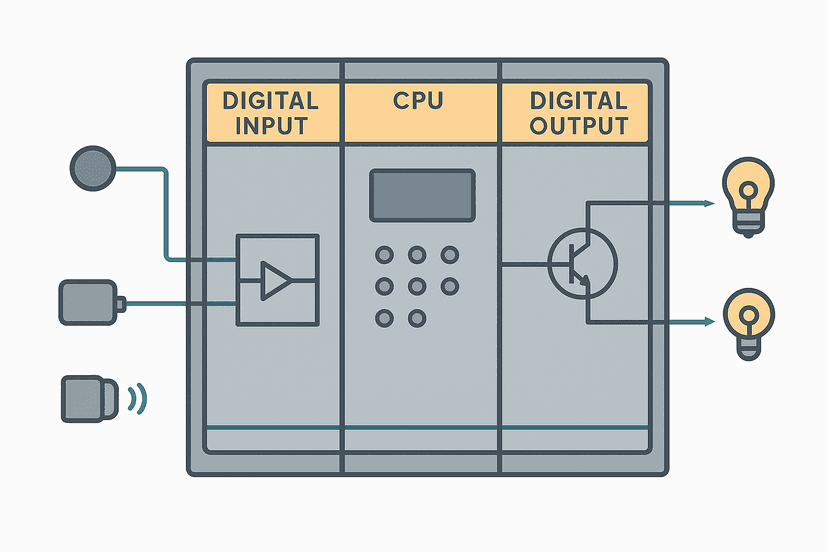
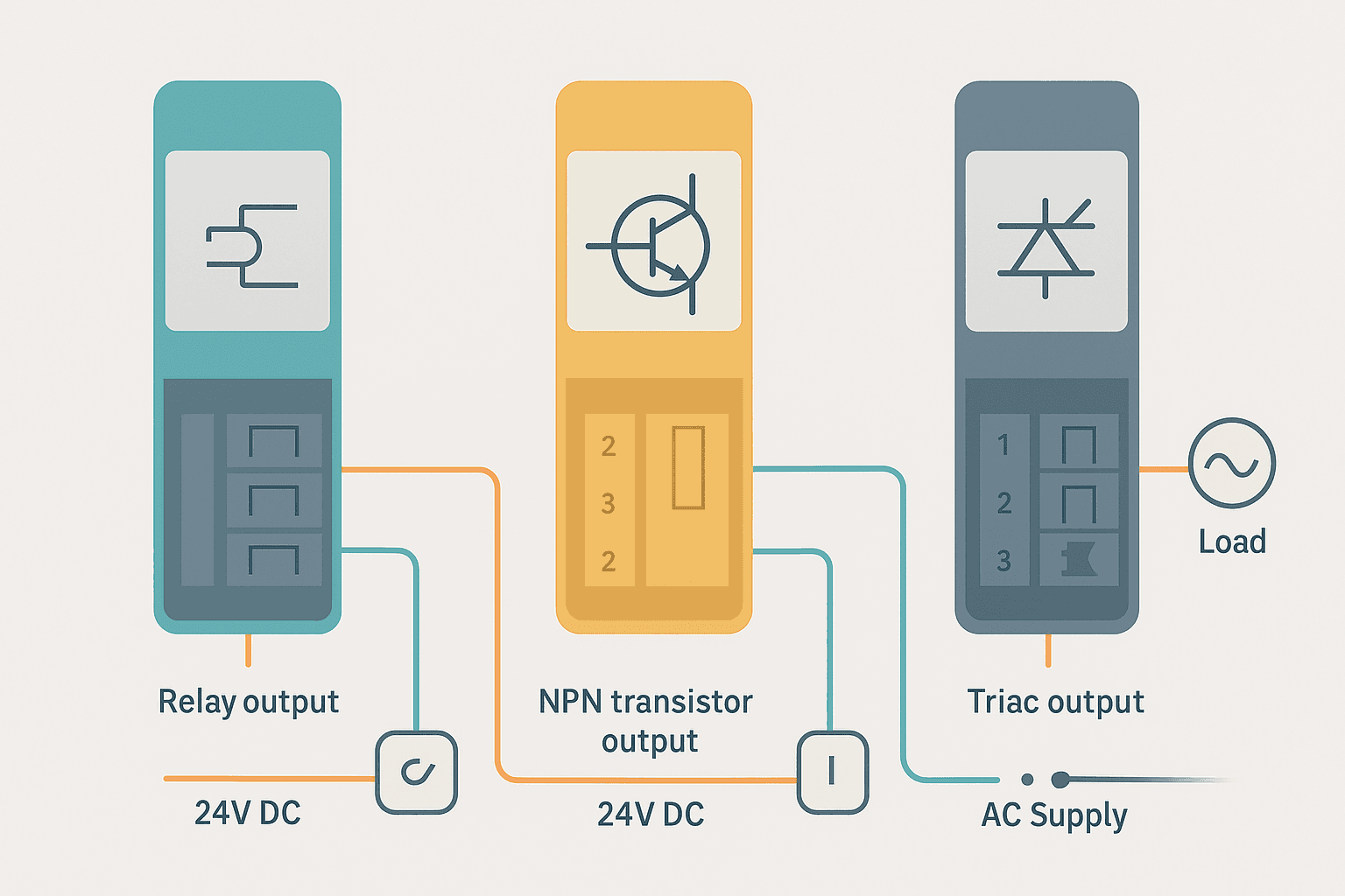
PLC output wiring is the process of connecting a PLC digital output module's terminals to field devices such as solenoid valves, contactors, pilot lights and relays so that the PLC can switch real-world loads. Each output module type, relay, transistor (BJT or FET), and triac, has a specific electrical character that determines which loads it can safely drive, how fast it can switch, and how it fails when pushed beyond its limits.
The Three PLC Output Types: What Each Actually Is
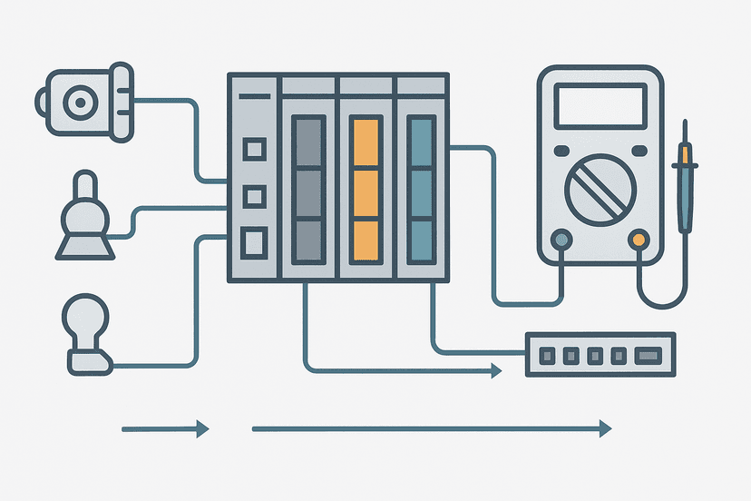
Before wiring anything, understand what you are working with. Understanding how PLC input and output modules work at the hardware level saves you from guessing.
| Output Type | Load Voltage | Max Switching Speed | Typical Current Rating | Best For |
|---|---|---|---|---|
| Relay | AC or DC, 5 to 250 VAC / 30 VDC typical | ~10 cycles/sec | 2 A per point | Infrequent switching, mixed voltage loads |
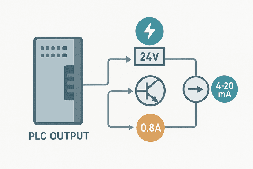
| Transistor (NPN/PNP) | DC only, 5 to 30 VDC | >1 kHz | 0.5 to 2 A per point | Fast switching, 24 VDC solenoids, PWM |
| Triac | AC only, 85 to 265 VAC | Zero-crossing, ~60 Hz | 0.5 to 1 A per point | Frequent AC switching, lamps, AC solenoids |
Relay Output Wiring: How to Do It Right
A relay output module contains a small electromechanical relay for each output point. When the PLC bit goes true, the relay coil energises and the contact closes. The contact is electrically isolated from the PLC logic circuit, which is the key advantage: you can switch 120 VAC, 240 VAC or 24 VDC loads from the same module.
The wiring is simple. Connect your load supply voltage to the common terminal (COM) for the output group. Connect the other side of the load to the individual output terminal (OUT). The load return goes back to the supply neutral or negative. That is the complete circuit.
The biggest enemy of relay outputs is inductive load switching without suppression. Every time a relay contact opens on a solenoid or contactor coil, the collapsing magnetic field produces a voltage spike. On an AC circuit, fit an RC snubber (typically 0.01 uF in series with 47 ohms) across the load terminals. On a DC circuit, fit a flyback diode (1N4007 or equivalent) across the coil with the cathode to positive. This is not optional. I have seen panels where relay output modules failed within weeks because the wiring team skipped suppression on eight solenoid outputs.
Relay contact life is typically rated at 100,000 to 300,000 operations under load. For outputs that switch more than a few times per minute, move to transistor or triac. The fuse and breaker selection guide covers how to protect relay outputs correctly with per-common fusing.
Transistor Output Wiring: DC Only, Polarity Matters
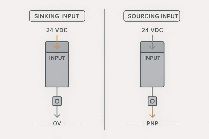
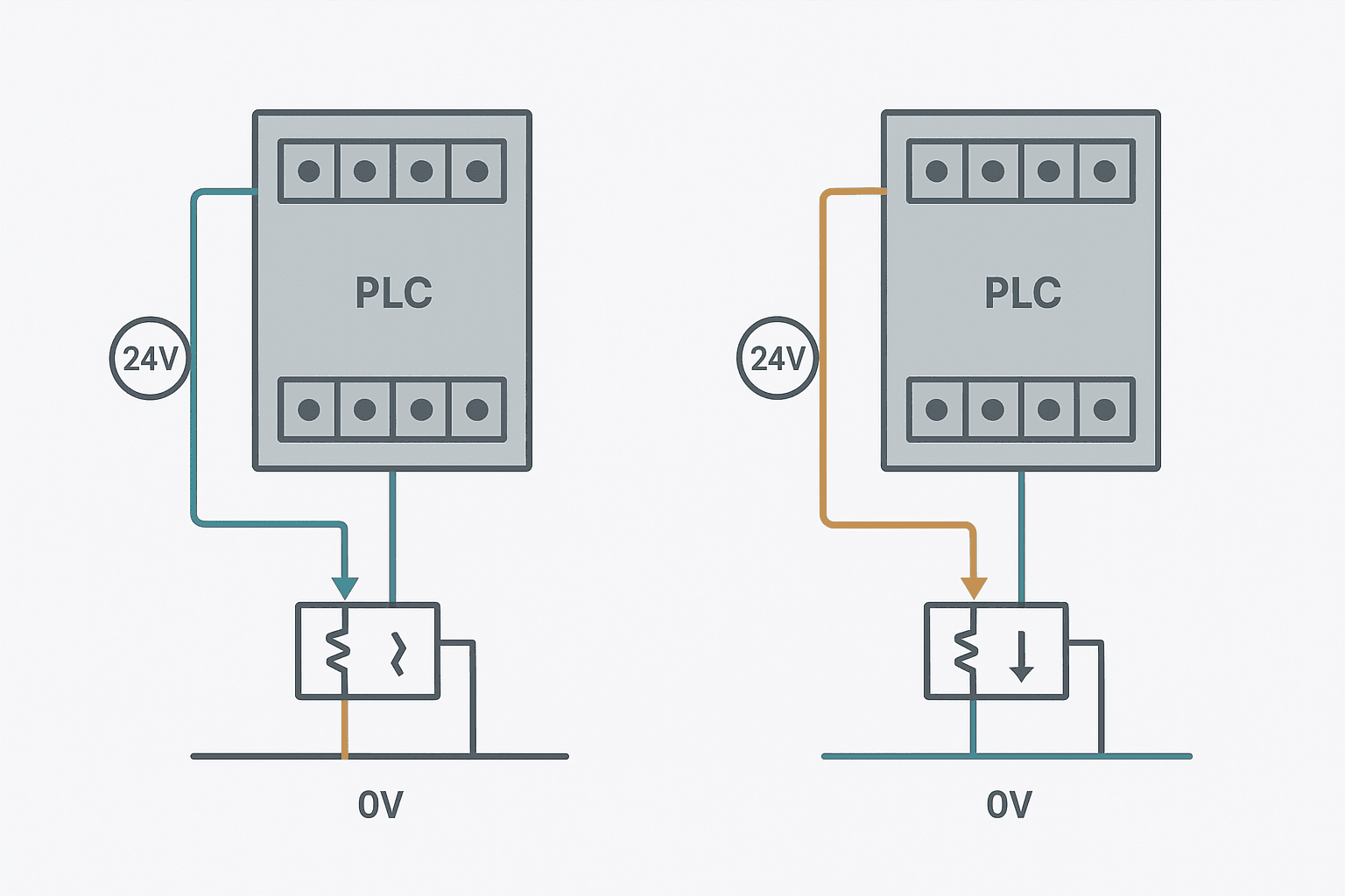
Transistor outputs are solid-state, DC only, and either sourcing (PNP) or sinking (NPN). This is the most common source of confusion when wiring them. Read the full breakdown at sinking vs sourcing PLC I/O if you need a refresher. Here is the practical wiring summary.
Sourcing (PNP) transistor output: The module pushes 24 VDC out through the output terminal when the bit is true. Wire the load between the output terminal and the 0 V (negative) rail. Current flows: 24 V supply to module, out of output terminal, through load, back to 0 V. The COM terminal on a sourcing module connects to 0 V.
Sinking (NPN) transistor output: The module provides a return path to 0 V. Wire the load between the 24 V supply and the output terminal. Current flows: 24 V supply, through load, into output terminal, through module to 0 V. The COM terminal on a sinking module connects to 0 V as well, but now it is the return path for the transistor.
Always connect the module's 24 VDC supply and 0 V terminals before wiring any outputs. Many modules have a separate logic supply and output power supply. Missing the output supply connection is a classic first-commission mistake: the PLC shows the bit energised but the output terminal reads 0 V.
Flyback diode placement on transistor outputs matters too. Place the diode as close to the load as possible, not at the module terminal. A diode at the module terminal leaves a long wire acting as an antenna for the spike before it is clamped. For pneumatic solenoid valve wiring, put the diode right at the solenoid connector.
Triac Output Wiring: AC Loads Done Right
Triac outputs are the solid-state equivalent for AC loads. The triac is a bidirectional semiconductor that conducts in both directions when triggered, which is exactly what you need for AC. When the PLC bit goes true, the triac fires at the next AC zero-crossing and the load sees full AC voltage.
Wiring a triac output is similar to a relay output but AC only. Connect the AC line to the COM terminal of the output group. Connect the output terminal to one side of the load. The other side of the load connects to AC neutral. Simple enough, but two things bite people.
- Leakage current: A triac always leaks a small current even when off, typically 1 to 10 mA. This is enough to keep a small indicator lamp dimly lit or cause a relay coil to chatter. If you see a load that refuses to turn fully off, leakage is the likely cause. The fix is to wire a bleeder resistor (typically 10 to 15 kohm, 2 W) in parallel with the load.
- Voltage drop: The triac drops roughly 1 to 2 V across itself when conducting. For most loads this is irrelevant, but for a tightly-tolerated load it can matter.
- No isolation: Unlike a relay, a triac output has no galvanic isolation between the AC load circuit and the PLC output circuit (beyond an optocoupler). Do not assume triac outputs are as isolated as relay outputs for safety purposes.
Output Common Wiring and Grouping
Most PLC output modules group multiple output points onto shared common terminals. The Siemens S7-1200 SM 1222 DC output module, for example, groups 8 or 16 outputs onto a single 24 VDC common. Rockwell 1769 and 1734 modules similarly group 4 to 8 points per common. Why does this matter?
When you share a common, all outputs in that group must use the same supply voltage and polarity. If you need to drive a mix of 24 VDC solenoids and 120 VAC pilot lights, they must go to different groups with different commons. Mix them on the same common and you will either damage the module or create a safety hazard.
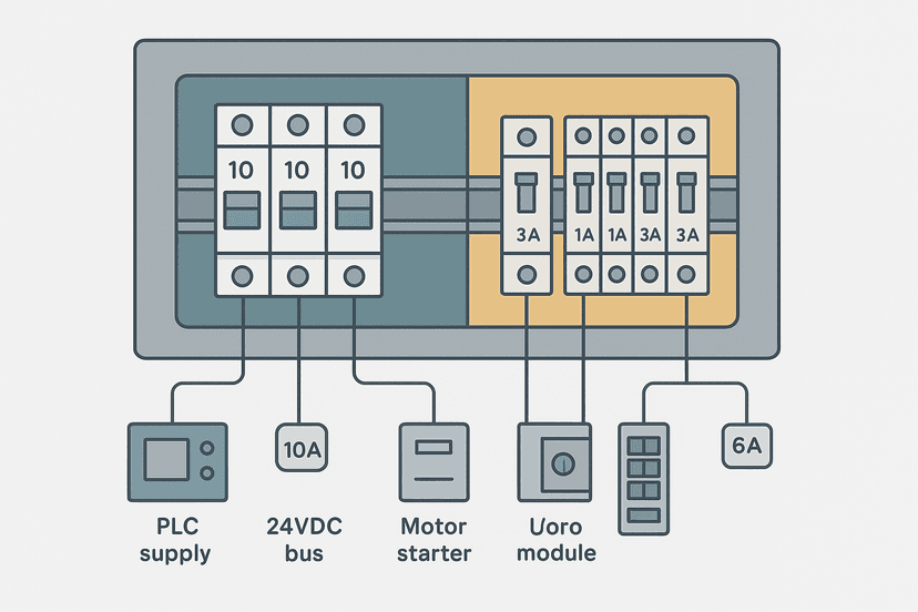
Fuse each common separately. The module's per-common current limit is real. A short on one output can pull the whole common down if there is no fuse. For safety-critical outputs such as an emergency stop circuit, the output wiring and protection scheme must be treated with extra care. Do not share a safety relay drive output on the same common as a general-purpose solenoid.
Wire Sizing and Routing for Output Circuits
Most 24 VDC PLC output circuits run at 0.5 A or less per point. 0.75 mm2 (18 AWG) is adequate for runs up to about 10 m in a control panel. For longer field cable runs, voltage drop becomes the calculation to make, not just ampacity. A 24 VDC solenoid that sees only 20 V because of undersized cable may not reliably actuate.
Keep output wiring away from input signal wiring. AC output cables especially should not run alongside 4-20 mA analog signal cables. The wire routing and segregation guide covers the trunking rules in detail. For analog output wiring specifically, the PLC analog output wiring guide covers the shielding and grounding rules that digital output wiring does not need.
How Output Modules Fail and How to Spot It Fast
Relay outputs fail in two ways: open (contact welds apart, output always off) or shorted/welded (contact sticks closed, output always on). Transistor outputs typically fail shorted (output always on) when the transistor is destroyed by a voltage spike or overcurrent. Triac outputs fail shorted too, which is why a triac output failure can be more hazardous than a relay failure: the load stays energised.
The PLC I/O fault diagnosis guide has step-by-step multimeter procedures. The quick test: force the output bit off in the PLC and measure voltage at the output terminal. If you still read supply voltage on a transistor output, the transistor is shorted. On a relay, measure resistance across the contact with power off: zero ohms with the coil de-energised means a welded contact.
The PLC power supply faults guide is worth reading alongside this: an overloaded 24 VDC supply caused by too many output loads will cause outputs to drop out intermittently in ways that look like output module faults but are actually a supply sizing problem. The 24 VDC power supply sizing guide explains exactly how to budget the output load current.
Choosing the Right Output Type for Your Load
- 24 VDC solenoid valve, infrequent switching (less than 10 cycles/min): relay output with flyback diode at the load
- 24 VDC solenoid valve, frequent switching or PWM: transistor output (sourcing or sinking to match your sensor commons) with flyback diode
- 120/240 VAC solenoid or AC contactor coil, infrequent switching: relay output with RC snubber
- 120/240 VAC lamp or AC solenoid, frequent cycling: triac output, add bleeder resistor if load is small
- High inrush load (motor contactor, transformer primary): relay output sized with enough surge margin, or interposing relay from transistor output
- Safety relay coil drive: check the safety relay's input voltage spec, then wire through a dedicated relay output point with its own fused common, and review safety relay wiring
Keep Learning
Now that you have the output wiring fundamentals solid, the next step is understanding what happens when outputs misbehave in service. The PLC output fault diagnosis guide walks you through every failure mode with real test procedures. If you are also setting up input wiring, the PLC digital input faults guide covers the input side the same way. And for the full picture of how the module sits inside the rack, how PLC input and output modules work is a good companion read.
Frequently asked questions
What is the difference between relay and transistor PLC outputs?
Can I use a transistor PLC output to drive an AC load?
Why does my relay PLC output fail faster than expected?
What does a triac PLC output do that a relay cannot?
How do I know if my PLC output module is sinking or sourcing?
What fuse size should I use on a PLC output?
Can I drive a 24 VDC contactor coil directly from a PLC transistor output?
Why does my PLC output stay on even after the coil bit goes to zero?
Do I need a suppression diode on every DC output driving a solenoid?
What is the common terminal on a PLC output module?
Learn this by building it
There is a PLC in this site. It runs a real scan engine, checks your logic against the same tests a working machine would fail, and needs no download and no account.
Open the exercisesFree, no signup, runs in your browser. See all 16 exercises.
Was this helpful?