PLC Panel Electrical Noise: Causes and Fixes
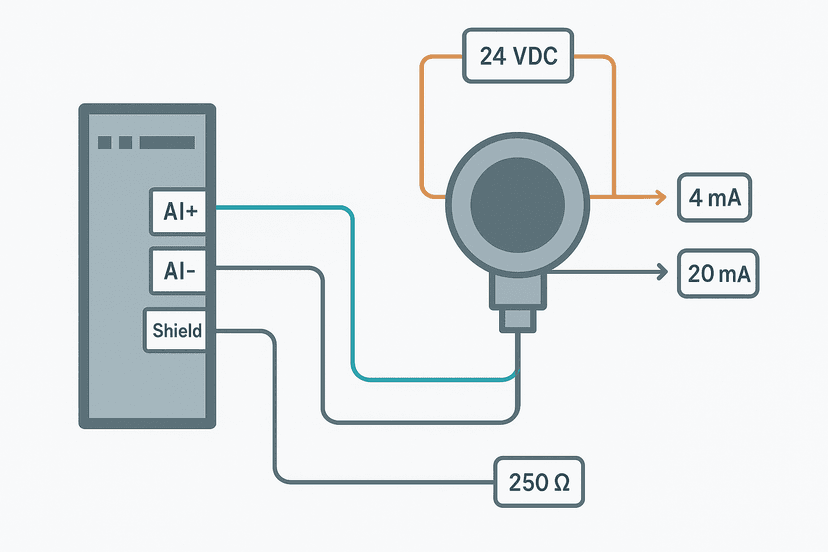
You have a sensor that is definitely not moving, but the PLC input bit is flickering on and off. Or your 4-20 mA pressure transmitter reads steady on the field instrument but shows ±300 counts of jitter in the PLC. Or a communication fault keeps dropping out every time a large motor starts. In every one of these cases, electrical noise is the likely cause. And in my experience, it is one of the most misdiagnosed problems in panel commissioning because people assume wiring problems mean wiring faults, not interference.
What Is Electrical Noise in a PLC Panel?
Electrical noise in a PLC panel is unwanted electrical energy that couples onto signal wiring or power rails, causing the PLC to read incorrect values or behave erratically. It arrives by three routes: conducted (along shared wiring), capacitively coupled (between cables running in parallel), or inductively coupled (from switching magnetic fields). The result is false input triggers, drifting analog readings, and corrupted communication data, none of which has anything to do with a broken field device.
The Main Sources of Electrical Noise in Control Panels
Before you can fix noise you need to know where it is coming from. There are four culprits that account for the vast majority of noise complaints.
Variable Frequency Drives
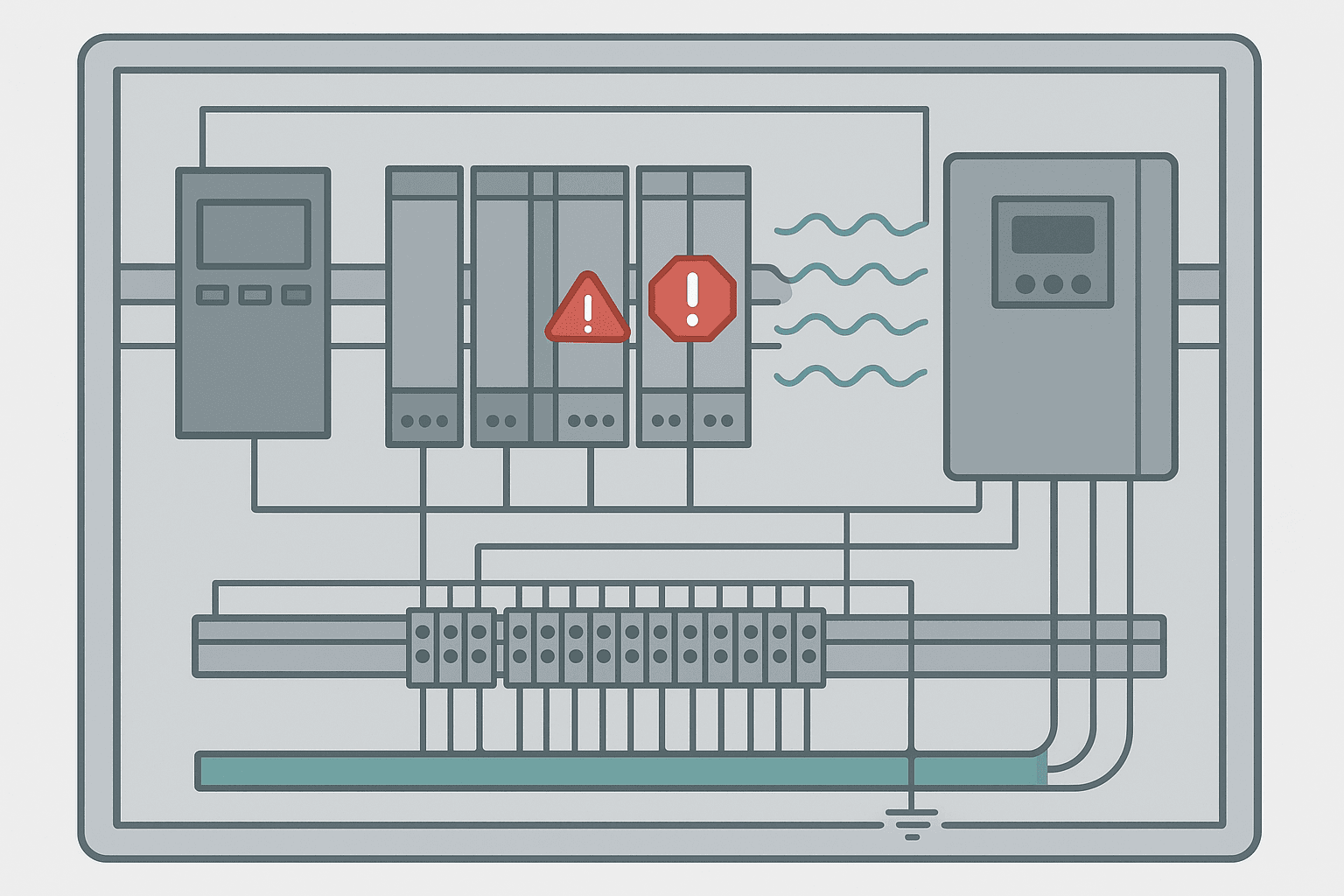
VFDs are probably the single most common noise source on a modern plant floor. They switch at carrier frequencies between 2 kHz and 16 kHz using IGBT transistors, and that switching generates high-frequency voltage spikes on both the motor cable and the drive's power supply cable. The motor cable acts like an antenna. If it runs in the same cable duct as your PLC signal wiring, those spikes couple directly onto your analog inputs. I have seen a 4-20 mA level signal jump from 12.0 mA to 14.8 mA the instant a 15 kW VFD was enabled, purely from capacitive coupling through a shared cable tray. The fix involved rerouting the motor cable and fitting an output line reactor on the VFD. If you are dealing with VFD fault codes alongside signal noise, suspect the drive immediately.
Inductive Kickback from Solenoids and Relay Coils
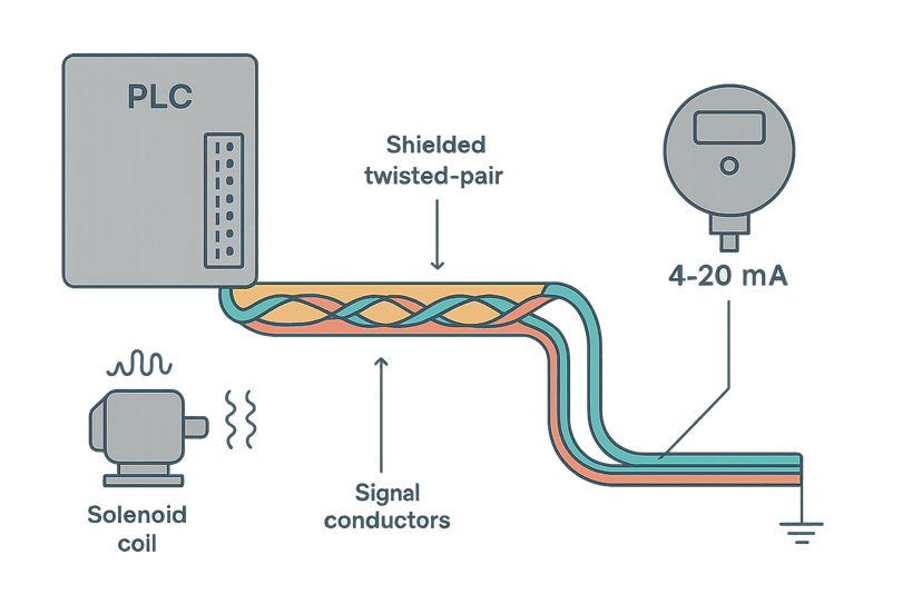
Every inductive coil, solenoid valve, contactor or relay stores energy in its magnetic field. When the PLC output switches it off, that energy has to go somewhere. Without a suppression device, it creates a voltage spike that can reach 10 to 20 times the supply voltage for a few microseconds. On a 24 VDC system that is 240 to 480 V on the output wiring. That spike travels back into the output module and can also couple onto adjacent signal wires in the same duct. This is a particularly nasty source because it is synchronised with your own PLC outputs, so it can be very hard to spot. Always fit a flyback diode directly across DC coils, rated at the supply voltage with a current rating equal to the coil current. For AC coils, a MOV or RC snubber across the coil is the standard approach. Wire the suppressor directly at the load, not back at the PLC terminal.
Poor Panel Grounding
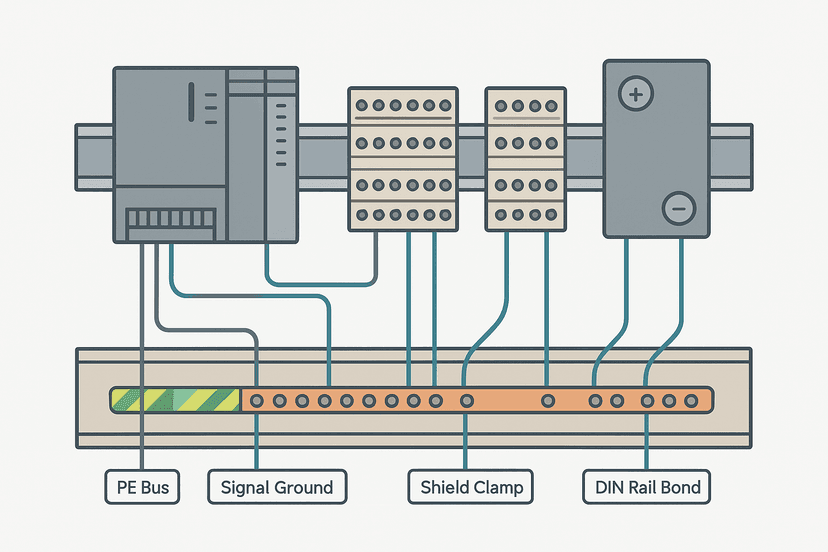
A noisy ground reference is one of the most insidious problems because it affects everything simultaneously. If your 24 VDC negative rail, your instrument earth and your protective earth are all bonded at different points with different impedances, you end up with circulating currents on the ground conductors. Those currents shift the reference voltage that your analog inputs measure against, which reads as noise. Proper control panel grounding means a single-point star ground or a proper grounding bus bar with short, low-impedance connections to each sub-system. If you have not read the detail on this already, the fundamentals are worth revisiting.
Cable Routing and Segregation
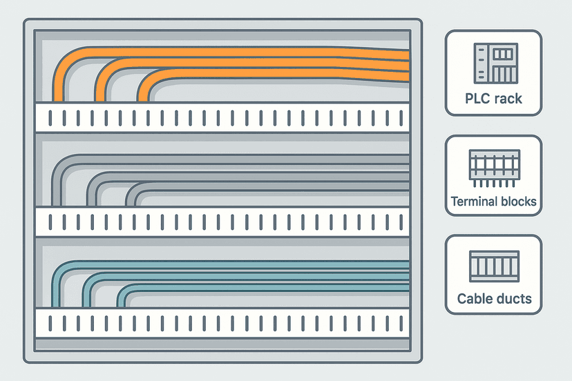
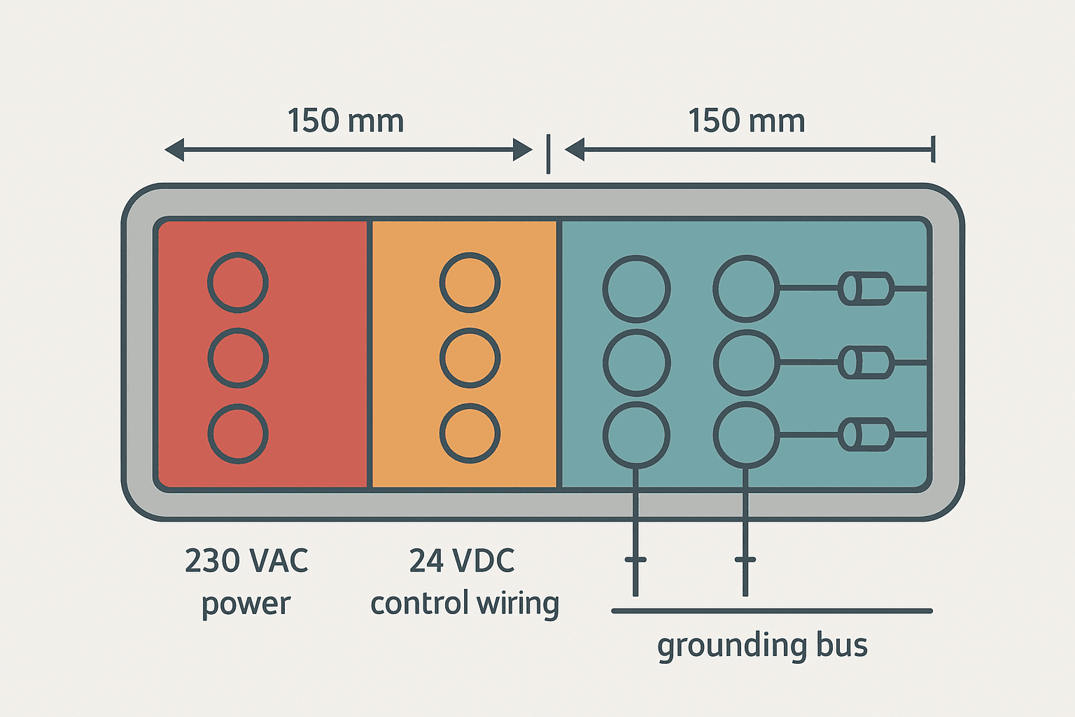
Running 230 VAC power wiring in the same duct as 24 VDC sensor cables is a classic commissioning shortcut that creates long-term problems. The capacitance between parallel conductors couples AC voltage onto the low-level signal. Even 100 mm of parallel run at 230 VAC can inject enough current into a high-impedance analog input to shift the reading. Detailed guidance on control panel wire routing and segregation covers the specific rules, but the headline is: power, control and signal cables belong in separate ducts with physical separation.
How Electrical Noise Gets Into Analog Signals
Analog signals deserve special attention because they are low-level and high-impedance. A 4-20 mA loop is more noise-immune than a 0-10 V signal because the current signal is relatively insensitive to voltage noise picked up in the cable. But even 4-20 mA loops suffer when noise currents are large enough or the loop impedance is high. A 0-10 V input with 100 kΩ input impedance can shift by hundreds of millivolts from capacitively coupled noise on a shared cable run, which translates directly to a reading error. The posts on PLC analog input wiring and 4-20 mA scaling assume a clean signal arriving at the module. If the raw count is jumping around, the scaling formula is not the problem.
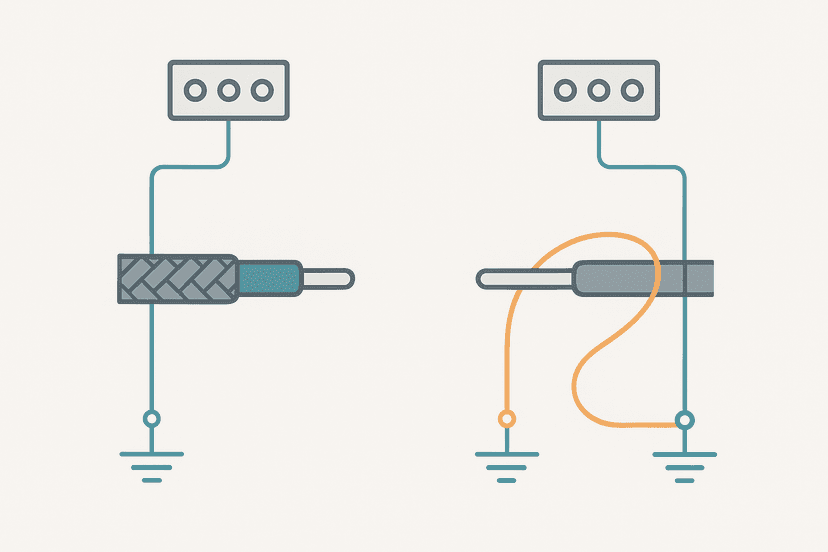
For analog cables, shielded twisted pair is the standard. The twist rejects differential magnetic noise. The shield rejects capacitively coupled electric field noise. But the shield only works if it is grounded correctly. Ground it at the panel end only, to the instrument earth bus. If you ground both ends you create a ground loop: any potential difference between the two earth points drives a current through the shield, and that current induces noise into the conductors inside. The topic of cable shield grounding and shielding analog signal cables are covered separately in this cluster and are worth reading alongside this one.
Diagnosing Electrical Noise Step by Step
Noise problems are often intermittent, appearing only when a particular machine is running. That makes them tricky. Here is the diagnostic sequence that actually works.
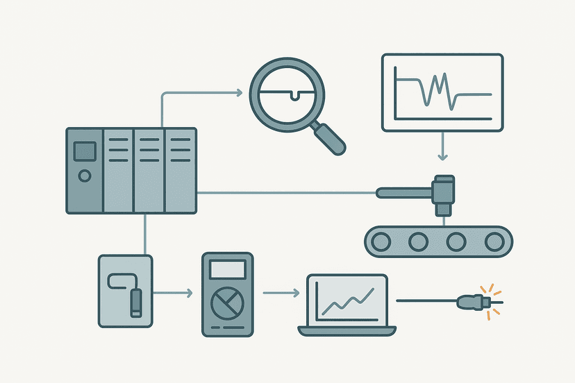
- Confirm the symptom in online monitoring. Watch the raw input value or bit state in the PLC while the field device is known-stationary. If it moves, you have a real noise problem. Use PLC troubleshooting with online monitoring to capture the timing.
- Isolate the wiring. Disconnect the field cable at the PLC input terminal. If the noise disappears, it is coming in through the cable. If it persists, the module itself is the issue (rare but possible).
- Correlate with machine events. Does the noise appear only when a specific VFD, contactor or solenoid is energised? Use a data trend on the HMI or a scope on the input terminal to time-correlate. This narrows the source fast.
- Check cable routing. Trace the suspect cable physically. Does it run alongside a motor cable or 230 VAC supply for more than 300 mm? That is your coupling path.
- Measure ground potential. With a multimeter, measure AC voltage between your instrument earth bus and the panel earth bar. More than 1 V AC suggests a ground current problem. Use the method in how to find a ground fault as a starting point.
- Check suppression on inductive loads. Look for a flyback diode or MOV on every solenoid and relay coil driven by the affected circuit. Missing suppressors are a fast win.
- Verify shield termination. Is the shield grounded? Where? Both ends means a ground loop. Fix to panel end only.
Practical Fixes and Their Priority
| Fix | Targets | Cost/Effort | Typical Effectiveness |
|---|---|---|---|
| Fit flyback diodes / MOVs on all inductive coils | Kickback spikes on outputs and adjacent signal wires | Very low | High for output-coupled noise |
| Separate motor cables from signal cables (min 150 mm) | VFD radiated noise on analog and digital inputs | Low to medium (rerouting) | High |
| Use shielded twisted pair, grounded at panel end only | Capacitive and magnetic coupling on analog signals | Low (cable cost) | High for analog loops |
| Add VFD output line reactor or dV/dt filter | VFD switching noise at source | Medium | High for VFD-heavy panels |
| Star-point or low-impedance instrument earth bus | Ground loop and common-mode noise on all signals | Low to medium | High, especially for analog |
| Install ferrite cores on sensor cables at panel entry | High-frequency conducted noise from field wiring | Very low | Moderate for HF noise |
Noise on Digital Inputs: A Special Case
Digital inputs have defined voltage thresholds, so they are inherently more noise-immune than analog signals. A 24 VDC input module typically has a minimum ON threshold around 15 V and a maximum OFF threshold around 5 V. But noise spikes can still exceed those thresholds for microseconds, long enough for the module to register a false transition. This is especially true for high-impedance inputs where a 10 nF cable capacitance can deliver a 15 V spike from a 150 V kickback transient in about 1 microsecond.
If you are seeing intermittent sensor faults or flickering digital input bits, and the sensor wiring checks out physically, noise is the next suspect. Most modern PLC input modules have a configurable input filter time, usually settable from 0.1 ms to 20 ms. Increasing this from the default (often 1 ms) to 5 ms or 10 ms eliminates most noise-induced false triggers with no impact on normal sensor response time. Check your module documentation, because on an S7-1200 this is set per channel in TIA Portal hardware configuration, and on a ControlLogix or Compact GuardLogix module it is done in the connection properties. You will not find this in the ladder logic itself. Separately, review PLC digital input faults for the full diagnostic process on input module problems.
Noise on Communication Networks
EtherNet/IP and PROFINET are differential signals running at 100 Mbit/s, and they have built-in error checking. But high noise levels, particularly from VFDs, can still cause retransmissions and ultimately connection timeouts. If you are getting PROFINET communication loss or EtherNet/IP communication loss that correlates with drive activity, check that your Ethernet cables are Cat5e or Cat6 with continuous foil shield, and that the shield is terminated at both ends through the connector shell. Industrial M12 or RJ45 panel connectors with proper backshell grounding make a real difference here.
For serial protocols like Modbus RTU on RS-485, the differential nature of the bus gives good noise rejection, but only if the cable is properly terminated with 120 Ohm resistors at both ends and the common (signal ground) wire is connected. A missing terminator raises the noise susceptibility dramatically and causes CRC errors. The Modbus RTU protocol wiring guide covers termination in detail.
From the Field: A Real Noise Diagnosis
On a food processing line I commissioned a few years back, we had a Siemens S7-1200 with a 4-channel analog input module reading four pressure transmitters. Three channels were rock solid. The fourth was jumping by plus or minus 400 raw counts (about 1.5% of full scale) at completely random intervals. The transmitter itself was fine: a handheld calibrator on the loop showed no variation.
Tracing the cable back through the panel, the fourth transmitter cable was the shortest run and had been cable-tied to a 22 kW VFD output cable for about 600 mm inside the main cable duct. We rerouted the transmitter cable to the opposite side of the duct with a 200 mm air gap and the noise disappeared immediately. Total fix time: 20 minutes. The lesson: always check which analog channel is noisy and trace its cable first. It is almost never the module.
Keep Learning
If this post has helped you track down a noise problem, the next step is getting the grounding and shielding fundamentals locked down so the issue does not come back. Start with Control Panel Grounding: The Right Way to Do It for the earth bus and bonding details, then read Cable Shield Grounding: One End or Both? for the specifics on shield termination. If your analog readings are still behaving oddly after fixing the noise, the 4-20 mA Scaling Formula guide will confirm whether the raw count range is correct.
Frequently asked questions
What causes electrical noise in a PLC panel?
How do I know if my PLC input is flickering because of noise?
Does a VFD cause noise in PLC panels?
What is the difference between common-mode noise and differential noise in instrumentation?
Should I add a suppressor across every solenoid and relay coil in a PLC panel?
Can electrical noise damage a PLC?
How far should I separate signal cables from power cables in a control panel?
What is the correct way to ground a cable shield in a PLC panel?
Does using shielded cable fix all electrical noise problems?
Can Modbus RTU or other serial communications be affected by panel noise?
Now build it
You have just read about MOV. Reading a rung and making one behave are different skills, and the second one is the job.
Mode (Auto / Manual)
Intermediateabout 15 minTwo mutually exclusive mode coils selected by momentary buttons: the skeleton behind every Auto/Manual selector. Each mode seals itself in, and pressing the other button switches over cleanly.
Build this rungFree, no signup, runs in your browser. See all 16 exercises.
Was this helpful?