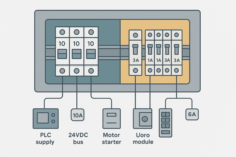
DIN Rail Terminal Blocks: Wiring and Selection Guide
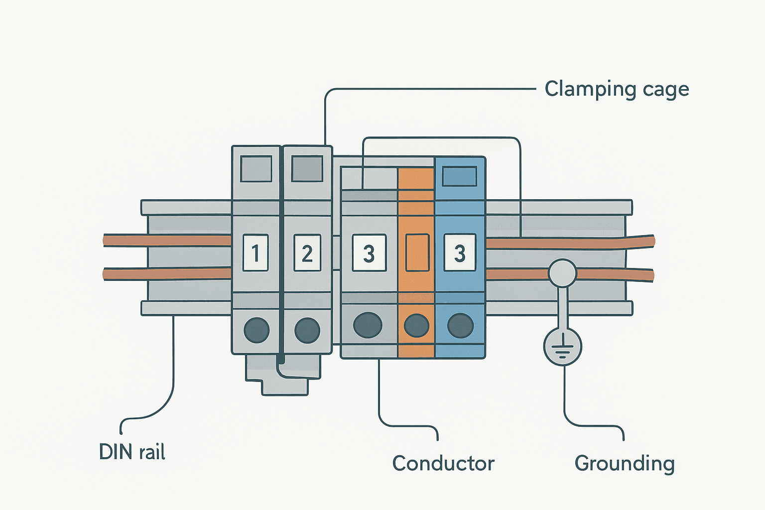
Every PLC panel has them, but terminal blocks rarely get the attention they deserve until something fails. A loose screw, an undersized block, a missing jumper bar, or a conductor stripped too short can cause intermittent faults that take hours to trace. Getting terminal block selection and wiring right from the start saves that pain entirely.
What Are DIN Rail Terminal Blocks?
DIN rail terminal blocks are modular, snap-on connectors that mount onto a standard 35 mm DIN rail (defined in IEC 60715) and provide a secure, individually accessible connection point between field wiring and panel wiring. Each block contains an internal metallic clamping cage that grips a stripped conductor and connects it electrically to the conductor entering from the opposite side. Blocks are arranged in rows, separated by insulating barriers, and can be grouped with jumper bars, end stops and label carriers to form a complete marshalling system.
Types of DIN Rail Terminal Blocks
There are four main connection technologies you will encounter on any project.
- Screw clamp (cage clamp): A screw presses a clamping cage onto the conductor. Reliable, widely understood, and cheap. Requires correct torque and re-tightening after the first thermal cycle on new panels.
- Spring clamp (push-in or lever): A permanent spring holds the conductor. Vibration-proof, faster to wire, no torque wrench needed. Wago 221 and Phoenix Contact Pushin series are the best-known examples.
- Bolt clamp: Used for larger conductors (16 mm² and above) where a bolt directly clamps the conductor lug. Common on power distribution terminals.
- Insulation displacement (IDC): The conductor is pushed onto a sharp blade that cuts through insulation. Used mostly in data and signal wiring, not common in PLC power circuits.
On a typical PLC panel I built for a water treatment site, we used spring-clamp terminals throughout the marshalling section because the panel was next to a pump set and vibration was a real concern. Screw terminals in that environment need re-torquing after six months; spring-clamp types simply do not. The extra cost per terminal was negligible against one call-out.
DIN Rail Terminal Block Sizes and Wire Ranges
Terminal blocks are rated by the maximum conductor cross-section they accept, not the current they can carry continuously, though the two are related. Choosing the right size means matching both the conductor size and the continuous current rating. The table below shows common sizes from Phoenix Contact (UT series) and Wago (281 or 2016 series), which are representative of the market.
| Rating | Conductor Range | Continuous Current | Typical Pitch | Common Use |
|---|---|---|---|---|
| 1.5 mm² | 0.14 to 1.5 mm² | 17.5 A | 5 mm | 24 V signal, sensor wiring |
| 2.5 mm² | 0.2 to 4 mm² | 24 A | 6 mm | PLC I/O, 24 V power rails |
| 4 mm² | 0.2 to 6 mm² | 32 A | 6 to 8 mm | 115/230 V control circuits |
| 6 mm² | 0.2 to 10 mm² | 41 A | 8 mm | Motor starter control |
| 10 mm² | 1 to 16 mm² | 57 A | 10 mm | Power distribution bars |
| 16 mm² | 6 to 25 mm² | 76 A | 12 mm | Main power incoming |
For most PLC digital I/O wiring using 0.75 mm² or 1 mm² stranded cable, a 2.5 mm² terminal block is the standard choice. It gives you plenty of headroom and uses the most common pitch, so accessories like jumper bars and end clamps are readily available. For 4-20 mA analog signal wiring, the same 2.5 mm² block works fine, but you might want a shield termination block nearby for the cable screen.
Torque Specifications: The Number Most People Skip
Under-torqued screws are one of the most common causes of intermittent faults in a control panel. The conductor is not fully clamped, so resistance at the joint increases with temperature, which increases temperature further, which loosens the joint over time. You end up with a warm terminal block and an input that drops out randomly. If you have ever chased one of those, you know how frustrating it is.
Over-torquing cracks the plastic housing or deforms the clamping cage, which can actually reduce the clamping force. You cannot always see the damage visually. If you have overtightened a terminal, replace it. They are cheap.
How to Wire DIN Rail Terminal Blocks Correctly
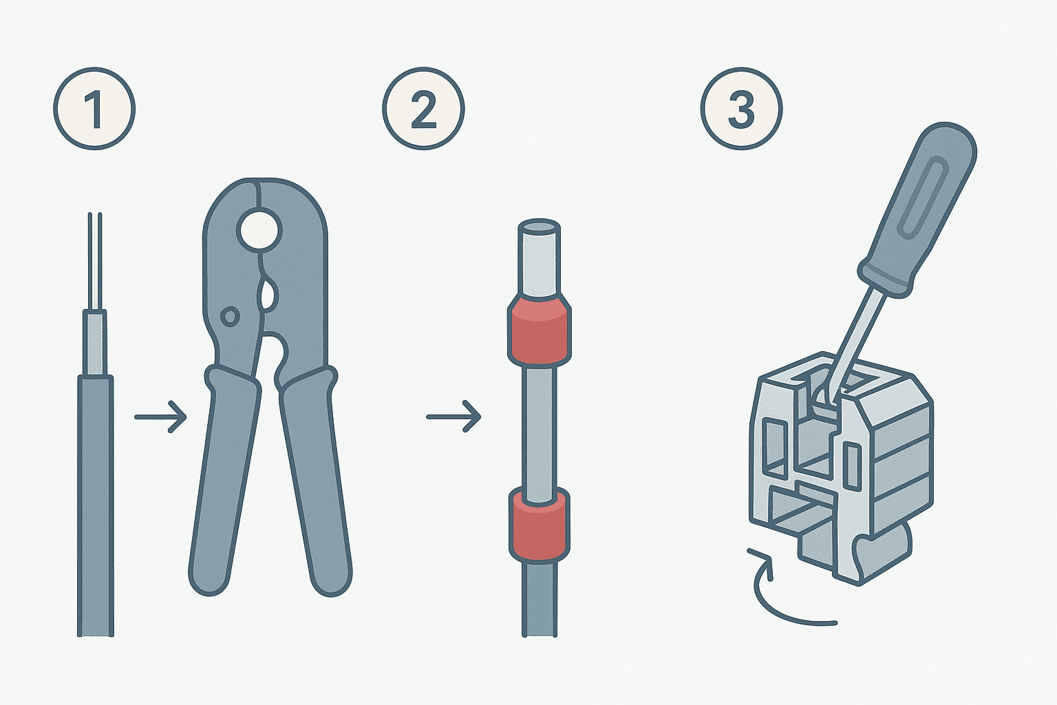
Correct wiring is straightforward once you follow a consistent process. Here is what I use on every build.
- Strip to the correct length. The datasheet specifies a stripping length, typically 7 to 10 mm for screw terminals, 8 to 12 mm for spring-clamp. Too short and the clamp grips insulation; too long and bare conductor is exposed outside the housing.
- Use ferrules on stranded wire. Always fit a crimped ferrule to stranded conductors before inserting into a screw terminal. This prevents individual strands from escaping the cage and causing shorts. Ferrule sizes are colour-coded: red for 1 mm², black for 1.5 mm², grey for 2.5 mm². Wago and Phoenix Contact spring terminals accept fine-stranded wire without ferrules, but ferrules still improve long-term reliability.
- Insert straight, push fully home. The conductor must reach the back of the cage. A common mistake is stopping short, which leaves the conductor gripped only by the tip of the cage.
- Tighten to torque spec (screw type) or confirm the spring has snapped shut (spring type). Give the conductor a firm tug after insertion. It should not move.
- Dress the cable and label immediately. Apply wire markers at both ends before moving to the next terminal. You will not remember which wire goes where after 80 terminals.
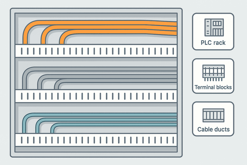
The control panel wire routing and segregation guide covers how to organise the wiring duct side of things, but terminal block discipline is what ties it all together at the connection point.
Using Jumper Bars to Distribute Common Rails
A jumper bar (also called a bridge or comb jumper) is a multi-position metal comb that clips into the test-point slots on the top of adjacent terminal blocks, shorting them together. This is the correct way to create a common 24 V supply rail or a 0 V common across a group of terminals without daisy-chaining individual wires from one screw to the next.
Jumper bars come in fixed lengths (2, 3, 5, 10 positions) and in breakable strips that you snap to the exact count needed. Phoenix Contact sells them as "FBS" series; Wago calls them "jumper links". The pitch of the jumper must match the pitch of the terminal block exactly, so a 6 mm pitch bar will not fit an 8 mm pitch terminal.
Grounding and PE Terminals
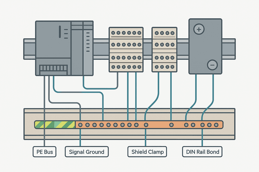
Green-yellow PE (protective earth) terminals are a distinct type. They connect directly to the DIN rail, which must itself be bonded to the panel earth bar. Every time you have a cable screen, a motor frame earth, or a sensor body earth to terminate, it should land on a PE terminal, not a standard grey terminal connected to a separate green wire. Using the wrong terminal type here is a real inspection failure and a safety issue.
The control panel grounding guide goes deeper on panel bonding, but the principle at the terminal block level is simple: PE terminals are conductive to the rail, standard terminals are insulated from it. Do not mix them up.
Specialist Terminal Block Types Worth Knowing
- Fused terminal blocks: Built-in fuse holder in the current path. Use them to protect individual PLC output circuits feeding solenoid valves or other inductive loads. See the fuse and breaker selection guide for sizing.
- Disconnect terminal blocks: A rotary or knife-type disconnect allows the circuit to be isolated at the terminal without removing wires. Useful for field device maintenance.
- Test and disconnect (TD) terminals: Combine a test point, a bridge jumper slot, and a knife disconnect in one body. Standard on many European machine builds.
- Sensor terminal blocks: Four-level versions that let you bring in a 24 V supply, connect it to the sensor, and take the sensor signal output on a single terminal body. Reduces terminal count for three-wire PNP/NPN sensors significantly.
- Shield termination terminals: Accept a cable screen and connect it to the rail (and therefore to PE). Essential for analog signal cables and anything where you are dealing with cable shield grounding.
Labelling and Documentation
A terminal block with no label is almost useless during fault-finding. Every terminal should carry a wire number that matches the electrical drawing. Both ends of every wire should be marked: at the terminal block and at the device it connects to. Most panel builders use heat-shrink printed markers or snap-in label carriers (Phoenix Contact Zack markers or equivalent).
Section markers between groups of terminals are equally important. A coloured end barrier between the 24 V power rail section and the I/O section prevents the next technician from accidentally bridging them with a jumper bar. Use orange markers for 24 V sections, blue for 0 V, and grey for signal. This is convention, not a hard standard, but consistency matters.
Common Mistakes That Cause Field Failures
- No ferrule on stranded wire into a screw terminal. Strands escape, short to adjacent terminals. Always ferrule stranded conductors.
- Wrong stripping length. Too short means the clamp grips insulation; the conductor pulls free under vibration. Too long exposes bare copper outside the housing.
- Mixing different-pitch terminals in the same jumper run. The jumper will not seat and the connection is intermittent or open.
- Over-filling a terminal with two wires. Most screw terminals accept one conductor only. If you need to parallel two wires, use a jumper bar to an adjacent terminal or use a twin-entry version.
- Ignoring the current rating. A 2.5 mm² terminal rated at 24 A does not mean you can run 24 A continuously through a panel full of them on a warm day. Derate for ambient temperature and bundling.
- Skipping re-torque after commissioning. New panels settle thermally. Re-torque every screw terminal after the first full operating cycle, especially on 24 V power distribution blocks.
Intermittent connection problems at terminal blocks are one of the hardest faults to find remotely. The intermittent sensor fault guide has a systematic method for tracking them down, and PLC I/O fault diagnosis with a multimeter covers how to confirm a terminal block issue versus a sensor or module fault.
Phoenix Contact vs Wago: Which to Use
Both are excellent. Phoenix Contact (UT, PT, and PTFIX series) and Wago (2016, 281, and 2606 series) dominate the industrial market for good reason. Phoenix Contact tends to have a slightly wider accessory ecosystem for specialty blocks like TD and fused types. Wago's spring-clamp lever terminals (the 221 series for field splicing, the 2016 for panel mounting) are faster to wire and have become increasingly popular on new builds. For a 24 V PLC panel, either works. Pick one and stick to it across the project so accessories are interchangeable.
On a machine I commissioned for a food packaging line, the panel builder had mixed Phoenix Contact screw terminals in the marshalling section with Wago spring-clamp in the I/O section. The jumper bars from one brand did not fit the other. We had to re-document the split sections separately and stock two sets of spares. Not a disaster, but avoidable.
How Many Terminals Do You Need? Planning the Layout
A rough rule: count every field connection point (one per conductor entering the panel), add 20% spare capacity, then add PE terminals for every screened cable and every earthed device body. Group terminals by function: 24 V power, 0 V common, digital inputs, digital outputs, analog signals. Keep analog and digital signals in separate sections with section markers between them to reduce crosstalk risk.
For sinking vs sourcing I/O wiring, the terminal arrangement matters. On a sourcing output card, the 24 V common for all outputs is often distributed by a jumper bar across a row of terminals, with each output signal landing on a separate terminal. On a sinking input card, the 0 V common is distributed the same way. Getting this layout right at the terminal block makes wiring the PLC I/O modules clean and systematic.
Keep Learning
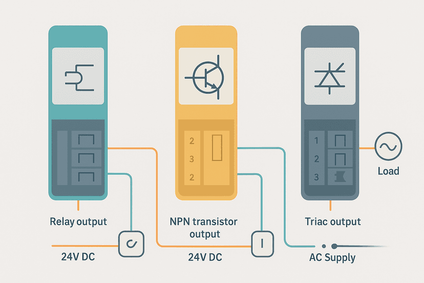
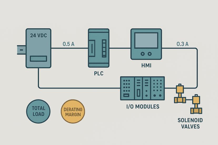
Terminal blocks are just one part of a well-built control panel. Once your terminations are solid, the next step is making sure the wiring between them is correctly routed and segregated. The control panel wire routing and segregation guide covers duct sizing, segregation rules, and bend radius. If you are also wiring PLC outputs and choosing between relay, transistor and triac modules, PLC output wiring explains how each output type affects your terminal block and fusing choices. And if you are sizing the panel power supply to feed everything, start with the 24 VDC power supply sizing guide.
Frequently asked questions
What are DIN rail terminal blocks used for?
What is the difference between screw and spring-clamp terminal blocks?
What size wire can a 4 mm² terminal block accept?
What torque should I use on DIN rail terminal block screws?
How do jumper bars work on terminal blocks?
What is a 35 mm DIN rail?
Can I mix Phoenix Contact and Wago terminal blocks on the same rail?
What is a fused terminal block and when do I need one?
How do I remove a wire from a spring-clamp terminal block?
How many terminal blocks fit on a 35 mm DIN rail?
Learn this by building it
There is a PLC in this site. It runs a real scan engine, checks your logic against the same tests a working machine would fail, and needs no download and no account.
Open the exercisesFree, no signup, runs in your browser. See all 16 exercises.
Was this helpful?