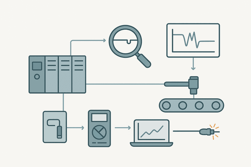
NPN vs PNP Sensors: Wiring and PLC Connection
You order a proximity sensor, wire it up, and the PLC input sits dead. Or worse, it stays on permanently regardless of what the sensor detects. Nine times out of ten the culprit is a mismatch between NPN and PNP. It is one of the most common commissioning mistakes in the industry, and it costs real time. This guide explains the electrical reason behind it, shows you how to match sensor type to input module type, and walks through the wiring for both.
What Is the Difference Between NPN and PNP Sensors?
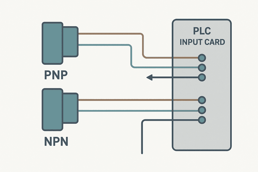
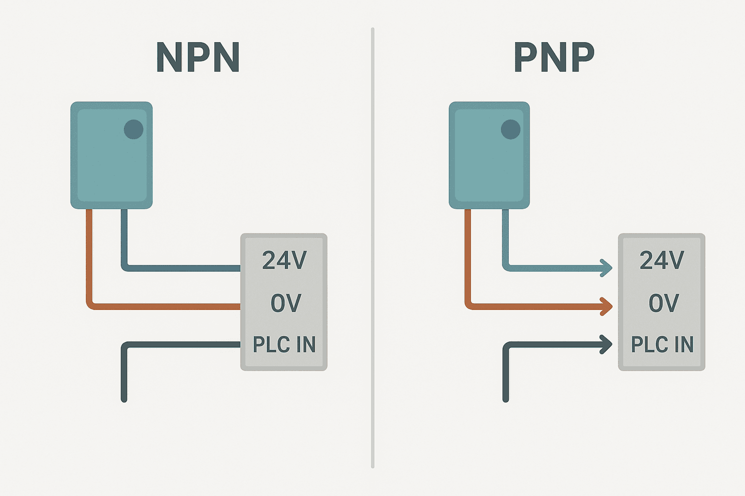
An NPN sensor and a PNP sensor both detect a target and switch an output, but they switch in opposite electrical directions. An NPN sensor switches its output wire to 0V when active. A PNP sensor switches its output wire to the positive supply (typically 24 VDC) when active. The names come from the transistor type used internally to do the switching: an NPN transistor pulls current down toward the negative rail, a PNP transistor pushes current out from the positive rail. In field terms, NPN is called current-sinking and PNP is called current-sourcing.
Why the Direction of Switching Matters to Your PLC Input
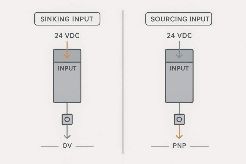
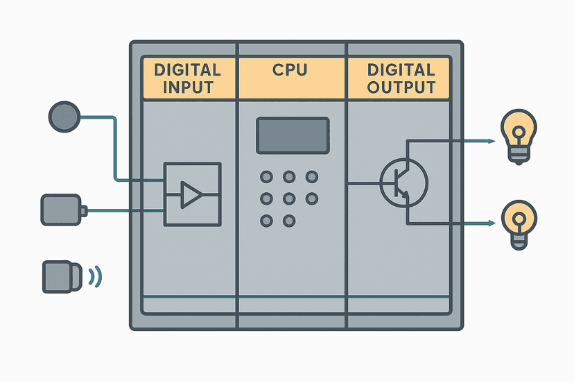
A PLC digital input module does not just look for voltage. It looks for current flowing through its input circuit in a specific direction. That is why the terms sinking and sourcing also apply to input modules, and it is where the confusion starts. If you want a deeper look at how this plays out on the module side, the post on sinking vs sourcing PLC I/O covers the input module perspective in detail.
The rule to memorize is simple: opposites attract. A sinking input module (common wired to 24V) needs a current path from 24V through its input terminal to 0V. Only an NPN sensor can complete that path, because its active state pulls the signal line to 0V. A sourcing input module (common wired to 0V) needs current to flow in from 24V. Only a PNP sensor can push that current. Mismatching the two means no current flows, so the input never activates, or worse, it floats to an unpredictable state.
| Sensor output type | Also called | Output switches to | Matches this input module |
|---|---|---|---|
| NPN | Current-sinking | 0V (signal pulled low) | Sinking input (common at 24V) |
| PNP | Current-sourcing | 24V (signal pushed high) | Sourcing input (common at 0V) |
How to Identify Your PLC Input Module Type
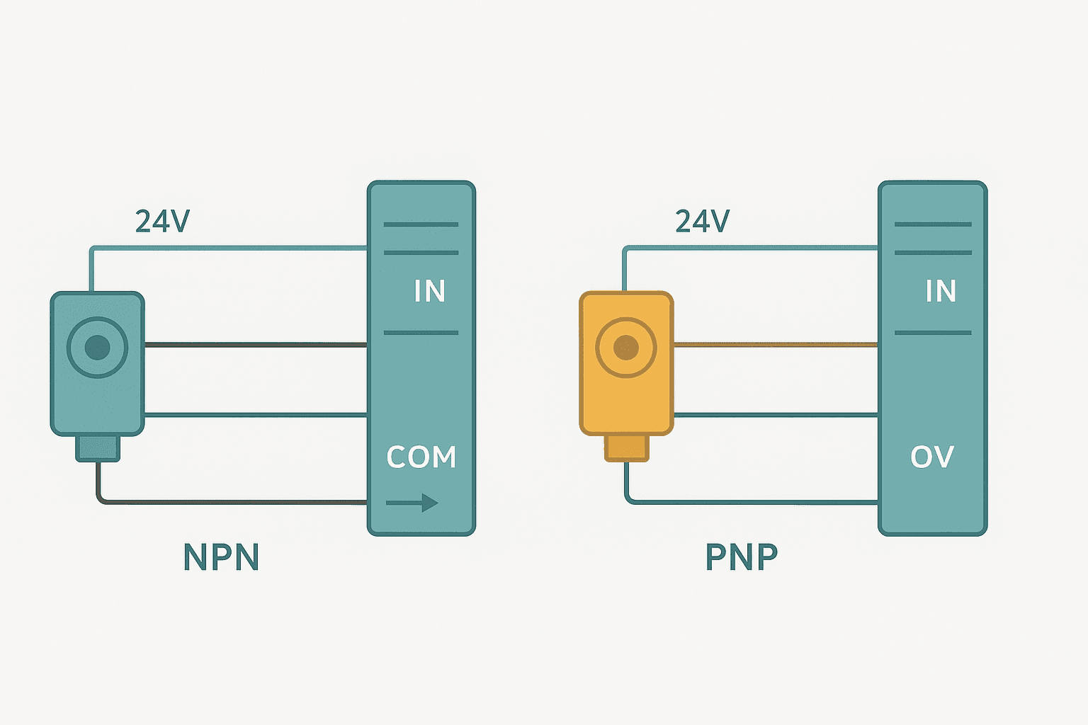
Pull the module datasheet or look at the terminal block label. You are looking for the common terminal, often labelled COM, 1M, 2M or S/S depending on the brand. If COM is connected to the 24V positive supply, the module is a sinking type and you need NPN sensors. If COM is connected to 0V, it is a sourcing type and you need PNP sensors. Some modules like Siemens S7-1200 digital input cards can be configured either way by moving a single jumper or changing a terminal wire, which makes them configurable for either sensor type. For more on how the module circuitry works underneath, see how PLC input and output modules work.
NPN Sensor Wiring Step by Step
Standard 3-wire sensors follow IEC 60947-5-2 colour coding: brown is positive supply, blue is negative supply, black is the switching output. For a full treatment of the 3-wire connection, the post on 3-wire sensor wiring: PNP vs NPN to PLC inputs has detailed diagrams.
- Connect the brown wire to 24 VDC.
- Connect the blue wire to 0V (the negative bus).
- Connect the black output wire to the PLC input terminal.
- Wire the module's COM terminal to 24V (making it a sinking input).
- When the sensor detects a target, the black wire is pulled to 0V. Current flows from COM (24V) through the input circuit to the black wire and out to 0V. The input registers ON.
PNP Sensor Wiring Step by Step
- Connect the brown wire to 24 VDC.
- Connect the blue wire to 0V.
- Connect the black output wire to the PLC input terminal.
- Wire the module's COM terminal to 0V (making it a sourcing input).
- When the sensor detects a target, the black wire is pushed to 24V. Current flows from the black wire through the input circuit to COM (0V). The input registers ON.
The Leakage Current Problem
Solid-state sensors use transistor outputs rather than mechanical contacts, so they always allow a tiny leakage current to flow even when off. Typical values range from 0.1 mA to 1 mA. Most PLC input modules have an OFF-state threshold around 1 to 5V. If the leakage current is large enough to develop a voltage across the input impedance that exceeds this threshold, the input reads as permanently ON even with no target present. You will see this most often with high-impedance input cards.
The fix is a bleed resistor. Place a 10 kohm resistor between the input terminal and the module's COM terminal. This gives the leakage current somewhere to go, dragging the voltage back below the OFF threshold. On 24V systems with a 10 kohm bleed, the leakage voltage stays below 1V even with a 100 microamp leaking sensor. If you are chasing a phantom ON that only clears when you disconnect the sensor, this is almost certainly the cause. The post on PLC digital input faults covers this and other input-side failure modes in full.
When the Sensor Type Does Not Match: What Actually Happens
Connecting a PNP sensor to a sinking input (COM at 24V): both the COM and the black output wire are at 24V when the sensor is active. No voltage difference, no current, the input stays OFF. Connecting an NPN sensor to a sourcing input (COM at 0V): both COM and the black output wire are at 0V when the sensor is active. Same result, no current, input stays OFF. But here is the gotcha that catches people out: the input might actually read ON intermittently due to capacitive coupling on a long cable run, or it might float to an undefined state. That makes the fault look like an intermittent sensor problem rather than a wiring type mismatch. If you are chasing ghosts like that, the article on intermittent sensor faults has a diagnostic process that will help.
Selectable NPN/PNP Sensors: A Practical Option
Many Keyence, Sick and Balluff sensors now ship with a user-selectable output. A small recessed switch or a dedicated teach wire lets you choose NPN or PNP on site. These cost a little more but are worth it on machines that ship to customers with different PLC standards, or when you are managing a spare parts stock and want one part number to cover both cases. On a recent automotive line retrofit I was involved in, we standardised on selectable-output sensors across the whole machine. It cut the spares SKU count by half and removed the type mismatch risk entirely.
Quick Decision Guide: NPN or PNP?
- European machine with Siemens or Pilz I/O: almost certainly PNP sensors on sourcing inputs.
- Japanese machine with Omron or Mitsubishi I/O: check the module, but NPN is common on legacy hardware.
- North American machine with Allen-Bradley or similar: sourcing inputs and PNP sensors are the most common default, but always verify the module wiring diagram.
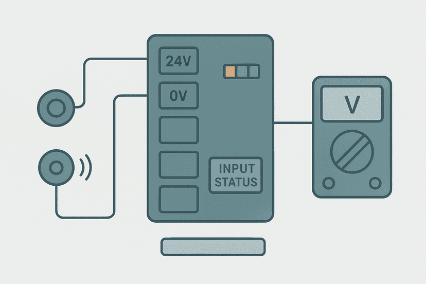
- Unknown module: measure the COM terminal voltage. 24V means sinking, use NPN. 0V means sourcing, use PNP.
- Mixed environment or spare parts simplification: use selectable NPN/PNP sensors.
For diagnosing whether a sensor or the input module is actually at fault once you have the wiring correct, the PLC I/O fault diagnosis with a multimeter guide walks through the voltage measurements step by step. And if you are setting up a fresh input module in TIA Portal, S7-1200 analog inputs: wiring and TIA Portal setup shows how the configuration software side works alongside the physical wiring.
Sensor Output in the PLC Program
Once the sensor is correctly wired and the input registers ON when the target is present, the PLC sees a simple digital bit. Whether you used NPN or PNP is invisible to the ladder logic: the input tag is TRUE when detected and FALSE when not. A normally-open sensor wired correctly appears in ladder as an XIC (Examine If Closed) contact. If you need the logic to respond to the absence of a target, you would use an XIO contact, which is the ladder equivalent of a normally-closed condition. The distinction between those two contact types is explained in XIC vs XIO: ladder logic contacts explained. You can also read about NO vs NC contacts in PLC ladder logic to understand how the physical sensor output state maps to your program logic.
Common Mistakes Summarised
| Mistake | Symptom | Fix |
|---|---|---|
| NPN sensor on sourcing input (COM at 0V) | Input never turns ON | Replace with PNP sensor or rewire COM to 24V |
| PNP sensor on sinking input (COM at 24V) | Input never turns ON | Replace with NPN sensor or rewire COM to 0V |
| Solid-state sensor leakage causing false ON | Input stuck ON with no target present | Add 10 kohm bleed resistor from input terminal to COM |
| Brown and blue wires swapped | Sensor does not power up or is damaged | Correct supply polarity: brown to 24V, blue to 0V |
| Ignoring sensor wire colour and guessing | Random faults, possible sensor damage | Always verify against sensor datasheet, not just colour |
Keep Learning
Now that the NPN vs PNP distinction is clear, the logical next step is understanding how the PLC input module itself processes that signal and what can go wrong inside the module. Start with how PLC input and output modules work for the full picture, then read PLC digital input faults: how to diagnose them to build a solid troubleshooting method. If you want to go deeper on the sinking and sourcing terminology from the module side, sinking vs sourcing PLC I/O: wiring it right ties everything together.
Frequently asked questions
What is the difference between NPN and PNP sensors?
How do I know if my PLC input module needs NPN or PNP sensors?
Can I use an NPN sensor on a sourcing PLC input?
What do the wire colors mean on a 3-wire sensor?
Can a sensor be both NPN and PNP?
Why does my PLC input stay ON even when the sensor is not detecting anything?
Do NPN sensors work better over long cable runs?
Is NPN or PNP more common in Europe versus Asia?
Can I wire a 4-wire sensor to a PLC input?
What is sensor leakage current and why does it matter for PLCs?
Now build it
You have just read about XIC and XIO. Reading a rung and making one behave are different skills, and the second one is the job.
Start / Stop Circuit
Beginnerabout 10 minThe first circuit every controls engineer learns: a motor that starts on a button press, keeps running when the button is released, and stops on a stop button, with stop always winning.
Build this rungFree, no signup, runs in your browser. See all 16 exercises.
Was this helpful?