Inductive vs Capacitive Proximity Sensors: Full Guide
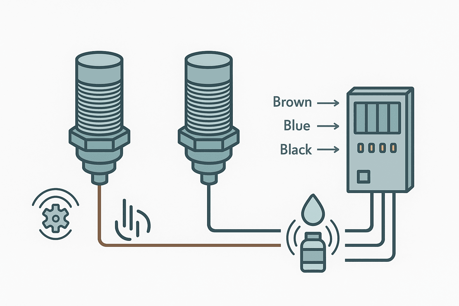
Pick up an inductive and a capacitive proximity sensor from the same manufacturer and they will likely share the same M18 barrel, the same three-wire cable, the same connector, and almost the same datasheet layout. Wire them up and they both give you a clean 24 V DC signal that drives a PLC digital input. So why does choosing the wrong one cause so much grief on the plant floor? Because the physics underneath are completely different, and that physics dictates which materials the sensor will reliably detect, how far away it will see them, and what environmental factors will make it lie to you.
What Is the Difference Between Inductive and Capacitive Proximity Sensors?
An inductive proximity sensor detects electrically conductive targets, almost always metals, by generating a high-frequency electromagnetic field at its face. When a metal object enters that field, eddy currents form in the target and absorb energy from the oscillator. The sensor's internal circuit detects that energy drop and switches its output. A capacitive proximity sensor instead creates an electrostatic field. Any material with a dielectric constant higher than air, including plastics, liquids, wood, grain and yes, metals too, disturbs that field and triggers the output. This 40-to-55-word distinction is the root of every selection decision you will make.
How Each Sensor Type Works: The Physics in Plain Language
Inductive Sensors: Eddy Currents Do the Work
Inside the sensor head is an LC oscillator, a coil wound on a ferrite core, running at somewhere between 100 kHz and 1 MHz depending on the design. The coil projects a field forward from the sensing face. When a conductive target enters, Lenz's law kicks in and eddy currents circulate through the target, opposing the inducing field. This damps the oscillation. A threshold detector monitors oscillation amplitude and switches the output transistor when the amplitude drops below a set level. Pull the metal target away and the oscillation recovers, the transistor switches back. The whole process is fast, typically 1 to 5 ms response time, repeatable to fractions of a millimetre, and completely unaffected by non-conductive materials like dust, oil mist or plastic packaging.
One thing that catches engineers out is the reduction factor. Inductive sensors are rated for mild steel (Fe360). If your target is aluminum, stainless steel, or copper, the sensing range shrinks, sometimes dramatically. See the table below for typical multipliers. I have had a commissioning job where an M18 sensor rated 8 mm on steel was placed 7 mm from an aluminum cam lobe. It never triggered. Datasheet in hand, the reduction factor for aluminum on that model was 0.35, giving a real range of 2.8 mm. Moving the bracket 4 mm fixed it.
| Target Material | Typical Reduction Factor | Effective Range (8 mm rated sensor) |
|---|---|---|
| Mild steel (Fe360) | 1.0 | 8 mm |
| Stainless steel 304 | 0.70 to 0.85 | 5.6 to 6.8 mm |
| Aluminum | 0.35 to 0.40 | 2.8 to 3.2 mm |
| Brass / copper | 0.35 to 0.50 | 2.8 to 4.0 mm |
| Cast iron | 0.90 to 1.0 | 7.2 to 8.0 mm |
Capacitive Sensors: Dielectric Constant Is Everything
A capacitive sensor has two electrodes built into the face that form a small capacitor with the air in front of them. The sensor's oscillator frequency or amplitude changes when a material with a dielectric constant (Er) greater than air (Er = 1) enters the field. Water has an Er around 80, most plastics sit between 2 and 5, and dry grains like wheat are around 3 to 5. The higher the Er, the easier and farther the sensor detects the material. This is why capacitive sensors are ideal for level detection of liquids through a plastic tank wall, and why they are the go-to for detecting non-metallic parts on a conveyor.
Most capacitive sensors have a small potentiometer on the body for sensitivity adjustment. This is not a gimmick; it is essential. You use it to set the detection threshold so the sensor triggers on the target material but not on the container wall, mounting bracket, or ambient humidity. Get it wrong and you end up with continuous false triggers or a sensor that never fires. When commissioning a level sensor through a plastic pipe, always set sensitivity with the pipe empty first, then introduce the liquid and confirm the output switches cleanly.
Sensing Range: Real Numbers and What Affects Them
Both sensor types quote a nominal sensing distance (Sn) at rated voltage, 23 degrees C, against a standard target. For inductive sensors that standard target is a square of mild steel with sides equal to three times the sensor diameter, or 1 mm thick, whichever is larger. For capacitive sensors it is a square grounded metal plate. Practical operating range is usually 0 to 81% of Sn to stay within hysteresis and temperature variation. A sensor marked 8 mm Sn is safe to use up to about 6.5 mm in production.
Temperature matters more than most people expect. Inductive sensors can drift 10 to 15% across a 0 to 70 degrees C range. In a furnace area or a cold store, that drift can push a borderline installation into intermittent operation. If you are chasing intermittent sensor faults, temperature-induced range variation is one of the first suspects. Capacitive sensors drift more because the dielectric constant of most materials is also temperature dependent, which is why food and beverage applications often need sensors with active temperature compensation.
Shielded vs Unshielded: Mounting Matters
Both inductive and capacitive sensors come in shielded (flush-mount) and unshielded variants. A shielded sensor wraps the coil or electrodes in a metal sleeve that concentrates the sensing field forward and prevents the bracket from entering the field. You can install a shielded sensor flush with the face of a steel mounting plate and it will not false-trigger on the plate. An unshielded sensor projects a wider, longer-range field but requires free space around the barrel, typically equal to the sensor diameter on all sides, to avoid bracket interference.
Wiring to a PLC Input: Both Types Work the Same Way
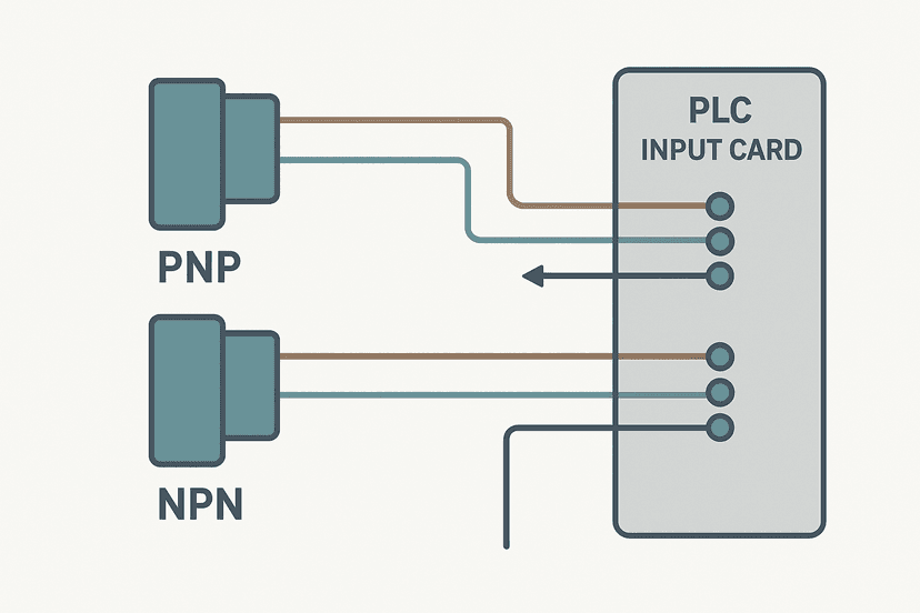
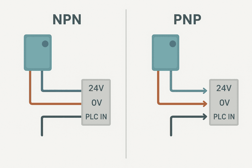
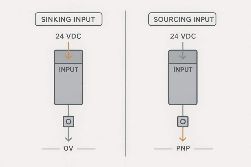
Here is the good news: from a wiring standpoint, inductive and capacitive proximity sensors are interchangeable. Both come in PNP (sourcing) and NPN (sinking) output versions. The standard three-wire color code is brown for positive supply (typically 10 to 30 V DC), blue for negative or common, and black for the switching output. The output wire connects to the PLC digital input terminal. For a thorough walkthrough of the PNP and NPN output differences and which input module topology each suits, see 3-Wire Sensor Wiring: PNP vs NPN to PLC Inputs and NPN vs PNP Sensors: Wiring and PLC Connection. The sinking vs sourcing PLC I/O post explains which input card type to pair with each.
If you are working with a Siemens S7-1200 and need to configure the input channel after wiring, the S7-1200 Analog Inputs guide covers the TIA Portal side of I/O setup in detail. For diagnosing problems after wiring, PLC Digital Input Faults: How to Diagnose Them and PLC I/O Fault Diagnosis with a Multimeter are the practical next steps.
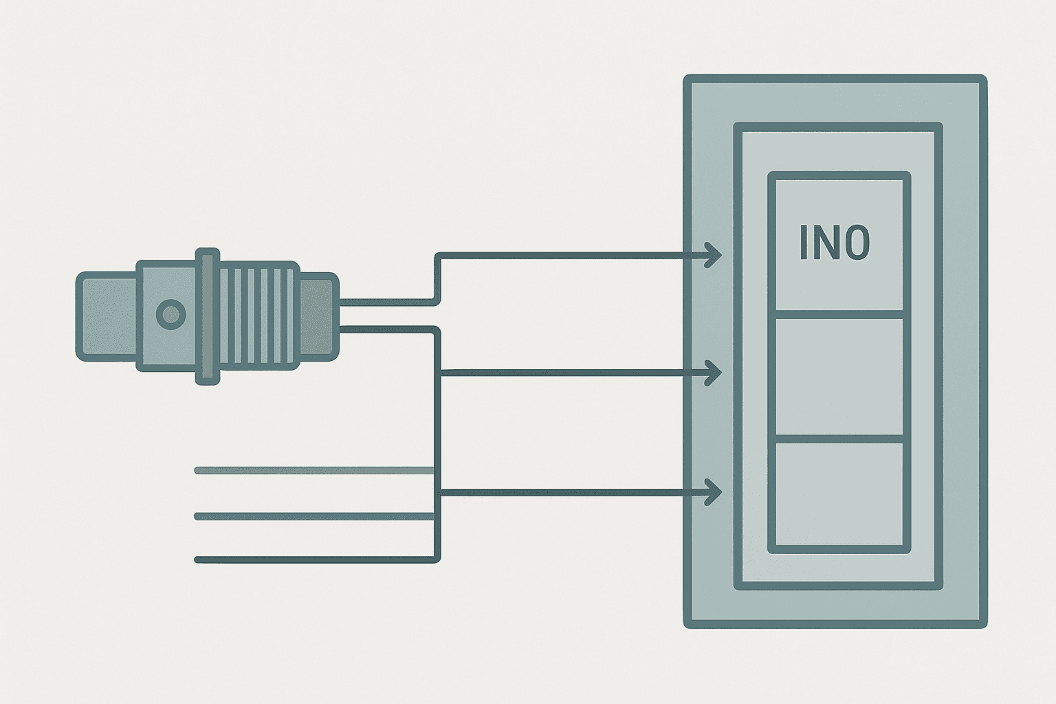
One wiring gotcha specific to capacitive sensors: the sensitivity pot is adjusted with the sensor live and installed in its final position. That means you are working near the machine. Always follow your site's electrical safety procedures. A lot of engineers adjust the pot, walk away, and discover the sensor is now falsely triggered by a nearby conveyor frame. Adjust it, then cycle the actual target a dozen times to confirm stable switching. If the output chatters at the edge of the sensing range, you have either set sensitivity too high or your target surface is irregular.
Environmental Factors: Where Each Sensor Wins or Loses
Inductive sensors are genuinely tough in dirty environments. Coolant, cutting oil, metal chips, and weld spatter do not affect the electromagnetic field at all. The sensor face can be contaminated with non-conductive material and it will still fire reliably. This is why inductive sensors dominate CNC machine tools, stamping presses, and metal fabrication. Capacitive sensors, on the other hand, are sensitive to anything on their face because surface contamination adds to the dielectric load. A film of water or oil on a capacitive sensor face can cause continuous false triggering. IP69K rated models with a guard ring help, but inductive is almost always the better call in a wet-metal environment.
Conversely, capacitive sensors are the only practical choice for non-metallic detection on a conveyor, for detecting grain level in a silo, or for confirming a plastic cap is seated on a bottle. Inductive sensors simply will not see these targets at all. In packaging and food processing, you will often see both sensor types on the same machine: inductive for detecting the metal indexing cam and capacitive for confirming the plastic container is present.
Quick Selection Guide: Which Sensor for Which Job
| Application | Recommended Type | Key Reason |
|---|---|---|
| Detecting steel or cast-iron parts | Inductive | Maximum range and repeatability on ferrous targets |
| Detecting aluminum or brass parts | Inductive (check reduction factor) | Still detects, but range is reduced; verify clearance |
| Detecting plastic parts on a conveyor | Capacitive | Inductive cannot see non-conductive materials |
| Liquid level through a plastic tank wall | Capacitive | High dielectric constant of water gives reliable through-wall detection |
| Detecting powder or grain fill level | Capacitive | Dielectric contrast between air and material triggers output |
| Metal detection near coolant or chips | Inductive | Immune to non-conductive contamination on sensing face |
IO-Link Variants: More Than Just On and Off
Both inductive and capacitive sensors are now available with IO-Link outputs alongside the traditional PNP/NPN switching output. An IO-Link sensor sends its switching status digitally but also streams additional data: measured distance value, temperature at the sensor head, signal quality, and diagnostic flags. This is useful for predictive maintenance because you can trend the actual measured gap and get an alert when it drifts toward the switching threshold rather than waiting for an intermittent fault to appear. The IO-Link Explained post covers how the protocol integrates with a PLC master port.
A Practical Ladder Logic Example: Sensor Debounce on a Capacitive Input
Capacitive sensors on granular or liquid targets can chatter at the switching point if the material surface is turbulent. The sensor output oscillates rapidly as the surface level hovers around the detection threshold. A simple TON debounce rung in your PLC program filters this out: the output only becomes active if the sensor has been continuously on for a defined period, say 200 ms. This gives the surface time to settle before the PLC acts.
Capacitive Level Sensor Debounce with TON (Studio 5000). Ladder logic (4 rungs): Rung 0: examine if Level_CapSensor is on (XIC), then TON on Level_Debounce. Rung 1: examine if Level_Debounce.DN is on (XIC), then examine if Level_FaultLatch is off (XIO), then energize output Level_Confirmed (OTE). Rung 2: examine if Level_Confirmed is on (XIC), then latch output Fill_Valve_Close (OTL). Rung 3: examine if Level_FaultLatch is on (XIC), then unlatch output Fill_Valve_Close (OTU). The capacitive level sensor input is gated through a 200 ms TON debounce timer. Level_Confirmed only asserts when the sensor has held on continuously for the full dwell period, filtering surface turbulence chatter. A fault latch overrides the valve-close output for safety.
The diagram above evaluates one scan. Run these exact rungs on a real scan cycle to watch the latching and the timers behave.
Run this in the simulatorYou can practice a similar debounce pattern yourself in the browser using the interactive debounce exercise on this site. It lets you toggle a noisy input and watch how the timer filters the transitions in real time.
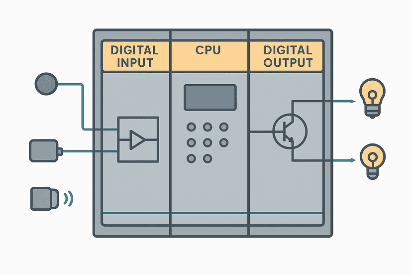
For more on how PLC input modules process these signals, How PLC Input and Output Modules Work is worth reading alongside this post. And if you are building a system where the PLC needs to act on sensor data across a network rather than a direct hardwired input, IO-Link Explained covers the bridge between smart sensors and the controller.
What to Read Next
If this post helped clarify which sensor type to reach for, the next logical step is nailing down the wiring. Start with 3-Wire Sensor Wiring: PNP vs NPN to PLC Inputs for the full color-code and termination walkthrough, then check Sinking vs Sourcing PLC I/O: Wiring It Right to confirm your input card polarity matches the sensor output type. Once everything is wired, use the How to Test a PLC Input guide to verify the signal end to end before you go live.
Frequently asked questions
What is the main difference between inductive and capacitive proximity sensors?
Can a capacitive proximity sensor detect metal?
What sensing range can I expect from each sensor type?
Do inductive and capacitive sensors wire to the PLC the same way?
Why does my capacitive sensor trigger on the pipe wall instead of the liquid inside?
What is a reduction factor and why does it matter for inductive sensors?
Can I use a capacitive sensor to detect product inside a closed metal enclosure?
How do I stop a capacitive sensor from false-triggering due to humidity or condensation?
Is a 2-wire or 3-wire proximity sensor better for a PLC input?
What is the difference between shielded and unshielded proximity sensors?
Now build it
You have just read about TON. Reading a rung and making one behave are different skills, and the second one is the job.
Flasher
Intermediateabout 15 minTwo timers chained in a loop make a lamp blink: the classic two-TON flasher used for warning beacons everywhere. Your first taste of timers driving each other.
Build this rungFree, no signup, runs in your browser. See all 16 exercises.
Was this helpful?