Proximity Sensor Wiring to a PLC: Full Guide
Proximity sensor wiring to a PLC trips up more people than almost any other commissioning task. The sensor lights up, the input stays dark, and you spend an hour chasing a wiring mistake that should have taken five minutes to avoid. This guide covers every wire count and output type you will encounter in the field: 2-wire, 3-wire PNP, 3-wire NPN, and 4-wire sensors, with the color codes, the input module rules, and the specific gotchas that actually bite people.
What Is Proximity Sensor Wiring to a PLC?
Proximity sensor wiring to a PLC means connecting the sensor's power supply and signal output wires to the correct PLC input module terminals so the controller sees a reliable digital on/off signal when an object enters the detection range. The sensor needs a DC supply (almost always 10 to 30 V DC, typically 24 V DC), and its switching output connects to the PLC input terminal. Getting the polarity and the NPN/PNP type matched to the input module type is the entire job.
Wire Color Codes: What Each Wire Does
The IEC 60947-5-2 standard defines the color code used by virtually every mainstream proximity sensor brand including Balluff, IFM, Turck, Sick, Omron and Pepperl+Fuchs. Stick this table on the panel door during commissioning.
| Wire Color | Function | Connect To |
|---|---|---|
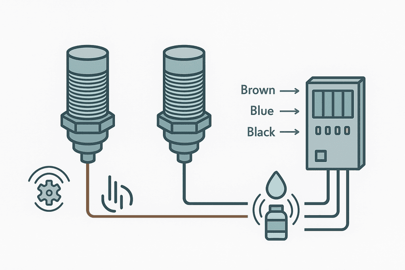
| Brown | Plus supply (+V) | Positive 24 V DC rail |
| Blue | Negative supply (0 V) | 0 V / DC common rail |
| Black | Switching output (NO) | PLC input terminal |
| White | Second output (NC, 4-wire only) | Second PLC input terminal or spare |
PNP vs NPN: Matching the Sensor Output to the Input Module
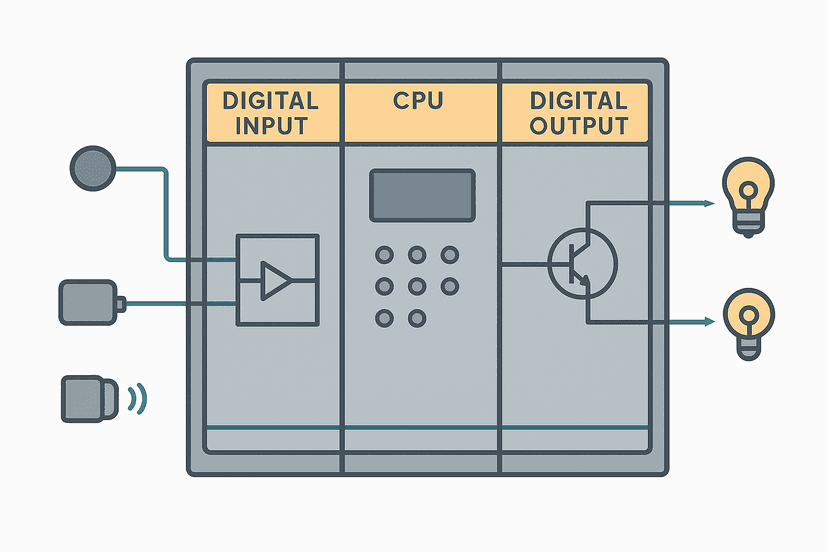
This is the single most common wiring error. The NPN vs PNP sensor type determines which direction current flows through the signal wire, and the PLC input module must be configured to match. You can find a deeper treatment of the input module side in the sinking vs sourcing PLC I/O guide.
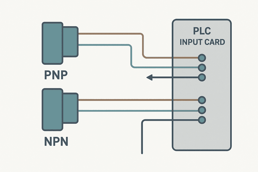
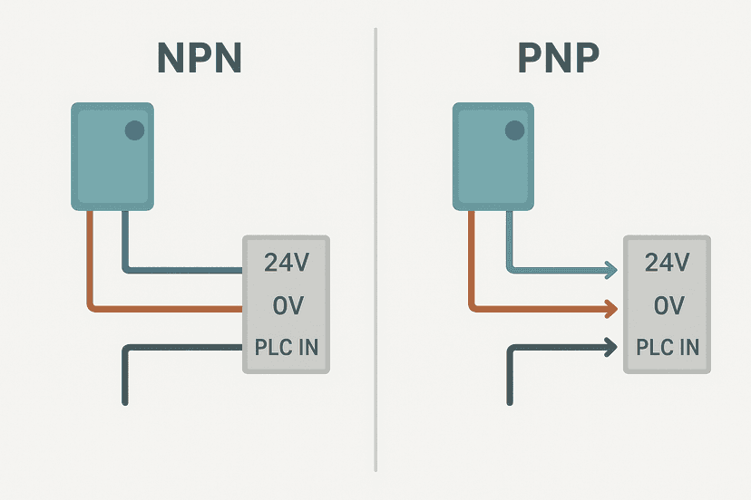
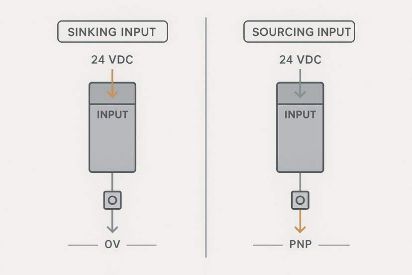
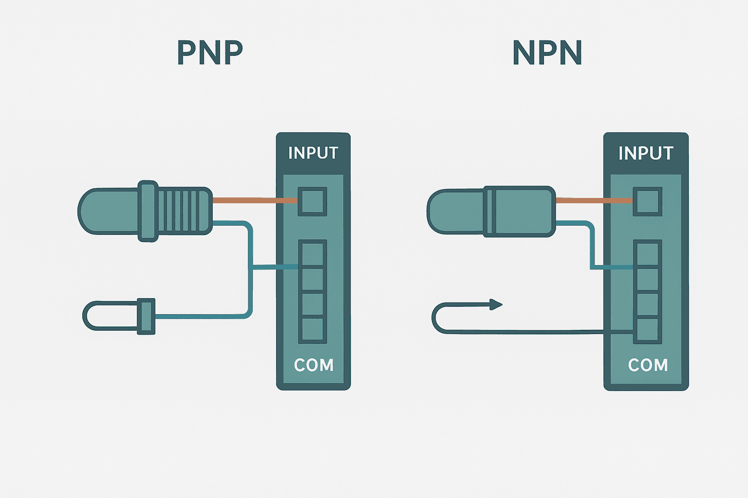
- PNP sensor (sources current): When the target is detected, the internal transistor switches the black signal wire to the positive supply voltage. Current flows out of the sensor into the PLC input terminal. This needs a sourcing input module (also called a PNP input or Type 1 input in IEC terminology). It is the standard choice in European panels and most modern North American designs.
- NPN sensor (sinks current): When the target is detected, the transistor switches the black wire to 0 V. Current flows out of the PLC input terminal into the sensor. This needs a sinking input module (also called an NPN input). Common in older North American panels and some Asian equipment.
- Rule of thumb: PNP sensor goes to sourcing input. NPN sensor goes to sinking input. Mixing these will give you a constant-on or constant-off input, never a reliable signal.
Many modern PLC input modules are bipolar or auto-sensing and accept both PNP and NPN. Check the module datasheet before assuming. The how PLC input and output modules work article goes into the internal circuitry if you want to understand why the polarity matters.
How to Wire a 2-Wire Proximity Sensor
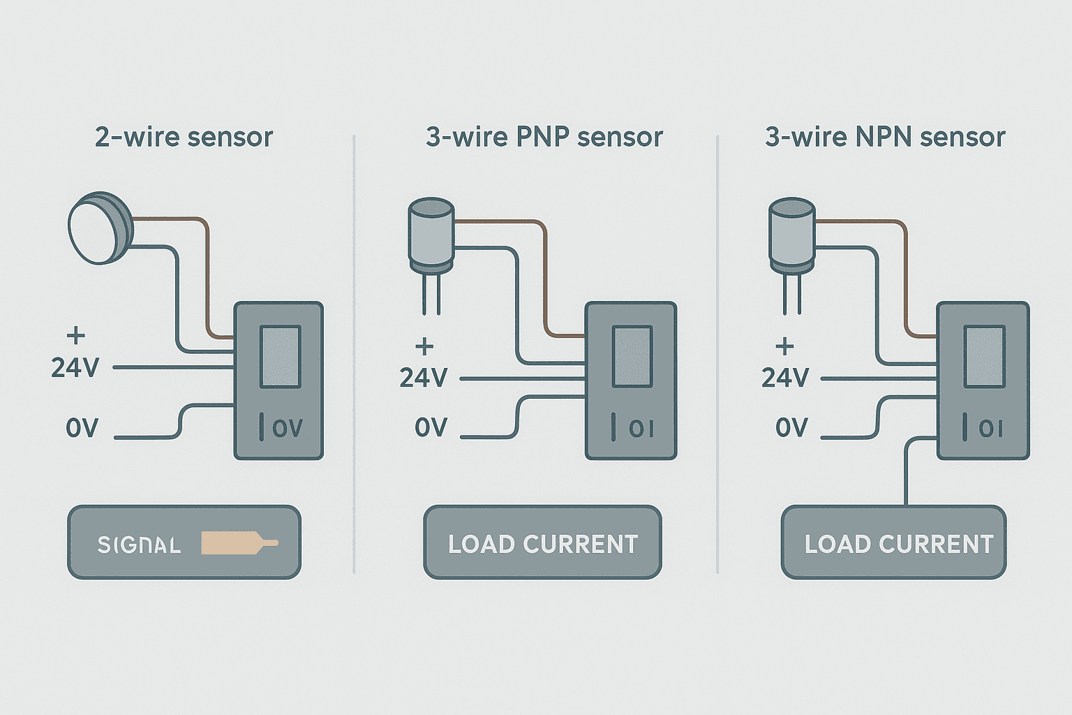
A 2-wire sensor has only a brown and a blue wire. It sits in series with the PLC input circuit the same way a mechanical switch does. The sensor draws a small leakage current (typically 0.8 to 1.7 mA) even when no target is present, to power its internal electronics. Brown goes to the positive supply, blue goes to the PLC input terminal, and the module's input common connects to 0 V.
The gotcha: that off-state leakage can be high enough to turn on a sensitive PLC input. Some Siemens SM 1221 and Rockwell 1734-IB8 inputs have a minimum OFF-state voltage threshold around 5 V. If the leakage current times the input impedance exceeds that threshold, the input reads ON permanently. The fix is a parallel bleed resistor across the input terminal and common, typically 6.8 kOhm to 10 kOhm at 24 V DC. Check the sensor's leakage current spec and the module's off-state current threshold before installing any 2-wire device.
How to Wire a 3-Wire Proximity Sensor
Three-wire sensors are the most common type you will encounter. They have a dedicated power supply circuit and a separate transistor output, so leakage current is not a problem. Wiring is straightforward:
- Brown wire to the positive 24 V DC supply terminal.
- Blue wire to the 0 V DC common rail.
- Black wire (signal output) to the PLC input terminal.
- Confirm the input module common is connected to 0 V (for sourcing input with PNP sensor) or to 24 V (for sinking input with NPN sensor).
Step 4 is where people get confused. For a PNP sensor on a sourcing input module, the module's COM terminal connects to 0 V. When the sensor fires, it drives the input pin to 24 V, current flows through the input circuit to COM at 0 V, and the module registers an ON. For an NPN sensor on a sinking input module, the COM terminal connects to 24 V, and the sensor pulls the input pin down to 0 V to register an ON. The 3-wire sensor wiring guide has wiring diagrams for both cases if you want a visual reference.
How to Wire a 4-Wire Proximity Sensor
A 4-wire sensor adds a white wire as a second complementary output. The black wire is normally open (output OFF when no target, ON when target detected). The white wire is normally closed (output ON when no target, OFF when target detected). You can use both outputs independently on two separate PLC input channels if your application needs it, which saves buying a second sensor.
If you only need one output, connect the unused wire with a piece of tape over the end. Never let a floating transistor output touch anything conductive. And do not tie the two outputs together: they are complementary, not parallel, so shorting them together inside the sensor will damage the output stage.
Supply Voltage, Cable Length and Filtering
Most inductive and capacitive proximity sensors run on 10 to 30 V DC. The 24 V DC standard used in most panels sits comfortably in the middle of that range, which gives you margin for voltage drop over long cable runs. On a 0.34 mm2 cable at 100 m, you lose roughly 1.5 V at 100 mA supply current. That is fine. At 200 m you should check your 24 VDC power supply sizing and the voltage at the sensor terminals with a meter.
Cable capacitance matters too. Long runs create a capacitive load that slows the sensor's switching edges and reduces its maximum switching frequency. A 100 m run of standard sensor cable adds roughly 20 to 25 nF of capacitance. For a position sensor on a slow conveyor this is irrelevant, but for a high-speed part counter running at 5 kHz, it is not. Check the sensor's rated switching frequency against the cable length in the datasheet.
Electrical noise from VFDs and contactors is a real problem. Route sensor cables away from power cables, use shielded cable on runs longer than a few metres, and ground the shield at the panel end only. The cable shield grounding guide explains why single-end grounding is usually the right call. If you still get noise-induced false triggers, a small input filter in the PLC software (typically 1 to 8 ms debounce) will clean it up. On intermittent sensor faults, noise is usually the first suspect.
A Proximity Sensor Debounce Rung in Ladder Logic
If a proximity sensor chatters on a vibrating machine, a short software debounce timer is the cleanest fix. The rung below (Rockwell Studio 5000 style) only confirms the input after it has been stable for 8 ms, which eliminates mechanical vibration bounce without adding meaningful delay to a normal detect cycle.
Inductive Proximity Sensor Debounce with TON (Studio 5000). Ladder logic (4 rungs): Rung 0: examine if Prox_Part_Raw is on (XIC), then TON on Prox_Debounce. Rung 1: examine if Prox_Debounce.DN is on (XIC), then examine if Input_FaultLatch is off (XIO), then energize output Prox_Part_Confirmed (OTE). Rung 2: examine if Prox_Part_Confirmed is on (XIC), then latch output Part_Present_Latch (OTL). Rung 3: examine if Prox_Part_Raw is off (XIO), then RES on Prox_Debounce, then either unlatch output Part_Present_Latch (OTU). Rung 1 starts a TON only while the raw sensor input is ON. Rung 2 sets the confirmed bit only after 8 ms of continuous ON, and gates out any active fault. Rung 3 latches the part-present state. Rung 4 resets the timer and unlatches part-present as soon as the raw sensor drops, keeping the confirmed bit tight to the actual detection window.
The diagram above evaluates one scan. Run these exact rungs on a real scan cycle to watch the latching and the timers behave.
Run this in the simulatorYou can try this exact debounce pattern yourself in the interactive debounce exercise on this site. Toggle the raw input and watch how the confirmed output only follows after the timer completes.
Common Proximity Sensor Wiring Mistakes
- PNP sensor on a sinking input (or vice versa). The most common mistake. The input stays permanently ON or permanently OFF. Fix: verify sensor type from the datasheet and match the input module type.
- Brown and black wires swapped. The sensor will not power up or will immediately fail. Always confirm with a meter before energising.
- Leakage current from a 2-wire sensor turning on the input. Add a bleed resistor (6.8 kOhm to 10 kOhm) across the input terminal and common.
- No 0 V reference at the input module COM terminal. The input circuit has no return path and will float. COM must be tied to 0 V for PNP sensors on sourcing inputs.
- Running sensor cable in the same conduit as motor power cables. Induced noise will cause intermittent false triggers. Separate by at least 150 mm or use shielded cable.
- Ignoring the sensor's sensing distance reduction factor on non-ferrous metals. A sensor rated 8 mm on mild steel may only sense 4 mm on aluminium. Check the reduction factor in the datasheet.
If you are chasing a wiring fault systematically, the PLC digital input fault diagnosis guide and the PLC I/O fault diagnosis with a multimeter article both give a structured approach. For the sensor technology differences between inductive and capacitive types, see inductive vs capacitive proximity sensors.
From the Field: The Phantom Part Problem
On a packaging line commissioning a few years back, a Balluff BES M08 inductive sensor was counting phantom parts at roughly one false count every 40 seconds. The sensor was correctly wired PNP to a sourcing input, the indicator LED was solid, and swapping the sensor made no difference. Turned out the sensor cable was running parallel to the 3-phase feed for a 7.5 kW conveyor drive for about 3 metres inside a shared cable tray. The VFD switching frequency was inducing just enough voltage into the sensor cable to briefly cross the input threshold. Rerouting the cable away from the power cable and adding shielded cable on that segment fixed it completely. The PLC panel electrical noise guide covers exactly this kind of problem.
Quick Reference: Sensor Type to Input Module Wiring
| Sensor Type | Signal Wire Behavior | Required Input Module | COM Terminal |
|---|---|---|---|
| 2-wire (AC/DC) | Series switch, leakage in OFF state | Sourcing or sinking (check leakage spec) | 0 V (DC) or Neutral (AC) |
| 3-wire PNP | Signal switches to +V on detect | Sourcing input | 0 V DC |
| 3-wire NPN | Signal switches to 0 V on detect | Sinking input | +24 V DC |
| 4-wire PNP | Black: NO output, White: NC output | Sourcing input (two channels) | 0 V DC |
If you need to verify your wiring is correct before connecting to the PLC, the how to test a PLC input guide shows the multimeter steps that confirm a sensor output is switching correctly at the terminal before you rely on the PLC status LED.
Keep Learning
Now that the wiring is correct, the next step is making sure your ladder logic handles the sensor signal cleanly. Try the interactive debounce exercise to see the TON debounce pattern in action, or work through the parts counter exercise to see how a confirmed proximity sensor input drives a CTU batch count. For a deeper look at how the PLC input module processes the signal once it arrives, the how PLC input and output modules work article is the logical next read.
Frequently asked questions
What do the wire colors mean on a proximity sensor?
What is the difference between a PNP and NPN proximity sensor?
Can I connect a PNP sensor to a sinking PLC input?
How does a 2-wire proximity sensor work?
What is the fourth wire on a 4-wire proximity sensor?
Why does my proximity sensor light up but the PLC input stays off?
Do I need an external load resistor with a 3-wire proximity sensor?
What cable length is safe for proximity sensor wiring?
Can I use a proximity sensor on an AC PLC input?
Now build it
You have just read about TON. Reading a rung and making one behave are different skills, and the second one is the job.
Flasher
Intermediateabout 15 minTwo timers chained in a loop make a lamp blink: the classic two-TON flasher used for warning beacons everywhere. Your first taste of timers driving each other.
Build this rungFree, no signup, runs in your browser. See all 16 exercises.
Was this helpful?