Photoelectric Sensors: Types, Wiring and PLC Use
Photoelectric sensors are probably the most versatile discrete sensor you will wire to a PLC input. They detect objects without touching them, work across large distances, and come in configurations that handle everything from shiny metal cans to translucent packaging film. But pick the wrong mode, wire it to the wrong input type, or mount it an inch too far, and you will spend a shift chasing ghost faults. This guide covers the three main operating modes, wiring to a PLC, output type selection and the real-world problems that trip people up.
What Is a Photoelectric Sensor in a PLC System?
A photoelectric sensor detects the presence, absence, distance or position of an object by emitting a beam of light (typically infrared or visible red laser) and measuring what returns to a receiver. When the detection condition is met, the sensor switches its output ON or OFF, delivering a discrete 24 VDC signal directly to a PLC digital input module. The PLC reads that signal every scan cycle and acts on it in ladder logic or structured text.
Three Photoelectric Sensor Operating Modes
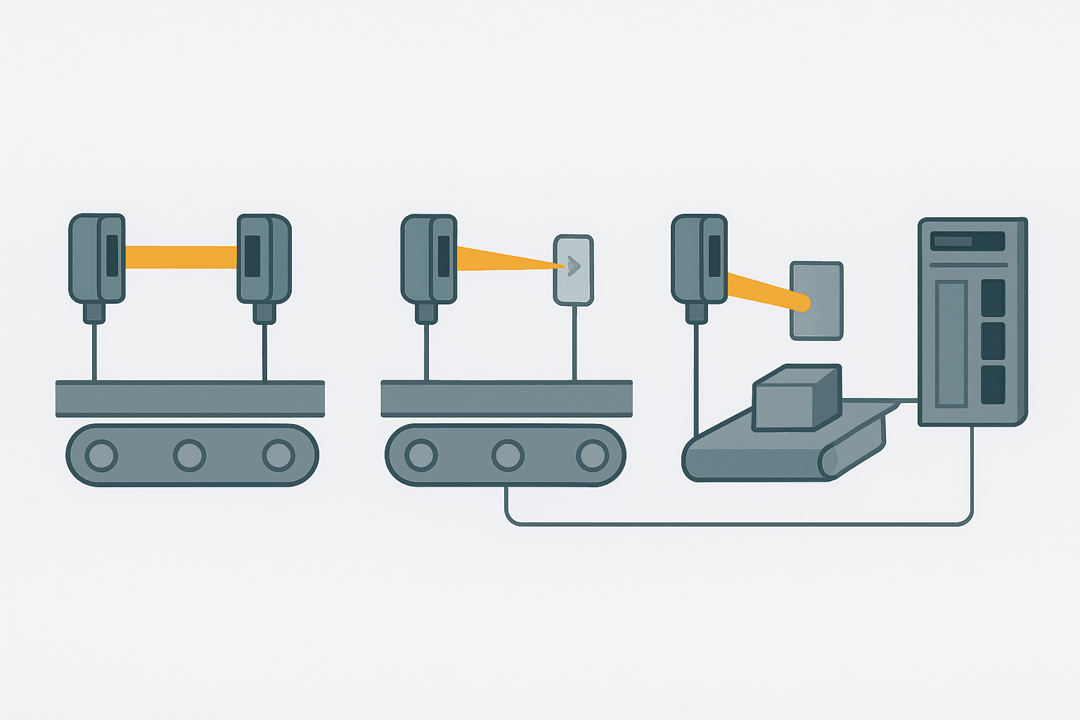
The operating mode determines the physical installation, the achievable range, and what types of targets the sensor handles reliably. Getting this choice right at the design stage saves a lot of pain.
Through-Beam (Opposed Mode)
The emitter and receiver are separate units mounted facing each other across the detection zone. An object triggers the sensor by breaking the beam. This mode offers the longest range (5 to 60 m on most industrial units), the highest immunity to surface colour and reflectivity, and reliable detection of transparent objects like glass bottles or clear film. The downside is that you need conduit runs and wiring to two separate locations, which adds installation cost.
Through-beam is the right choice for wide conveyor gaps, end-of-line gates, or any application where the target is clear or semi-transparent. I have used Keyence's PZ-G series for detecting clear PET bottles on a filling line, and through-beam was the only mode that worked without constant nuisance trips.
Retro-Reflective Mode
Emitter and receiver share a single housing. The sensor fires a beam at a corner-cube reflector mounted on the opposite side, and the receiver looks for that returned beam. An object breaks the path between sensor and reflector, triggering the output. Range is typically 0.1 to 10 m depending on reflector size. You only need to wire one device, but you do need to mount and align the reflector, which is still two mechanical fixings.
One gotcha: shiny objects (polished metal cans, reflective labels) can bounce enough light back to the receiver to fool the sensor into thinking the beam is unbroken even when the target IS in the beam path. Polarised retro-reflective sensors add a polarising filter that only accepts light polarised by the corner-cube reflector, rejecting reflections from shiny targets. If your product is specular, specify the polarised version.
Diffuse (Proximity) Mode
Emitter and receiver are again in one housing, but this time the sensor uses light reflected directly from the target surface. No reflector needed. This is the simplest installation: one device, one mounting bracket, one cable run. Range is limited, typically 20 to 300 mm for standard diffuse sensors, though background-suppression (BGS) variants extend that to 1 to 2 m while ignoring anything beyond the set distance window.
Standard diffuse sensors are sensitive to target colour and surface finish because dark or matte targets absorb more light and return a weaker signal. A BGS sensor using triangulation is far more consistent across mixed-colour products. Use diffuse mode for close-range presence detection where running wiring to a second location or a reflector is impractical.
| Mode | Range | Wiring Points | Best For | Avoid When |
|---|---|---|---|---|
| Through-beam | 5 to 60 m | 2 (emitter + receiver) | Clear objects, wide gaps, high reliability | Wiring to two sides is impractical |
| Retro-reflective | 0.1 to 10 m | 1 + reflector | Medium range, one-side access | Shiny/specular targets (use polarised variant) |
| Diffuse standard | 20 to 300 mm | 1 | Close range, simple install | Mixed colours, dark targets, background clutter |
| Diffuse BGS | 50 mm to 2 m | 1 | Mixed products, background rejection needed | Transparent objects |
Photoelectric Sensor Output Types and PLC Input Matching
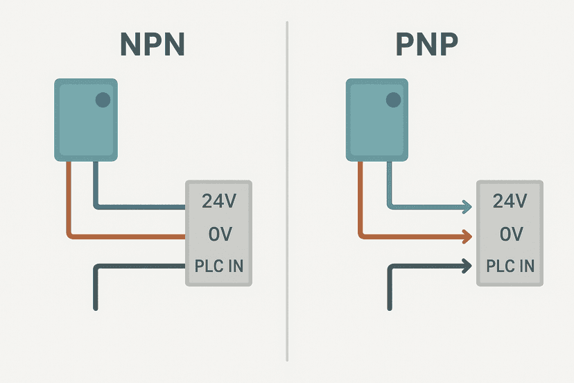
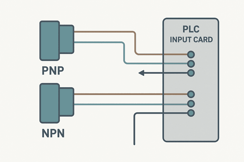
Most photoelectric sensors have a 3-wire or 4-wire output. The critical decision is NPN vs PNP, which determines whether the sensor switches to 0 V (NPN, sinking) or to 24 V (PNP, sourcing). This must match the input type of your PLC module. If you wire a PNP sensor to a sinking-only input, or an NPN sensor to a sourcing-only input, the input will either never see a valid signal or you risk damaging the module. The post on NPN vs PNP sensors and PLC wiring covers this in detail, and the post on sinking vs sourcing PLC I/O explains the module side.
Many sensors also offer a light-on / dark-on selection, either via a physical switch or a teach button. Light-on (L.O.) means the output activates when the receiver sees the beam. Dark-on (D.O.) means the output activates when the beam is broken. For through-beam sensors used for object detection, dark-on is the normal choice: the output goes ON when an object interrupts the beam. Always confirm this setting during commissioning because it is easy to wire a sensor correctly but have the logic inverted by a wrong L.O./D.O. setting.
How to Wire a PNP Photoelectric Sensor to a PLC Input
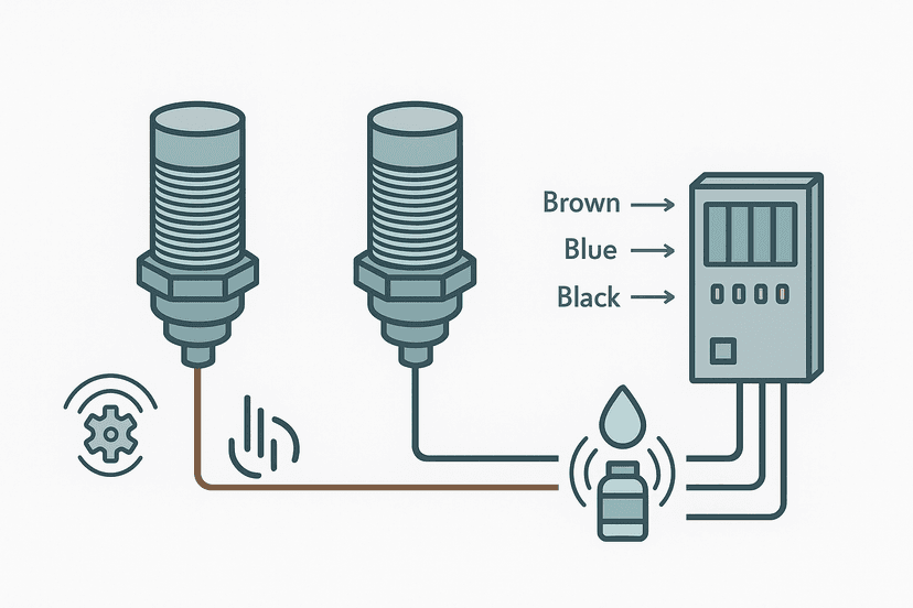
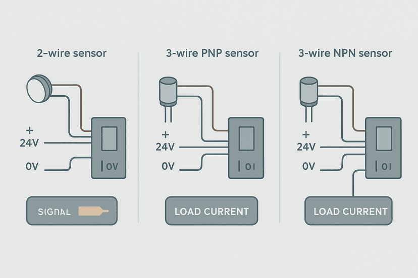
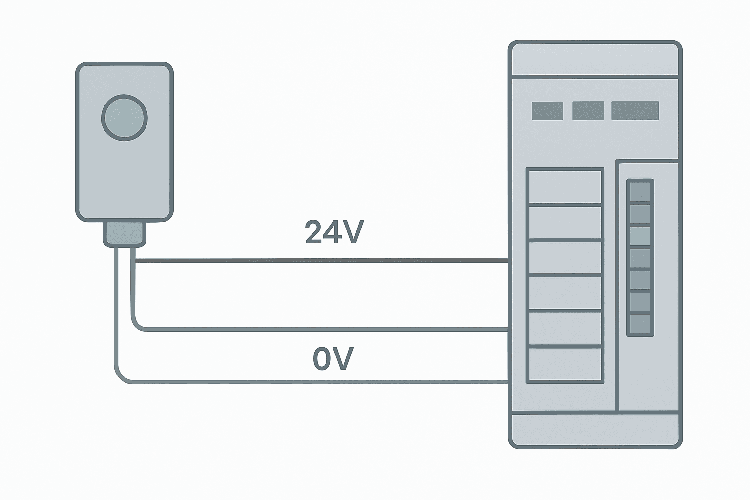
The industry standard wire colours for 3-wire DC sensors follow IEC 60947-5-2: brown to 24 VDC positive, blue to 0 V common, and black to the signal output. For a PNP sensor the black wire connects to the PLC input terminal. When the sensor detects a target, it pulls the black wire to approximately 24 V, which the PLC reads as logic 1. See the 3-wire sensor wiring guide for wiring diagrams of both polarities.
Keep the sensor cable away from motor power cables and VFD output cables. Photoelectric sensors are susceptible to electrical noise, especially the high-frequency switching noise from drives. Route sensor cables in a separate trunking and use shielded cable for runs over 5 m, grounding the shield at the panel end only. The post on shielding analog signal cables covers the grounding principle, and the same approach applies here.
Photoelectric Sensor PLC Ladder Logic Example
A through-beam sensor on a conveyor exit gate feeds an input tag. When the beam breaks (sensor output goes ON in dark-on mode), the PLC should latch a part-present flag, start a 500 ms verification timer to filter spurious pulses, and only count the part after the timer completes. This avoids false counts from vibration or a slow-moving part edge. You can try a similar debounce circuit yourself in the interactive debounce exercise.
Through-Beam Sensor: Verified Part Detection with TON Debounce (Studio 5000). Ladder logic (5 rungs): Rung 0: examine if Gate_PhotoEye is on (XIC), then TON on Eye_Verify. Rung 1: examine if Eye_Verify.DN is on (XIC), then examine if Part_Count_Latch is off (XIO), then examine if Count_OS is on (XIC), then CTU on Exit_Counter. Rung 2: examine if Exit_Counter.DN is on (XIC), then examine if Batch_DN_OS is on (XIC), then latch output Batch_Done_Latch (OTL). Rung 3: examine if Batch_Done_Latch is on (XIC), then examine if HMI_BatchReset is on (XIC), then unlatch output Batch_Done_Latch (OTU), then either RES on Exit_Counter. Rung 4: examine if Gate_PhotoEye is off (XIO), then RES on Eye_Verify. Gate_PhotoEye goes ON when the through-beam is broken (dark-on mode). A 500 ms TON filter confirms the detection is not a glitch. On timer completion, a one-shot increments the batch counter. The counter latches Batch_Done_Latch at preset. Clearing the beam resets the verify timer so the next part starts fresh. This prevents double-counting from a part pausing in the beam.
Alignment, Teach and Sensitivity Settings
Most modern photoelectric sensors have a multi-turn sensitivity potentiometer and a pair of indicator LEDs: one for power/output state, one for signal margin. During alignment you want the signal margin LED to be solid green (not flickering), which means the sensor is seeing the beam or the reflector with enough excess gain to handle lens contamination or slight misalignment over time. A flickering margin LED on day one means you will have nuisance faults within weeks.
Through-beam sensors need careful angular alignment. Most manufacturers spec a maximum angular deviation of plus or minus 3 to 5 degrees. On a long 20 m run that is still several centimetres of lateral tolerance at the receiver, but vibration from heavy machinery can walk the beam over time. Lock the mounts with thread-locking compound after alignment. I had a through-beam sensor on a press line that looked perfectly aligned at commissioning but dropped out every time the press cycled at full tonnage because the mount was bolted to the same frame as the press. Moving it to a free-standing post fixed it immediately.
Teach functions on diffuse and retro-reflective sensors let you set detection thresholds automatically by pressing a button with and without the target in place. This is far more reliable than manually turning the potentiometer and guessing. Use it.
Common Faults and How to Diagnose Them
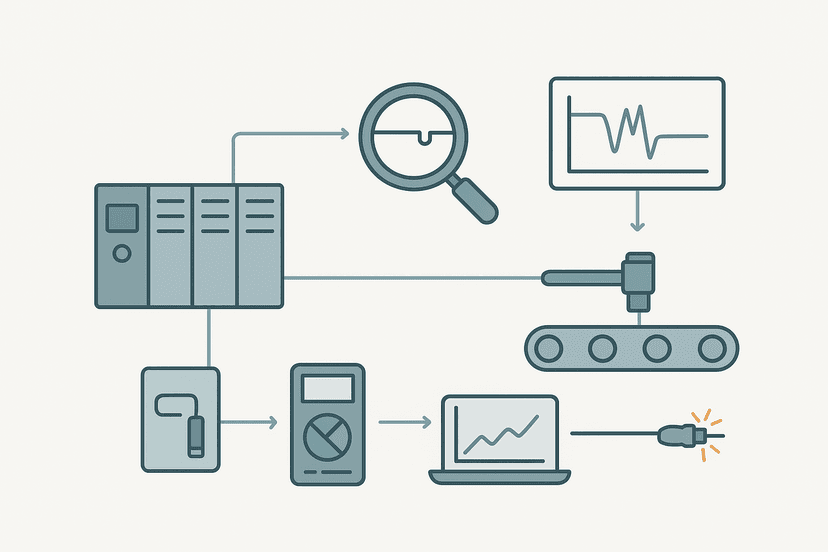
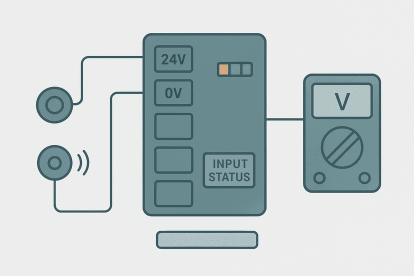
Intermittent sensor faults on photoelectric sensors almost always trace back to one of four causes: dirty or fogged optics, marginal sensing distance or alignment, electrical noise, or a wiring connection that has vibrated loose. The post on intermittent sensor fault troubleshooting has a systematic method that applies directly. For suspected wiring issues, the PLC digital input fault diagnosis guide walks you through multimeter checks at the input terminal.
- Output always ON regardless of target: check L.O./D.O. selection, verify the beam path is not permanently blocked or the reflector is missing.
- Output never ON: check 24 V supply to sensor (brown wire), verify NPN/PNP match to input module, measure black wire voltage when target is present.
- Random false triggers: look for ambient light sources (sunlight through a window, another sensor cross-talking), and check cable routing near VFD output cables.
- Stable during setup but fails in production: usually thermal expansion shifting alignment, or lens contamination from coolant mist or dust.
- PLC input LED flickers but logic does not see it: the signal duration may be shorter than the PLC scan time. Add a TON debounce timer in logic or use a sensor with output pulse stretching. See how the PLC scan cycle works for why this matters.
Choosing Between a Photoelectric and a Proximity Sensor
Inductive proximity sensors are simpler, cheaper and extremely resistant to noise and contamination, but they only detect ferrous (and some non-ferrous) metals at short range, typically 2 to 20 mm. Capacitive proximity sensors extend that to non-metals and liquids, still at short range. Photoelectric sensors detect any material, at much longer distances, with no contact. The tradeoff is that photoelectrics need clean optics and careful alignment. If your target is a steel part at 5 mm range in a dirty environment, an inductive proximity sensor wins every time. If it is a plastic bottle at 300 mm, a diffuse photoelectric is the right tool. The inductive vs capacitive proximity sensor comparison covers the proximity side in depth.
For PLC wiring mechanics, photoelectric sensors wire identically to proximity sensors: 3-wire or 4-wire, same 24 VDC supply, same PNP/NPN output to the digital input module. If you already know how to wire a proximity sensor to a PLC from the proximity sensor wiring guide, you already know how to wire a photoelectric sensor. The physics differ; the wiring does not.
IO-Link Photoelectric Sensors
An increasing number of photoelectric sensors now ship with IO-Link ports alongside the standard discrete output. IO-Link lets the PLC read signal strength, temperature, operating hours and error codes from the sensor over a single unshielded cable, and set parameters like sensitivity and threshold remotely without touching the sensor. This is genuinely useful on hard-to-reach mounting positions. If you are specifying new hardware and your PLC supports IO-Link masters, it is worth the small cost premium. The IO-Link explained guide covers how the master/device architecture works and how the data maps into the PLC.
What to Read Next
If you want to go deeper on sensor wiring to PLC inputs, start with the 3-wire PNP vs NPN wiring guide and then the proximity sensor wiring to a PLC complete guide which shows terminal-level diagrams for several PLC families. To see a real counter application that uses a photoelectric sensor as the trigger, the PLC bottle filling machine project walks through a full ladder logic program. And if you want to practice counting parts from a sensor signal yourself, open the batch counting exercise in the interactive ladder editor and toggle the inputs to see the CTU in action.
Frequently asked questions
What is a photoelectric sensor used for in a PLC system?
What is the difference between through-beam, retro-reflective and diffuse photoelectric sensors?
Do photoelectric sensors output NPN or PNP signals?
What voltage do photoelectric sensors run on?
Why does my photoelectric sensor trigger intermittently?
Can a photoelectric sensor detect clear or transparent objects?
What is background suppression in a diffuse photoelectric sensor?
How far can a photoelectric sensor detect?
Does a photoelectric sensor need a separate power supply from the PLC?
How do I wire a 3-wire PNP photoelectric sensor to a PLC input?
Now build it
You have just read about TON. Reading a rung and making one behave are different skills, and the second one is the job.
Flasher
Intermediateabout 15 minTwo timers chained in a loop make a lamp blink: the classic two-TON flasher used for warning beacons everywhere. Your first taste of timers driving each other.
Build this rungFree, no signup, runs in your browser. See all 16 exercises.
Was this helpful?