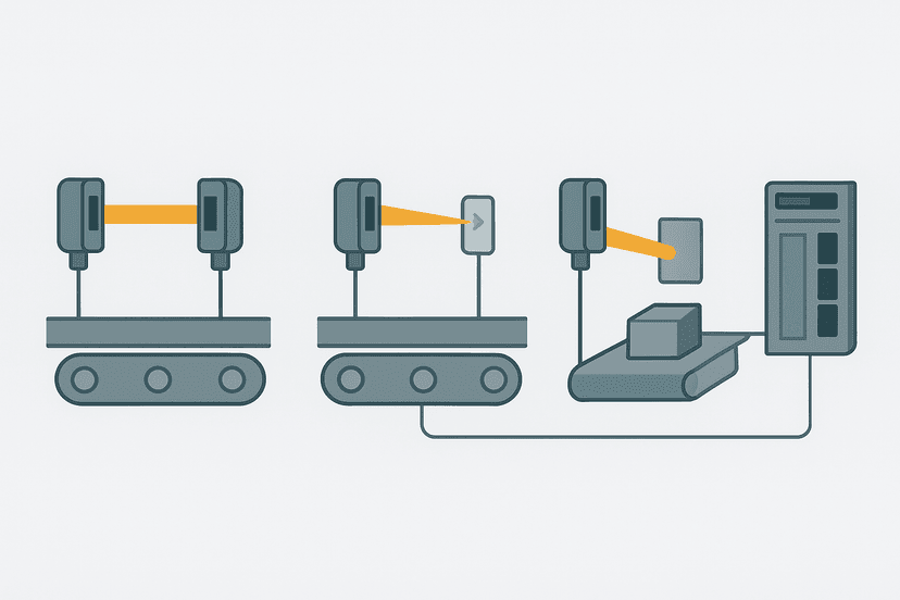
4-Wire Proximity Sensor Wiring to a PLC
If you have ever opened a sensor bag and counted four wires instead of three, you already know the moment of mild confusion that follows. A 4-wire proximity sensor is not complicated, but it does behave differently from the 3-wire version most engineers wire daily. Get it wrong and you will either damage the output transistor or wire up the wrong logic polarity and spend an afternoon wondering why your machine does the opposite of what you programmed.
What Is a 4-Wire Proximity Sensor?
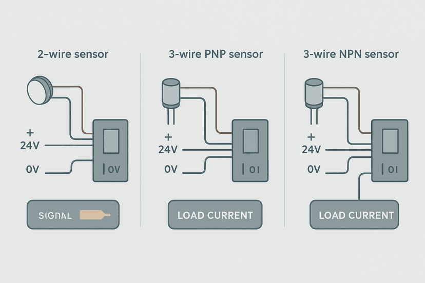
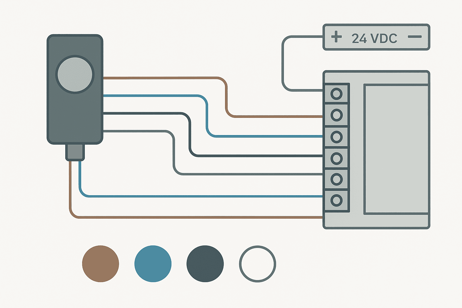
A 4-wire proximity sensor has two power wires and two independent signal outputs from a single sensing element: one normally open (NO) output and one normally closed (NC) output. Both outputs are driven by the same internal switching transistor. You get four conductors total: positive supply, negative supply, NO output, and NC output. This is the core difference between a 3-wire sensor, which gives you one output (your choice of NO or NC at order time), and a 4-wire sensor, which gives you both simultaneously on separate wires.
4-Wire Proximity Sensor Wire Colors and Their Functions
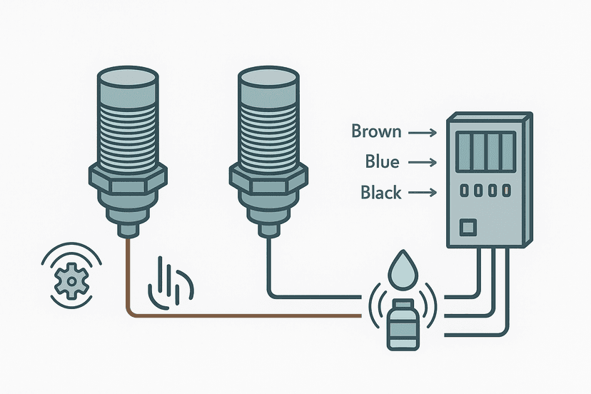
The IEC 60947-5-2 color convention for DC proximity sensors is consistent across most manufacturers. Stick to this table and you will rarely go wrong, but always cross-check with the specific sensor datasheet before you start stripping wire.
| Wire Color | Function | Connect To |
|---|---|---|
| Brown | Positive supply (24 VDC) | 24 VDC rail or fused supply |
| Blue | Negative supply (0 V) | DC common / 0 V rail |
| Black | Output 1, normally open (NO) | PLC input terminal (or leave insulated) |
| White | Output 2, normally closed (NC) | PLC input terminal (or leave insulated) |
PNP vs NPN: Which 4-Wire Sensor Do You Have?
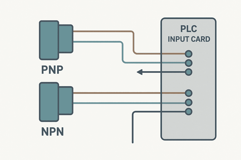
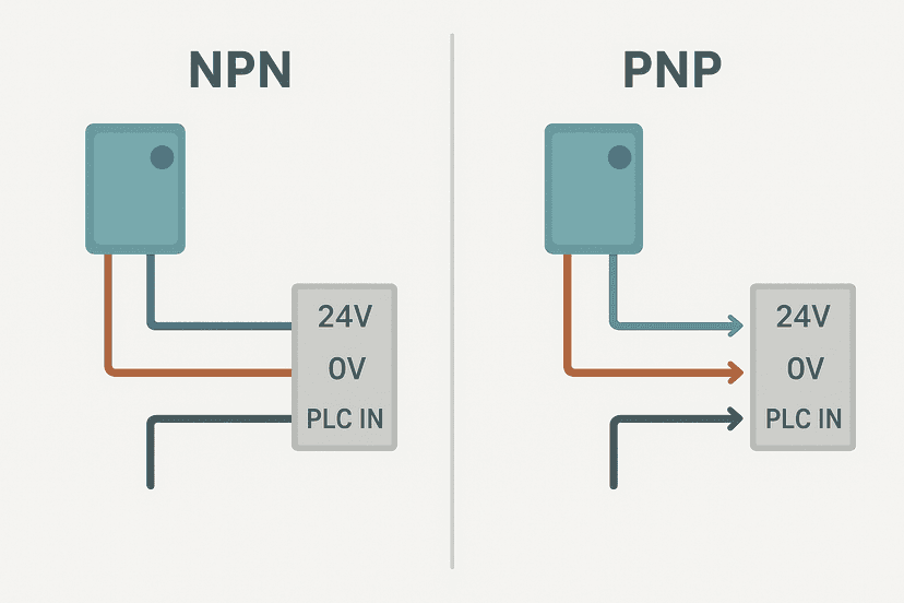
Like 3-wire sensors, 4-wire proximity sensors come in PNP (sourcing) and NPN (sinking) variants. The wire colors are identical between them, which is a common source of confusion. The difference is in how the output transistor switches. For a deeper comparison of these two types, see NPN vs PNP Sensors: Wiring and PLC Connection.
| Sensor Type | Output Active State | Compatible PLC Input | Current Flow Direction |
|---|---|---|---|
| PNP (sourcing) | Output pulls toward +24 V when active | Sinking / NPN input module | Sensor to PLC input to 0 V |
| NPN (sinking) | Output pulls toward 0 V when active | Sourcing / PNP input module | +24 V to PLC input to sensor |
In Europe and most of Asia, PNP sensors dominate the market for 24 VDC systems. In North America you will still find a mix, but PNP is increasingly the default. If you are working on a legacy machine with NPN sensors and a sourcing input card, check out Sinking vs Sourcing PLC I/O: Wiring It Right before you start reterminating anything.
How to Wire a 4-Wire PNP Proximity Sensor to a PLC Input
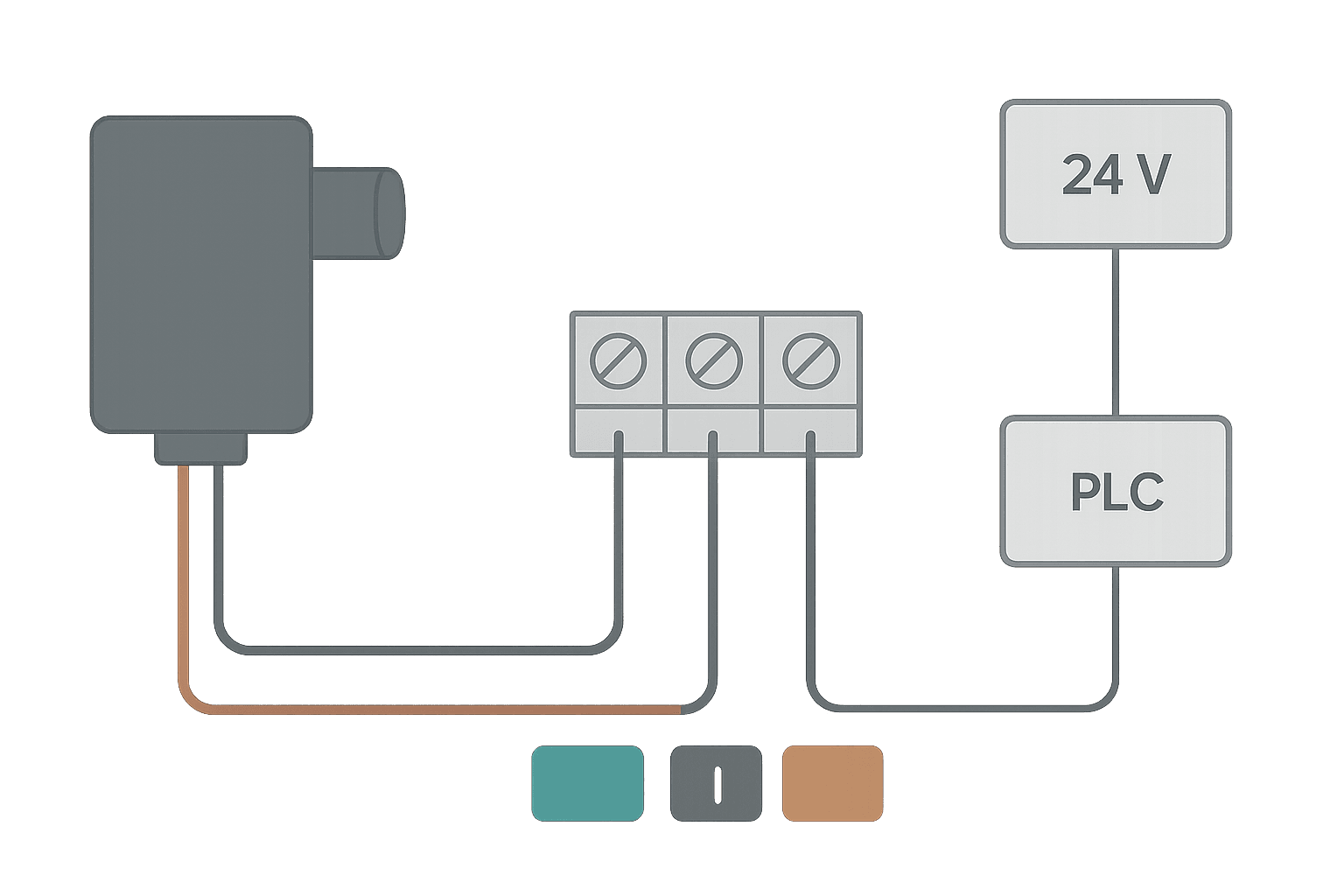
This is the most common scenario in modern plants. You have a PNP 4-wire sensor and a standard sinking digital input module. Here is the step-by-step connection:
- Connect the brown wire to the fused +24 VDC supply. Use a 0.5 A fast-blow fuse per sensor if your panel design calls for individual protection.
- Connect the blue wire to the DC common (0 V) rail.
- Decide which output you need. For a standard detection signal, use the black (NO) wire. For a guarding or safety interlock application, use the white (NC) wire.
- Run the chosen output wire to the PLC input terminal. The PLC input module's common terminal connects to 0 V (sinking input configuration).
- Insulate the unused output wire with heat-shrink or a terminal ferrule cap. Do not leave it bare.
- Verify with a multimeter: with no target present, the NO black wire should read 0 V at the PLC terminal. Bring a metal target within sensing range and it should rise to roughly 23 to 24 VDC. The NC white wire does the opposite.
How to Wire a 4-Wire NPN Proximity Sensor to a PLC Input
NPN 4-wire wiring flips the reference. The output transistor pulls toward 0 V when active, so you need a sourcing input module whose common terminal sits at +24 VDC.
- Connect brown to +24 VDC.
- Connect blue to 0 V.
- Run the chosen output wire (black for NO, white for NC) to the PLC input terminal.
- Connect the PLC input module's common terminal to +24 VDC (sourcing configuration).
- Insulate the unused output wire.
- Test: with no target, the NO (black) output reads +24 V at the input terminal. With target present it drops toward 0 V, which registers as logic ON for a sourcing input.
When to Use Both Outputs Simultaneously
The whole point of paying for a 4-wire sensor is using both outputs when your application needs it. Here are the two main cases where that earns its cost back.
Dual-Channel Safety Monitoring
Wire the NO output to one PLC input and the NC output to a second PLC input. In your ladder logic, you can then verify that one input is always the complement of the other. If both inputs read the same state simultaneously, you have detected a broken wire, a welded transistor, or a short circuit. This cross-check pattern is common in machinery where you want some level of sensor integrity monitoring, though it does not by itself meet the requirements of a full safety-rated function. For safety-rated applications, refer to ISO 13849-1 PL Levels: What They Mean in Practice and use a proper safety relay or safety PLC. You can also review Safety Relay Wiring: Circuits Explained for typical circuit architectures.
Single Sensor, Two Logic Functions
The more common everyday use: you need the NO output to enable a conveyor when a part is present, and you need the NC output to hold a gate open when no part is present. One sensor body, one mounting bracket, one cable run. That is cleaner and cheaper than two 3-wire sensors mounted side by side. I have used this arrangement on a rotary indexer where space was genuinely tight and a second sensor would have required a completely new bracket fabrication.
Common Wiring Mistakes and How to Avoid Them
- Shorting both outputs together: never bridge the black and white wires. They are driven by the same transistor, and shorting them causes an internal short circuit that kills the output stage instantly.
- Wrong common on the PLC module: PNP sensor into a sourcing input module, or NPN sensor into a sinking input module, will not trigger the input correctly. Check the module wiring diagram before you connect anything.
- Forgetting to insulate the spare wire: a bare wire flapping around inside a panel is a short circuit waiting to happen, especially in a vibrating machine enclosure.
- Confusing NO and NC at commissioning: if your logic is inverted and the machine runs when it should stop, swap from the black wire to the white wire at the terminal block rather than inverting logic in the program. Keep the hardware and software consistent.
- Voltage drop on long cable runs: a 50 m cable with 0.5 mm2 conductors can drop 1 to 2 VDC at 100 mA, pulling the sensor supply below its minimum. Use 0.75 mm2 or thicker for runs beyond 20 m. For panel wiring fundamentals, Control Panel Wire Routing and Segregation covers the sizing and routing principles.
Ladder Logic for a 4-Wire Sensor Diagnostic Rung
When you wire both outputs to separate PLC inputs, you can add a simple diagnostic rung that latches a fault if both inputs ever match state. This rung uses Studio 5000 tag names but the logic pattern works on any platform. The XOR logic below relies on the fact that NO and NC should always be opposite: if they are both ON or both OFF at the same time, something is wrong with the sensor or its wiring.
4-Wire Sensor Diagnostic: NO/NC Complement Check with Fault Latch. Ladder logic (4 rungs): Rung 0: examine if Prox_NO_Input is on (XIC), then examine if Prox_NC_Input is on (XIC), then examine if BothON_OS is on (XIC), then latch output Prox_Wire_FaultLatch (OTL). Rung 1: examine if Prox_NO_Input is off (XIO), then examine if Prox_NC_Input is off (XIO), then examine if BothOFF_OS is on (XIC), then latch output Prox_Wire_FaultLatch (OTL). Rung 2: examine if Prox_Wire_FaultLatch is on (XIC), then energize output HMI_SensorFaultAlarm (OTE). Rung 3: examine if Prox_Wire_FaultLatch is on (XIC), then examine if HMI_SensorFaultAck is on (XIC), then examine if Prox_NO_Input is off (XIO), then examine if Prox_NC_Input is off (XIO), then unlatch output Prox_Wire_FaultLatch (OTU). Rung 1 fires a one-shot and latches the fault if both NO and NC inputs are ON simultaneously (output transistor welded or wiring fault). Rung 2 does the same if both are OFF simultaneously (open circuit or broken wire). Rung 3 drives the HMI alarm bit. Rung 4 allows operator acknowledge only when both inputs have returned to a complementary state, preventing a nuisance reset while the fault condition persists.
This pattern is a lightweight wire-break and short-circuit check. It is not a substitute for a certified safety function, but it catches the most common field failures: a severed cable (both inputs go OFF) or a stuck output (both inputs match). For more on diagnosing sensor faults in the field, Intermittent Sensor Faults: How to Find Them is worth bookmarking.
Checking Your Wiring with a Multimeter
Before you commission, spend two minutes with a multimeter before the PLC is powered. With 24 VDC applied to brown and blue only, measure the voltage on each output wire relative to 0 V with no target present. A PNP NO output (black) should read less than 1 VDC. A PNP NC output (white) should read 22 to 24 VDC. Bring a steel target within the rated sensing range and the readings should swap. If they do not, the sensor is either wired backwards (brown/blue reversed) or faulty. A full step-by-step process for testing inputs once the sensor is connected is covered in How to Test a PLC Input: Step-by-Step Guide and PLC I/O Fault Diagnosis with a Multimeter.
Selecting the Right Output for Your Application
For most conveyor and part-detection applications, wire the black (NO) output. Your ladder logic then uses an XIC contact on that input: no part, no current, contact open, machine waits. Part present, output switches, contact closes, machine runs. Clean and intuitive. Use the white (NC) output when you need a normally energized circuit that de-energizes on detection, which is common for guard monitoring and interlock circuits. The 3-Wire Sensor Wiring: PNP vs NPN to PLC Inputs article goes into the logic convention in more detail if you want to understand why NC contacts are preferred in some safety-related rungs. You should also understand the difference between NO vs NC Contacts in PLC Ladder Logic before deciding which output to use.
Keep Learning
Now that you have the 4-wire wiring sorted, there are a few natural next steps. If you want to understand how inductive and capacitive proximity sensors differ in sensing technology and application, Inductive vs Capacitive Proximity Sensors: Full Guide covers that in depth. For the full wiring picture including 2-wire and 3-wire sensors in a single reference, Proximity Sensor Wiring to a PLC: Full Guide is the complete companion. And if you want to practice the diagnostic fault latch logic from this article in a live ladder editor without any hardware, open the interactive set-reset exercise to get hands-on with OTL and OTU coils before you apply them to a real machine.
Frequently asked questions
What is the difference between a 3-wire and 4-wire proximity sensor?
What are the wire colors on a 4-wire proximity sensor?
Can I connect both the NO and NC outputs of a 4-wire sensor to the PLC at the same time?
What happens if I leave the unused output wire unconnected?
Does a 4-wire proximity sensor work with both sinking and sourcing PLC inputs?
How do I know which output is NO and which is NC without a label?
Why would I choose a 4-wire sensor over a 3-wire sensor?
Can I wire the NO and NC outputs in series or parallel?
What is the maximum cable length for a 4-wire proximity sensor to a PLC?
Do 4-wire proximity sensors need a load resistor?
Now build it
You have just read about OTL and OTU. Reading a rung and making one behave are different skills, and the second one is the job.
Set / Reset
Beginnerabout 8 minLatch and unlatch instructions (OTL / OTU) instead of a seal-in branch, and the crucial detail of which one wins when both fire, decided purely by rung order.
Build this rungFree, no signup, runs in your browser. See all 16 exercises.
Was this helpful?