Allen-Bradley PLC Interview Questions: Real Answers
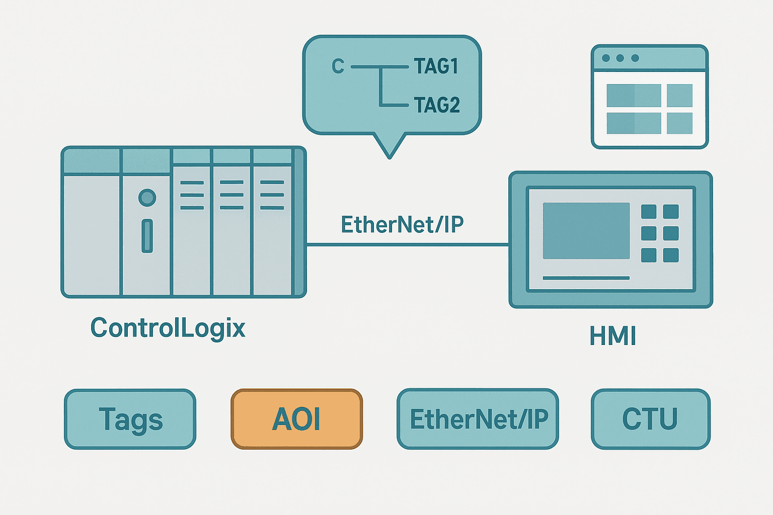
Allen-Bradley PLC roles are some of the most in-demand positions in North American automation. Interviewers for these jobs expect you to know Studio 5000 specifically, not just generic PLC theory. The questions below reflect what actually gets asked in technical screenings and face-to-face interviews, from entry-level integrator positions through senior controls engineer roles.
What Are Allen-Bradley PLC Interview Questions?
Allen-Bradley PLC interview questions are technical questions that test a candidate's knowledge of Rockwell Automation hardware (ControlLogix, CompactLogix, MicroLogix), the Studio 5000 Logix Designer software environment, tag-based addressing, EtherNet/IP networking, ladder logic instructions and troubleshooting methods. They are asked in interviews for controls engineer, automation technician and systems integrator roles where Rockwell Automation equipment is the primary platform.
Hardware and Platform Questions
1. What is the difference between ControlLogix and CompactLogix?
ControlLogix is a modular chassis-based system. You pick a chassis size (4, 7, 10, 13 or 17 slots), then populate it with a 1756-L8x CPU, a power supply and whichever 1756-series I/O and communication modules you need. You can also link multiple chassis with a 1756-EN2T bridge, which lets a single program control thousands of I/O points across several racks. CompactLogix (1769-L3x) integrates the power supply and CPU in one compact unit and uses 1769-series I/O that snaps directly onto the side. It tops out at 30 local I/O modules and is the right call for standalone machines. Both platforms run the same Studio 5000 software and the same tag-based programming model.
2. What is the Logix 5000 tag database and why does it matter?
Every variable in a Studio 5000 project lives in the tag database rather than at a fixed numeric memory address. Tags have a name, a data type and a scope (controller-scope tags are global; program-scope tags are local to one program). This matters because you reference a signal by what it means, like Pump1_RunFB, not by where it happens to live in memory. It makes programs readable, and it means moving a signal to a different I/O slot only requires updating the tag's physical assignment, not hunting through thousands of rungs. For a deeper look at addressing approaches across platforms, see PLC Addressing Modes: Direct, Indirect and Symbolic.
3. What task types exist in a Studio 5000 project?
Studio 5000 supports three task types. A continuous task runs forever in a loop and is the default home for most machine logic. A periodic task runs on a fixed interval (1 ms to 2000 s) and pre-empts the continuous task when its time comes. An event task fires on a hardware interrupt or a software trigger such as an axis event. You can have one continuous task, up to 15 periodic or event tasks, and each task can hold multiple programs. The scan cycle post at How the PLC Scan Cycle Works: Step by Step explains the underlying execution model well.
Studio 5000 Programming Questions
4. What is an Add-On Instruction and when would you create one?
An Add-On Instruction (AOI) is a custom reusable instruction you build from standard Logix instructions. You define input, output and in-out parameters plus local tags, then write the logic inside. When you call the AOI in a rung, you pass real tags to its parameters just like you would with a native TON or CTU. The typical use case is repeated equipment: a conveyor drive AOI, a valve AOI, a PID loop wrapper. Define it once, call it 40 times. Changes to the AOI definition propagate everywhere it is used after a download. On larger projects this is the single biggest maintainability tool available.
5. Explain the difference between OTE, OTL and OTU
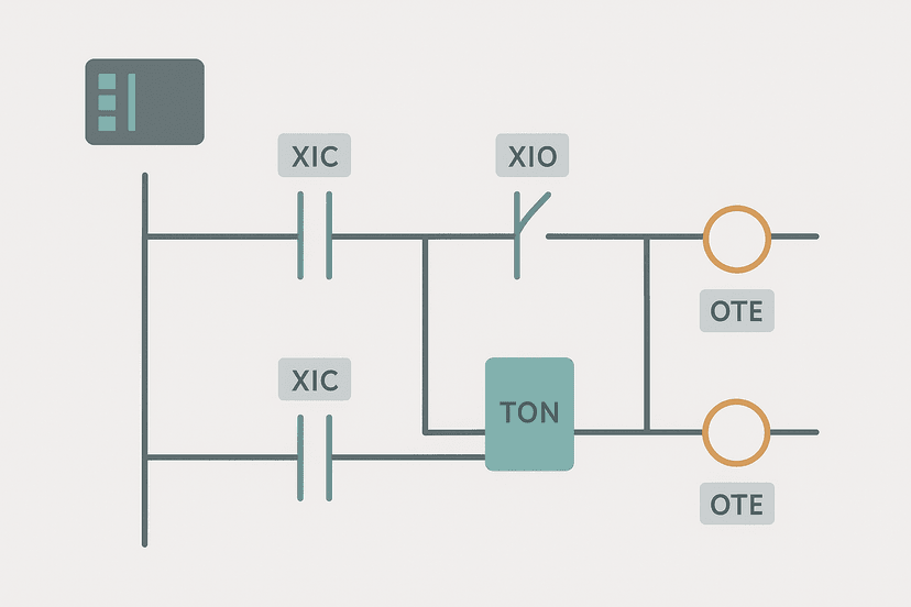
OTE (Output Energize) is non-retentive: the bit is 1 only while the rung condition is true. The moment the rung goes false, the bit clears. OTL (Output Latch) sets a bit to 1 and holds it regardless of rung state. OTU (Output Unlatch) clears that same bit. You need OTL/OTU any time an output must stay active after the triggering condition disappears, such as an alarm latch or a mode bit. The full breakdown with examples is in OTL and OTU Latch Coils in Ladder Logic Explained.
6. What is the OSR instruction and why can't you put it on the same rung twice?
OSR (One-Shot Rising) detects the rising edge of the rung condition and passes power for exactly one scan. It uses a storage bit to remember the previous rung state. If you put two OSR instructions on the same rung using the same storage bit, they fight each other and neither works correctly. Each OSR needs its own unique storage bit. You almost always want a one-shot when incrementing a counter from a physical sensor, so the counter does not accumulate every scan while the sensor is active. See One-Shot Rising Edge in Ladder Logic: OSR Explained for the full picture.
7. How does indirect addressing work in Studio 5000?
You put a tag name inside the array brackets: RecipeValues[Recipe_Index]. When Recipe_Index equals 2, the instruction reads element 2. When it equals 5, it reads element 5. This is how step sequencers work in Logix: store output words in an array, use a counter accumulator as the index, and the active output pattern changes automatically as the counter steps. One gotcha: if the index tag goes out of range (past the last element), the controller throws a major fault. Always clamp or validate the index before using it. The PLC Addressing Modes post covers this in detail.
8. What data types would you use for a 4-20 mA analog input in Studio 5000?
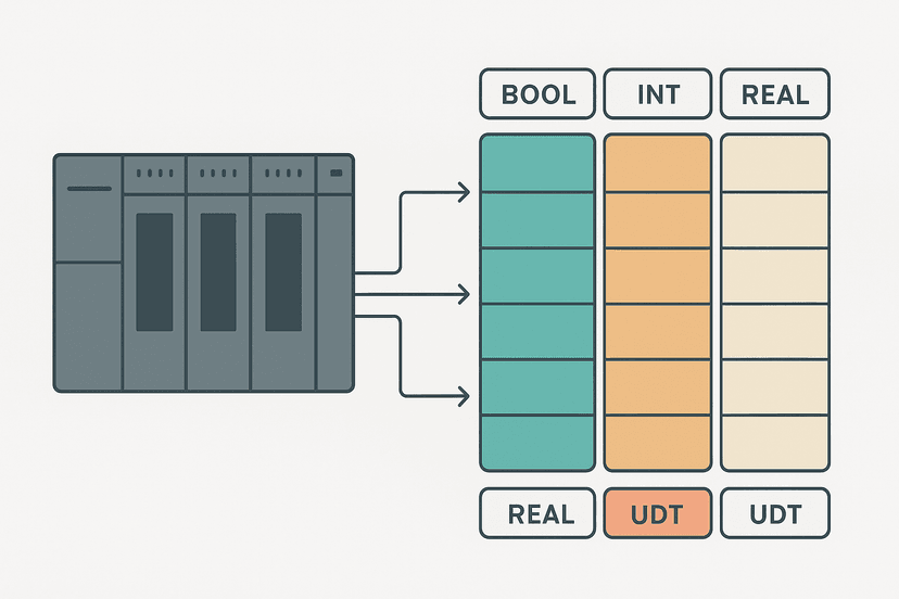
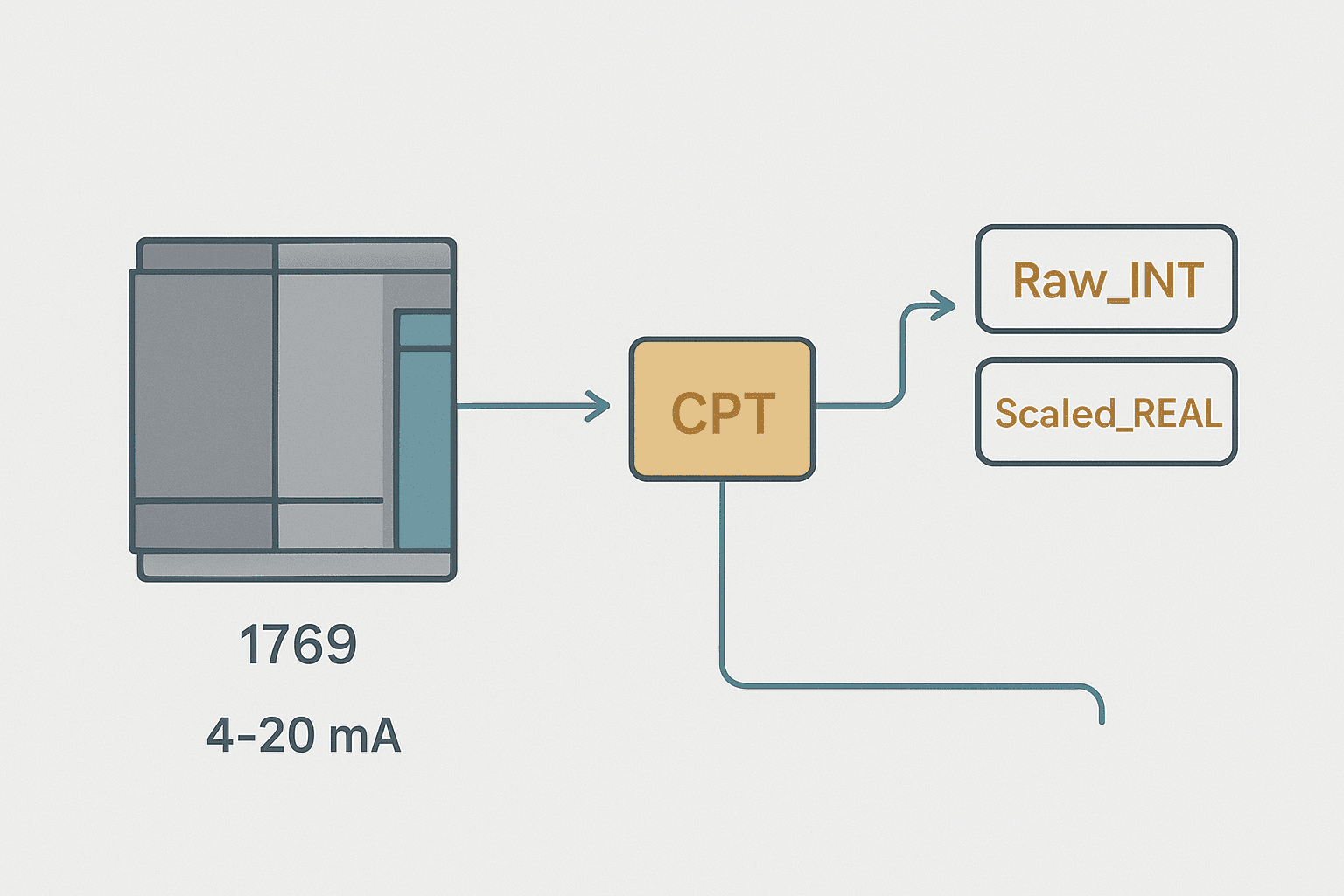
The raw count from a 1756-IF16 or 1769-IF4 analog input module is an INT (16-bit signed integer), typically scaling 4 mA to 6242 counts and 20 mA to 31208 counts for the default unipolar range. For engineering-unit values you would use REAL (32-bit floating point) after applying a scaling calculation. In practice I always store the raw count in an INT tag and the scaled value in a REAL tag, then use a Compute (CPT) instruction or a structured-text expression to do the math. The 4-20 mA Scaling Formula post has the exact equation.
9. How do you handle a major fault in a ControlLogix controller?
A major fault stops the controller and sets the CPU LED to red. You connect online in Studio 5000, go to Controller Properties, then the Faults tab, read the fault code and subcode, then clear the fault. Common causes include an array index out of range, a divide-by-zero, or a module communication loss. You can also write a major fault routine in the Controller Properties that runs when a major fault occurs, which lets you log the fault code to a tag and attempt a controlled safe state before the controller halts. For a systematic approach to CPU-level faults, see PLC CPU Faults: How to Diagnose Them Step by Step.
10. What is the difference between a global tag and a program-scope tag?
Controller-scope (global) tags are visible to every program and routine in the project, including produced/consumed tag links and HMI connections. Program-scope tags are only visible inside the program that owns them. Use program-scope tags for internal working bits and intermediate values that no other program or the HMI needs to see. It keeps the global tag list clean and prevents accidental cross-program interaction. A mistake I see constantly on inherited projects: everything is global, the tag list has 4000 entries, and nobody can find anything.
EtherNet/IP and Networking Questions
11. What is the difference between implicit and explicit messaging in EtherNet/IP?
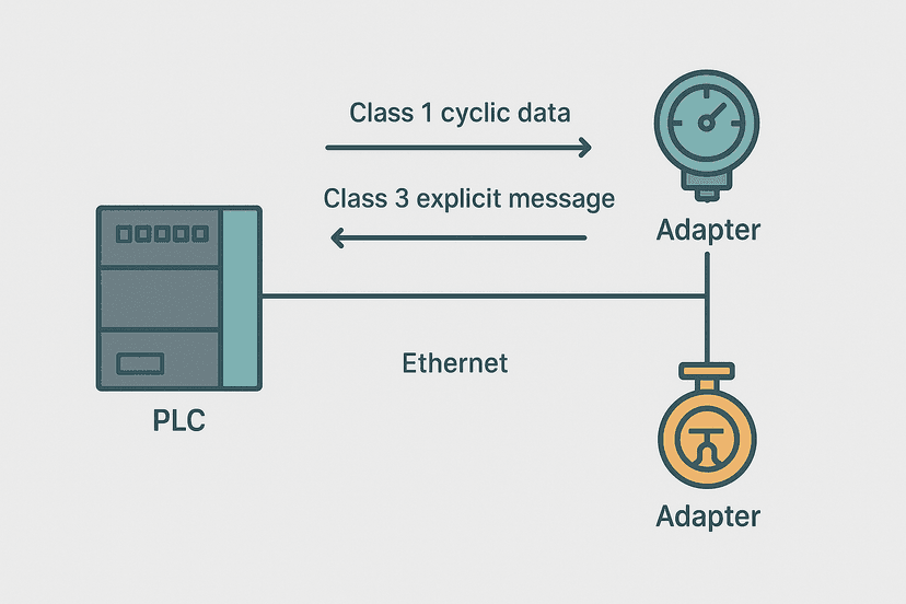
Implicit messaging is the real-time, cyclic I/O connection. The controller and device establish a connection with a fixed requested packet interval (RPI) and exchange data every cycle without the CPU having to request it. This is how remote I/O adapters and drives send their status and receive their commands. Explicit messaging is on-demand: the controller sends a MSG instruction to read or write a specific parameter when the ladder logic calls for it. Drive parameter reads, recipe downloads and inter-PLC data exchanges typically use explicit messaging. The EtherNet/IP Scanner vs Adapter post explains the connection model in full.
12. What is a produced and consumed tag?
A produced tag is a controller-scope tag in one ControlLogix that is broadcast over the backplane or EtherNet/IP network. Another ControlLogix subscribes to it with a consumed tag. The two tags stay synchronized at the RPI you configure, with no MSG instruction needed. This is the cleanest way to share real-time data between two PLCs on the same line, for example a press controller sharing its cycle state with a conveyor controller. Both controllers must be on the same EtherNet/IP network and must know each other's IP addresses.
13. What happens to remote I/O outputs when the network connection drops?
Each output module has a configurable communication fault action in Studio 5000 under the module's properties: go to zero (de-energize all outputs), hold last state, or go to a user-defined fault value. The default is go to zero, which is the safest choice for most applications. You must think through this per module at design time, not during commissioning. A valve that holds its last state during a comms fault might be exactly right for one application and a safety hazard for another. For diagnosis when this happens in the field, see EtherNet/IP Communication Loss: How to Diagnose It.
14. How do you configure a MSG instruction for a peer-to-peer data read?
Drop a MSG instruction on a rung. In the message configuration: set the message type to CIP Data Table Read (or Write), enter the source tag path in the remote controller, set the number of elements, and point the destination to a local tag array of the correct data type. In the Communication tab, enter the path to the remote controller (typically the Ethernet module slot followed by the IP address). The MSG instruction is edge-triggered so you usually gate it with an OSR or a periodic timer done bit, not a continuous contact, to avoid flooding the network with requests.
Troubleshooting and Commissioning Questions
15. How do you go online with a ControlLogix without overwriting the controller program?
Open Studio 5000, choose Go Online from the Communications menu, and select your controller. If the project on disk does not match what is in the controller, Studio 5000 warns you. You can upload from the controller (which copies the controller's program to your PC), or you can go online read-only to observe without risk. Never choose Download unless you intentionally want to replace the controller program. I always upload first on an unfamiliar machine to get a current copy, then go online to monitor.
16. How do you use cross-referencing in Studio 5000 to find every use of a tag?
Right-click the tag in the tag database and choose Cross Reference, or use the Logic menu and select Cross Reference. Studio 5000 lists every routine and rung where that tag appears as an input, output or parameter. This is essential when troubleshooting a bit that seems to be set by something unexpected. On a project with 200 routines, hunting manually is not viable. Cross-reference is the first thing I use when a machine behaves in a way the obvious logic does not explain.
17. A digital output is energized in the tag database but the field device is not moving. What do you check?
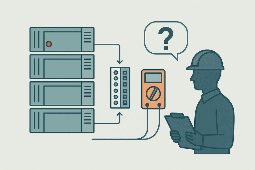
First, confirm whether the output module LED for that point is on. If the LED is off, the issue is between the tag and the module (forces, fault state, wrong slot in the path). If the LED is on, the problem is downstream: wiring, fuse, relay contact, or the field device itself. Use a multimeter to check voltage at the output terminal. The PLC Output Faults: How to Diagnose Them Fast post walks through this exact sequence. Also check for active forces on the tag since forced outputs ignore the program logic.
18. What is a program-mode fault and a run-mode fault in ControlLogix?
A run-mode fault occurs while the controller is scanning and executing logic. It typically stops the controller. A program-mode fault happens during a download or when the controller enters program mode and finds a configuration error. The fault type code in the Faults tab tells you which category you are in. Type 4 faults are usually I/O faults; type 7 faults are typically program faults such as illegal instruction use or corrupt routine data.
19. How do you use the trend tool in Studio 5000 for diagnostics?
In Studio 5000, go to Tools then Trends. Add the tags you want to watch (analog values, timer accumulators, bit tags), set the sample rate and time window, and start the trend while online. It is not a data historian but it is fast enough to catch a valve that bounces, a sensor that glitches, or a timer that is not reaching its preset. For analog input problems, trending the raw INT and the scaled REAL side by side immediately shows whether the issue is in the field signal or the scaling math. The PLC Troubleshooting with Online Monitoring article covers this workflow.
A Practical Duty-Standby Pump Alternation Rung
Interviewers often ask you to sketch or explain a real circuit on the spot. Duty-standby pump alternation is a classic Allen-Bradley application: run pump A until its runtime exceeds pump B's by a set amount, then swap duty. Here is a compact version that shows the alternation logic and a standby fault guard.
Duty-Standby Pump Alternation with TONR Runtime Tracking (Studio 5000). Ladder logic (13 rungs): Rung 0: examine if Sys_PumpDemand is on (XIC), then examine if PumpA_FaultLatch is off (XIO), then examine if Duty_Is_B is off (XIO), then latch output PumpA_Run (OTL). Rung 1: examine if Sys_PumpDemand is on (XIC), then examine if PumpB_FaultLatch is off (XIO), then examine if Duty_Is_B is on (XIC), then latch output PumpB_Run (OTL). Rung 2: examine if PumpA_Run is on (XIC), then TONR on PumpA_RunTimer. Rung 3: examine if PumpB_Run is on (XIC), then TONR on PumpB_RunTimer. Rung 4: examine if PumpA_RunTimer.ACC is on (XIC), then GRT on PumpA_RunTimer.ACC, then examine if PumpA_FaultLatch is off (XIO), then examine if Swap_OS is on (XIC), then latch output Duty_Is_B (OTL). Rung 5: examine if PumpB_RunTimer.ACC is on (XIC), then GRT on PumpB_RunTimer.ACC, then examine if PumpB_FaultLatch is off (XIO), then examine if SwapBack_OS is on (XIC), then unlatch output Duty_Is_B (OTU). Rung 6: examine if PumpA_Run is on (XIC), then examine if PumpA_RunFB is off (XIO), then TON on PumpA_StartTO. Rung 7: examine if PumpA_StartTO.DN is on (XIC), then examine if PumpA_RunFB is off (XIO), then examine if PumpA_Fault_OS is on (XIC), then latch output PumpA_FaultLatch (OTL). Rung 8: examine if PumpA_FaultLatch is on (XIC), then examine if HMI_FaultAck is on (XIC), then examine if PumpA_Run is off (XIO), then unlatch output PumpA_FaultLatch (OTU). Rung 9: examine if PumpB_Run is on (XIC), then examine if PumpB_RunFB is off (XIO), then TON on PumpB_StartTO. Rung 10: examine if PumpB_StartTO.DN is on (XIC), then examine if PumpB_RunFB is off (XIO), then examine if PumpB_Fault_OS is on (XIC), then latch output PumpB_FaultLatch (OTL). Rung 11: examine if PumpB_FaultLatch is on (XIC), then examine if HMI_FaultAck is on (XIC), then examine if PumpB_Run is off (XIO), then unlatch output PumpB_FaultLatch (OTU). Rung 12: examine if HMI_StopCmd is on (XIC), then unlatch output PumpA_Run (OTU), then either unlatch output PumpB_Run (OTU). PumpA runs as duty until its TONR accumulator exceeds PumpB's, then a one-shot sets Duty_Is_B and swaps roles. A 5-second start-timeout fault latch guards each pump. HMI acknowledge clears faults. TONR accumulators persist across power cycles so runtime equalization survives a restart.
If the interviewer asks how you would reset the TONR accumulators for planned maintenance, the answer is a separate rung with a RES instruction gated by an HMI maintenance-mode bit and an operator confirm. Never reset them automatically on every start or you lose the equalization benefit. You can practice retentive timer logic in the RTO runtime tracking exercise on this site.
Safety and Standards Questions
20. What is a GuardLogix controller and when is it required?
GuardLogix is Rockwell's safety-rated ControlLogix variant, certified to IEC 62061 SIL 2 and ISO 13849-1 PLd. It runs a standard ControlLogix CPU alongside a dedicated safety CPU that executes the safety task. The safety task is protected: you cannot modify it without a safety signature, and you cannot force safety tags from the standard side. You need GuardLogix (or Compact GuardLogix) when your risk assessment, done under ISO 13849-1 or IEC 62061, requires a certified safety function implemented in the PLC rather than in external safety relays.
21. How does a safety task differ from a standard task in Studio 5000?
The safety task runs at a fixed period you define (typically 10 ms to 500 ms) and cannot be interrupted by standard tasks. Safety tags are segregated: the standard program can read safety output tags but cannot write them. Any change to safety logic requires generating a new safety signature, which is a hash the controller checks on startup. If the signature does not match, the controller faults rather than run unverified logic. This is the architectural control that makes the safety task trustworthy.
Miscellaneous Questions That Trip People Up
22. What is the difference between TON, TOF and TONR in Studio 5000?
TON (Timer On Delay) starts timing when the rung goes true and resets when the rung goes false. TOF (Timer Off Delay) starts timing when the rung goes false after being true. TONR (Retentive Timer On Delay) accumulates time only while the rung is true and holds the accumulated value when the rung goes false, so it acts like a stopwatch. All three are covered in depth at TON, TOF and TONR Timers: What Actually Differs.
23. How do you scale a 4-20 mA analog input in ladder logic?
The standard linear scaling formula is: EU = (Raw - Raw_Min) / (Raw_Max - Raw_Min) * (EU_Max - EU_Min) + EU_Min. In Studio 5000 you either use a CPT (Compute) instruction with that expression, or you use the SCL (Scale) instruction which takes the raw value and four limit parameters and outputs the engineering-unit REAL. Both approaches are shown with real numbers in 4-20 mA Scaling in a PLC: ST and Ladder Code.
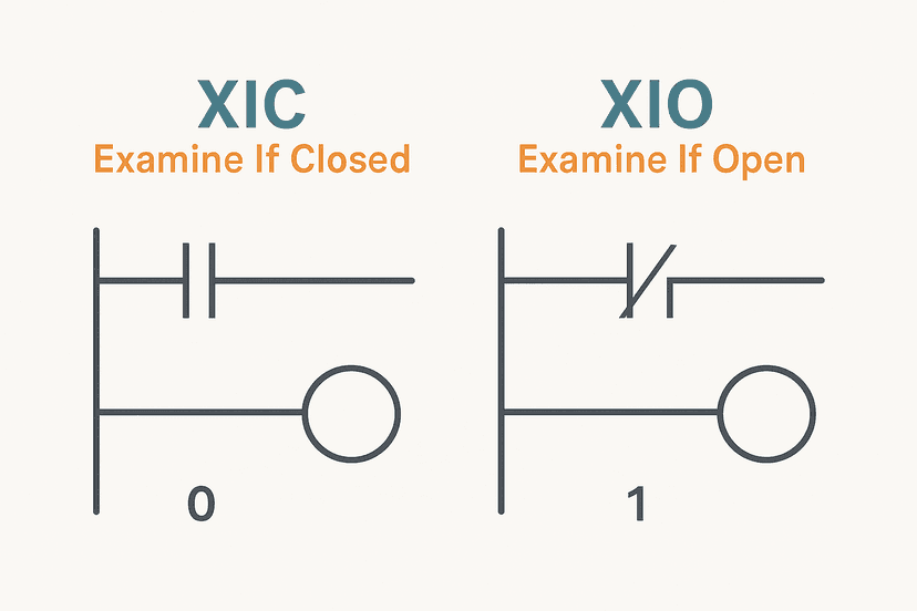
24. What is the difference between XIC and XIO?
XIC (Examine If Closed) passes power when the referenced bit is 1. XIO (Examine If Open) passes power when the referenced bit is 0. XIC is the normally-open contact; XIO is the normally-closed contact in ladder logic terms. The naming refers to the bit state, not the physical wiring of the field device. The distinction matters especially for safety circuits where a normally-closed physical input wired to fail-safe should use XIC in the ladder so that a broken wire (which de-energizes the input) opens the rung. See XIC vs XIO: Ladder Logic Contacts Explained for the full nuance.
25. How would you approach commissioning a new Studio 5000 project on a machine for the first time?
Start with the hardware configuration: confirm every module in Studio 5000 matches the physical chassis, slot for slot. Download and verify no I/O faults. Then do an I/O checkout in program mode: force each output one at a time, confirm field response, then verify each input by actuating the field device and watching the tag go true. Only after the I/O is verified do you run logic. Start in manual mode, test each output command, then switch to automatic. Keep a commissioning checklist and sign off each point. Never skip the I/O checkout; it is where most wiring errors surface. The PLC I/O Fault Diagnosis with a Multimeter post is a good reference for the test steps.
| Topic Area | Key Terms to Know | Depth Expected |
|---|---|---|
| Hardware | ControlLogix, CompactLogix, chassis, 1756/1769 modules | Intermediate |
| Tag System | Data types, scope, arrays, indirect addressing | Advanced |
| Instructions | XIC/XIO, OTE/OTL/OTU, OSR/OSF, TON/TOF/TONR, CTU/CTD | Advanced |
| AOI | Parameters, local tags, revision control, reuse | Intermediate |
| EtherNet/IP | Implicit vs explicit, produced/consumed tags, MSG instruction | Intermediate |
| Troubleshooting | Online monitoring, forces, cross-reference, fault codes | Advanced |
What to Read Next
These posts build directly on the topics above. Start with the ladder logic interview set to round out your instruction knowledge, then work through the troubleshooting interview questions since many Allen-Bradley roles are maintenance-heavy. If you want to practice the actual ladder patterns in a live editor, the free sandbox lets you build and test any of the circuits discussed here without hardware.
- Ladder Logic Interview Questions: Real Answers: instruction-level questions with worked examples
- PLC Troubleshooting Interview Questions: Real Answers: fault-finding scenarios and diagnostic reasoning
- PLC Data Types: Interview Questions Answered: INT, REAL, BOOL, DINT and when each applies
- Free ladder logic practice sandbox: build and test Studio 5000-style rungs in your browser
Frequently asked questions
What is the difference between a ControlLogix and a CompactLogix?
What is a tag in Studio 5000 and how is it different from a memory address?
What is an Add-On Instruction in Studio 5000?
How does EtherNet/IP differ from standard Ethernet?
What is the difference between a produced tag and a consumed tag in ControlLogix?
What does the OTL and OTU instruction pair do in Studio 5000?
What happens to ControlLogix outputs during a communication fault on a remote I/O adapter?
What is the difference between periodic and event tasks in Studio 5000?
How do you force a tag in Studio 5000 and what are the risks?
What is indirect addressing in Studio 5000 and when would you use it?
Now build it
You have just read about OTL and OTU and XIO. Reading a rung and making one behave are different skills, and the second one is the job.
State Coil / Fault Coil
Intermediateabout 15 minA fault lamp that latches ON when any alarm condition occurs, even briefly, and only clears on Reset. And if the condition is still present when Reset is released, the fault comes right back.
Build this rungFree, no signup, runs in your browser. See all 16 exercises.
Was this helpful?