PLC Programmer Interview Questions: Real Answers
PLC programmer interviews are not just about whether you can write a rung. Hiring managers want to know if you understand why the machine behaves the way it does, whether you can diagnose it at 2 a.m., and whether you can explain your decisions clearly to someone who was not in the room when the program was written. The questions below are drawn from real interviews across manufacturing, oil and gas, food and beverage, and material handling. Some are textbook, some are traps, and a few are the kind you only get right if you have actually stood next to a faulty panel.
What Do PLC Programmer Interviews Actually Cover?
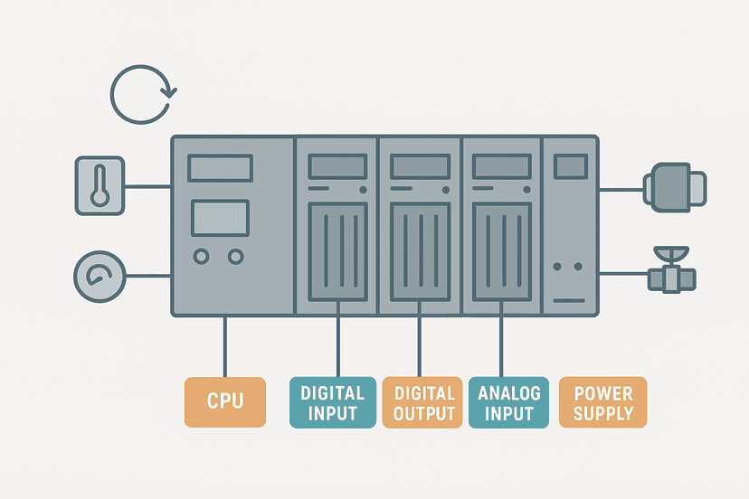
PLC programmer interview questions span five core areas: how the controller works internally (scan cycle, memory, data types), how you write logic (instructions, structure, best practices), how I/O and wiring fit together, how the PLC communicates with other systems, and how you find faults when something goes wrong. A strong candidate can move fluently between all five. The questions below are organised in that order.
Section 1: How the PLC Works
Q1. Walk me through the PLC scan cycle.
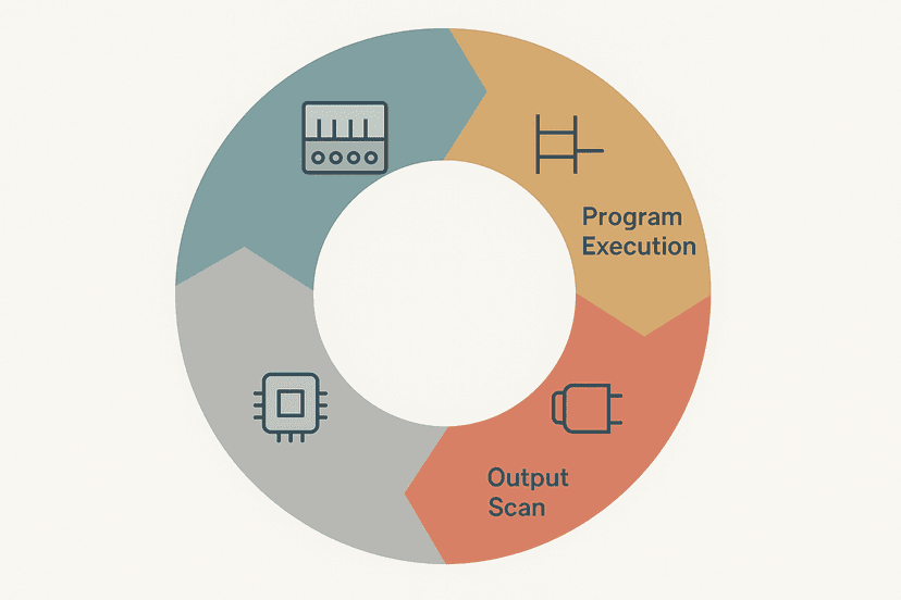
The PLC executes a continuous loop: it reads all physical inputs into an input image table, executes the program logic from top to bottom using those image values, writes the results to an output image table which then updates the physical outputs, and finally handles housekeeping tasks like communications and diagnostics. The key point interviewers listen for is 'image table'. The PLC does not read physical inputs mid-scan. If a sensor changes state after the input scan, the logic will not see it until the next cycle. For more detail on why that matters for timing-sensitive applications, see How the PLC Scan Cycle Works: Step by Step.
Q2. What affects scan time, and when does it become a problem?
Program size, number of I/O points, communication load and the use of complex math or string instructions all increase scan time. It becomes a problem when the scan is slow relative to the event you need to detect. A 20 ms scan will reliably miss a 5 ms pulse from a high-speed encoder. The answer is hardware interrupts or high-speed counter modules, not faster typing. Expect a follow-up about PLC scan cycle timing faults.
Q3. What is the difference between volatile and non-volatile PLC memory?
Volatile memory like RAM loses its contents when power is removed. Non-volatile memory such as flash or EEPROM retains data through a power cycle. Program storage is nearly always non-volatile. Data memory can be either: a retain or persistent attribute makes a variable survive power loss, which matters for accumulators, recipe values and runtime counters. Failing to mark a recipe setpoint as retentive is a classic commissioning mistake. The PLC memory and addressing post goes deeper on how vendors handle this differently.
Q4. What data types do you use regularly, and what are the gotchas?
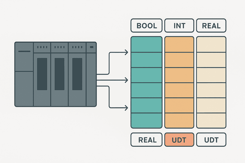
BOOL, INT, DINT, REAL and STRING cover 90 percent of everyday work. The gotchas: comparing a REAL to an exact value with an EQU instruction almost never works because floating-point rounding means 100.0 stored after a calculation is rarely exactly 100.0. Use a deadband compare instead. Also watch integer overflow: a SINT tops out at 127, and wrapping silently is a fault that takes hours to find. The PLC data types interview post covers the full range including BCD and structured types.
Section 2: Writing Logic
Q5. When would you use OTL/OTU instead of OTE?
Use a latch pair (OTL/OTU) when the condition that sets the bit and the condition that clears it are different, or when you need the state to survive a rung going false momentarily. A motor run command that should stay on after the start button is released is the classic case. OTE is fine when the output should track its rung directly, like a pilot light that mirrors a running state. The detailed breakdown is at OTL and OTU Latch Coils in Ladder Logic Explained.
Q6. What is a seal-in circuit and how does it work?
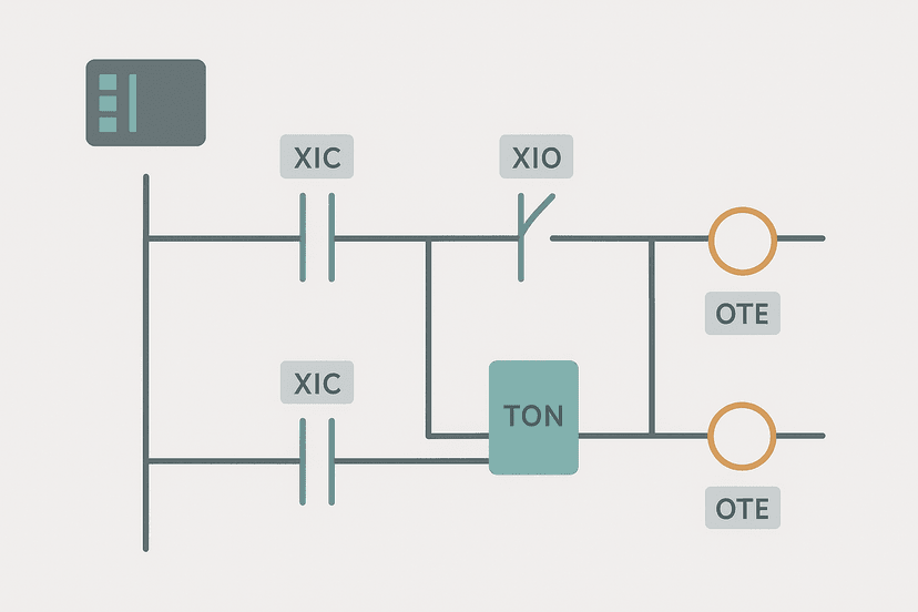
A seal-in (or hold-in) circuit places a normally-open contact from the output coil in parallel with the start contact. Once the output energises, its own contact keeps the rung true even after the momentary start signal drops. A normally-closed stop contact placed in series breaks the circuit. This is the foundation of motor start-stop control. You can try this exact circuit in the start-stop interactive ladder editor to verify it works before your interview.
Q7. Explain the difference between XIC and XIO contacts.
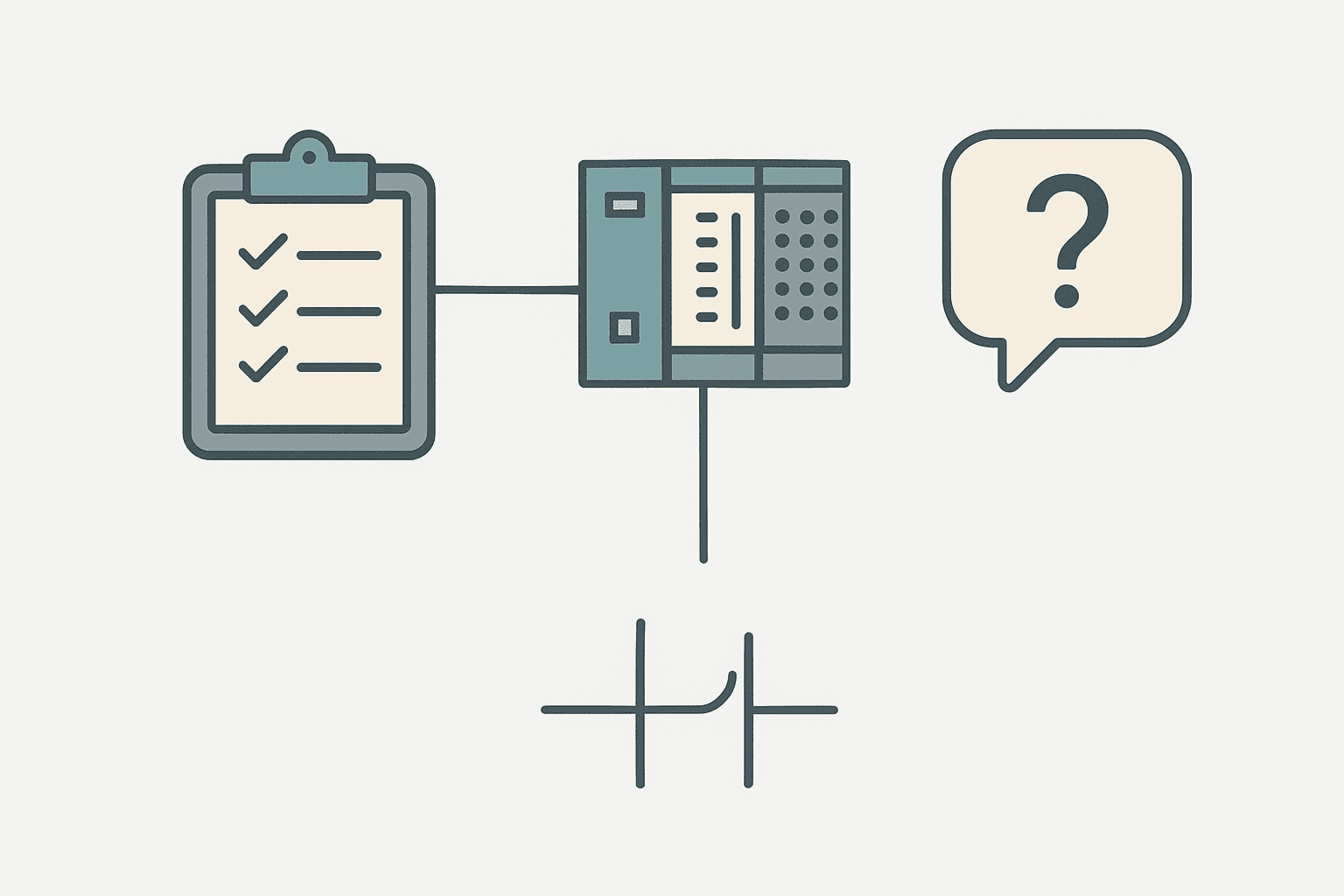
XIC (Examine If Closed) passes power when the referenced bit is 1. XIO (Examine If Open) passes power when the referenced bit is 0. The trap interviewers set here: they ask 'what does an XIO contact do when the physical input is open?' The answer depends on whether the wiring is normally open or normally closed. XIC and XIO refer to the bit state in the image table, not the physical contact position. For the full treatment see XIC vs XIO: Ladder Logic Contacts Explained.
Q8. How do TON, TOF and TONR differ?
TON starts timing when the rung goes true and resets when the rung goes false. TOF starts timing when the rung goes false and is used for run-on delays like a cooling fan that keeps running after a motor stops. TONR accumulates time whenever the rung is true and holds the count when the rung goes false, only resetting on an explicit RES instruction. A maintenance runtime tracker is the textbook TONR use case. The full comparison is at TON, TOF and TONR Timers: What Actually Differs.
Q9. What is a one-shot and why do you need it?
An OSR (one-shot rising) fires its output bit true for exactly one scan when its input rung transitions from false to true. Without it, a CTU counter would increment every scan for as long as the input stays true, which on a 10 ms scan means 100 counts per second from a single button press. Every event-driven action, counting, latching, triggering a move, needs a one-shot unless the physical signal is already a short pulse shorter than one scan. See One-Shot Rising Edge in Ladder Logic: OSR Explained for the storage bit detail that trips people up.
Q10. How do you structure a program to make it maintainable?
Use descriptive tag names that include the area, device type and function (for example, Conv1_MotorRun rather than B3:0/5). Split logic into routines or function blocks by machine section or function. Keep rungs short: one action per rung where possible. Comment every non-obvious rung. Avoid bit-of-word addressing in modern systems; symbolic tags are far easier to follow. Interviewers who ask this question are checking whether you have ever had to maintain someone else's undocumented program at midnight. Most experienced engineers have.
Q11. What is indirect addressing and when is it useful?
Indirect addressing uses a variable as a pointer to the memory location you want to read or write. Instead of writing twenty rungs to handle twenty recipe slots, you write one rung and index into an array with a counter or step variable. It is powerful for sequencers, recipe management and batch reporting. The risks: an out-of-range index can corrupt adjacent memory or generate a fault, so bounds checking is essential. The PLC addressing modes post covers direct, indirect and symbolic addressing with concrete examples.
Section 3: I/O, Wiring and Sensors
Q12. What is the difference between sinking and sourcing I/O?
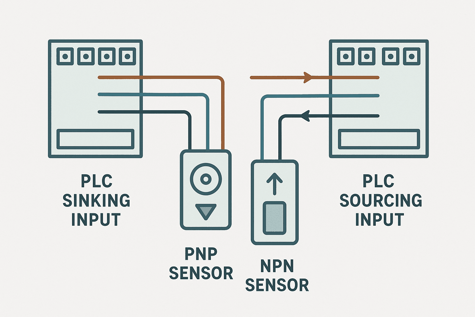
A sinking input draws current out of the field device toward the PLC common terminal. A sourcing input supplies current from the PLC to the field device. The mismatch between sensor output type (PNP or NPN) and PLC input type causes the most common wiring fault on new installations. The full wiring guide is at Sinking vs Sourcing PLC I/O: Wiring It Right.
Q13. A 4-20 mA sensor reads correctly at 4 mA but drifts at 20 mA. What do you check?
First check the loop supply voltage. At high current (20 mA) the voltage drop across the loop resistance increases, and if the supply is marginal the transmitter cannot source enough voltage to maintain the signal. Next check shield grounding: a shield connected at both ends can carry loop current that adds noise. Then check the analog input module's input impedance, which should be 250 ohms or less. Finally verify the scaling registers match the module's raw count range, which varies by platform. See 4-20 mA Scaling Formula: The PLC Engineer's Guide for the math.
Q14. What types of PLC output modules exist, and when do you choose each?
Relay outputs switch AC or DC loads up to around 2 A, are electrically isolated, and survive inductive kick well but switch slowly (around 10 ms). Transistor (solid-state) outputs switch DC only, are fast (sub-millisecond), suit high-frequency applications like stepper pulses, but have no galvanic isolation and are more vulnerable to inductive loads without protection diodes. Triac outputs handle AC loads without moving contacts but generate more heat. The full comparison with wiring examples is at PLC Output Wiring: Relay, Transistor and Triac.
Q15. How do you wire a 3-wire PNP proximity sensor to a PLC input?
The brown wire goes to 24 VDC positive, the blue wire goes to 0 V common, and the black (signal) wire goes to the PLC input terminal. The PLC input must be a sinking type (or a configurable input set to sinking mode) because the PNP sensor sources current out of the black wire. Connecting a PNP sensor to a sourcing input puts two current sources in parallel and nothing will work correctly. The wiring detail with diagrams is at 3-Wire Sensor Wiring: PNP vs NPN to PLC Inputs.
Section 4: Communications and Integration
Q16. Explain Modbus RTU in one minute.
Modbus RTU is a serial master-slave protocol where one master polls one or more slaves sequentially over RS-485. Each message contains a slave address, function code (03 to read holding registers, 06 to write a single register, 16 to write multiple), the register address, data, and a CRC. Slaves only respond when addressed. There is no spontaneous messaging. Typical settings are 9600 or 19200 baud, 8 data bits, no parity, 1 stop bit. The full frame structure and timing detail is at Modbus RTU Protocol Explained: Frames, Timing and Wiring.
Q17. What is the difference between PROFINET and EtherNet/IP?
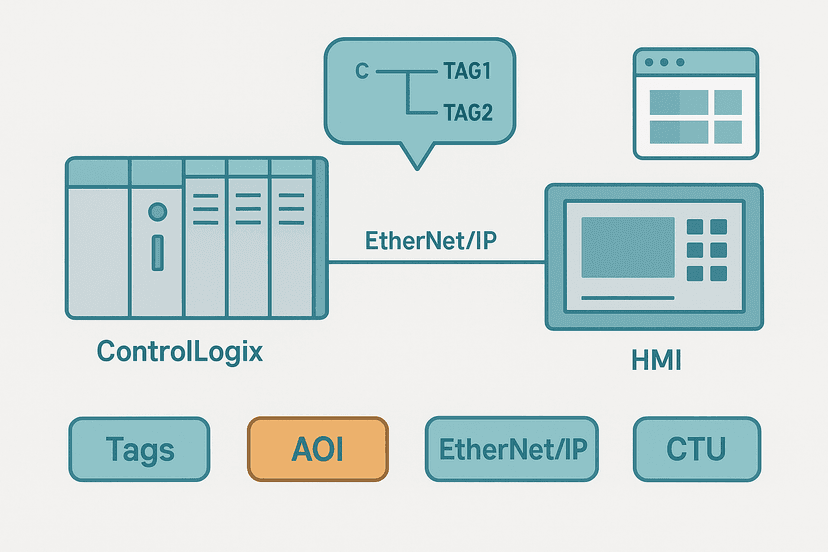
Both run on standard Ethernet hardware but use different application-layer protocols. PROFINET uses a controller-device model where the controller holds the configuration and the device responds. EtherNet/IP uses a scanner-adapter (producer-consumer) model where cyclic data is exchanged via implicit messaging and explicit messaging handles configuration and reads. PROFINET is dominant in Siemens ecosystems; EtherNet/IP is dominant in Rockwell. The EtherNet/IP Scanner vs Adapter post and PROFINET IO: Controller, Device and AR Explained cover each in detail.
Q18. What is OPC UA and why do interviewers ask about it now?
OPC UA is a platform-independent, service-oriented protocol designed for secure, reliable data exchange between PLCs, SCADA systems, MES and cloud platforms. Unlike older OPC DA which was Windows-only and COM-based, OPC UA runs on Linux, embedded systems and any operating system. Interviewers ask about it because Industry 4.0 and IIoT integration have made it a standard expectation for senior roles. The OPC UA Protocol Explained for PLC Engineers post covers the address space and security model.
Section 5: Fault Finding and Troubleshooting
Q19. A digital output is commanded on in the PLC but the field device is not responding. Walk me through your process.
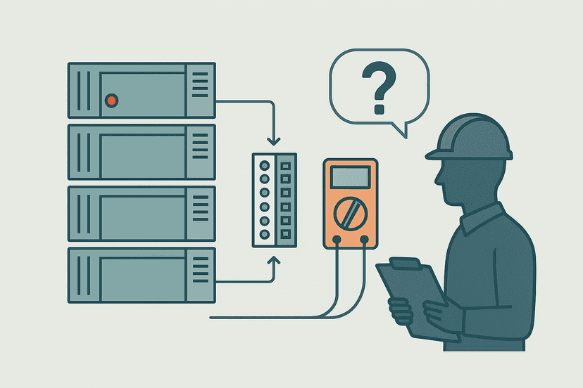
Start at the PLC: confirm in online monitoring that the output bit is actually 1. If yes, check the output module LED. If the LED is on, move to the terminal: measure voltage with a meter between the output terminal and common. If voltage is present, the fault is in the field wiring or the device itself. If voltage is absent with the LED on, suspect a blown fuse on the output common or a failed output transistor. If the LED is off but the bit is 1, the module may be in fault mode. The systematic approach is covered in PLC Output Faults: How to Diagnose Them Fast.
Q20. What does it mean when a PLC goes into a major fault and how do you recover it?
A major fault halts program execution and typically lights a solid red fault LED on the CPU. Common causes: a watchdog timeout (the scan took longer than the configured limit), an I/O communication error with a remote rack, a divide-by-zero or an array index out of bounds. Recovery steps: read the fault code from the controller diagnostics or the programming software, address the root cause, then clear the fault and attempt a restart. Never clear and restart without reading the code. The PLC CPU Faults: How to Diagnose Them post has a full fault code table.
Q21. How do you use online monitoring during troubleshooting?
Go online with the programming software and watch the live rung states. Green (or highlighted) contacts show which bits are true, which instantly narrows down whether a condition is failing in hardware or logic. Force tables let you force inputs or outputs to a known state to isolate whether a problem is in the field or in the code. Trend or data logging lets you capture intermittent faults that disappear before you can react. One thing I always do first: confirm you are actually connected to the right controller and the right task. More than once I have been staring at a program that is not the one running. See PLC Troubleshooting with Online Monitoring for the full workflow.
Q22. A sensor intermittently drops out for one scan. How do you handle it in software?
Add a TON debounce timer on the input. The output of the timer only goes true after the input has been continuously on for the debounce period, filtering single-scan glitches. For a proximity sensor, 8 to 20 ms is typical. For a level sensor on a turbulent surface, 200 to 500 ms is more appropriate. The software fix does not replace finding the root cause: check the sensor gap, cable routing near noise sources, and connector integrity. Intermittent Sensor Faults: How to Find Them covers the hardware investigation side.
Quick-Fire Questions: What Interviewers Slip in at the End
| Question | Solid answer |
|---|---|
| What is a watchdog timer? | A hardware timer that resets every scan. If the scan does not reset it in time, the CPU declares a fault and halts. It prevents a runaway program from leaving outputs in a dangerous state. |
| What is the difference between CTU and CTD? | CTU counts up from zero toward a preset. CTD counts down from a preset toward zero. Both set a DN bit when the accumulator equals the preset. See CTU vs CTD post for the edge cases. |
| Name two IEC 61131-3 languages besides ladder. | Structured Text (ST) and Function Block Diagram (FBD). Also valid: Instruction List (IL, now deprecated in the standard) and Sequential Function Chart (SFC). |
| What is a function block? | A reusable code unit with inputs, outputs and internal state that persists between calls. Unlike a function, a function block can remember values across scans, which makes it suitable for timers, counters and PID controllers. |
| What is a PFH in safety terms? | Probability of dangerous Failure per Hour. It quantifies how often a safety function is expected to fail dangerously in a given time period. IEC 62061 uses PFHd to assign SIL levels. |
Q27. What is the difference between PLC and DCS, and when would you recommend each?
A PLC was originally designed for discrete, event-driven control: a part arrives, a valve opens, a motor starts. A DCS was designed for continuous process control: temperature, flow, pressure loops that run indefinitely. Modern PLCs handle both, but DCS platforms typically offer better built-in historian integration, redundancy options and process graphics out of the box. For a small standalone machine, a PLC is almost always the right choice. For a refinery or power plant with thousands of PID loops and mandatory redundancy, a DCS makes more economic sense. The full comparison is at PLC vs DCS: Key Differences and How to Choose.
Q28. Have you worked with structured text? When would you use it over ladder?
Structured Text is the IEC 61131-3 text language that looks like Pascal. It is superior to ladder for math-heavy routines, string manipulation, array processing and complex state machines. A scaling calculation that takes five rungs in ladder takes one clean line in ST. The trade-off: ST is harder for maintenance electricians to follow on the plant floor, where ladder logic with good comments is still more readable. A pragmatic answer is: use ladder for I/O-driven logic, use ST for data manipulation inside function blocks.
Q29. What would you check first on a PLC communication fault alarm?
Check the physical layer first: cable, connectors, switch port link LED. Then check the IP address or node address configuration for duplicates. Then look at the controller's diagnostics for a specific error code. Most EtherNet/IP and PROFINET faults give you enough information in the fault log to pinpoint whether it is a network issue, a device power issue or a configuration mismatch. The PLC Communication Faults: How to Diagnose Them post has a step-by-step checklist.
Q30. What questions should you ask the interviewer at the end?
Ask what platforms and software versions the team uses. Ask about the typical size of programs in terms of I/O count and number of tasks. Ask whether there is a simulation environment or test rig available before deploying to live machines. Ask how modifications are handled: change management, version control, backup procedures. These questions signal that you think like someone who will own the system long-term, not just someone who can write a rung.
Keep Learning
These questions cover the programmer interview. If you are interviewing for a technician or troubleshooting-focused role, work through PLC Troubleshooting Interview Questions: Real Answers next. For ladder-logic-specific questions on contacts, coils and rungs, Ladder Logic Interview Questions: Real Answers fills that gap. And if you want to practice the circuits you just read about, the interactive ladder logic exercises let you toggle real inputs and watch rungs evaluate in your browser, no hardware required.
Frequently asked questions
What is the PLC scan cycle and why does it matter in interviews?
What is the difference between a retentive and a non-retentive timer?
What is the difference between OTL and OTE coils in ladder logic?
How does sinking and sourcing affect PLC input wiring?
What causes a PLC to go into fault mode?
What is the difference between global and local variables in IEC 61131-3?
What is an indirect addressing mode and when would you use it?
What is the purpose of a one-shot (OSR) instruction in ladder logic?
What communication protocols should a PLC programmer know for interviews?
How do you handle a sensor that chatters or bounces in a PLC program?
Now build it
You have just read about XIO and XIC and OTE. Reading a rung and making one behave are different skills, and the second one is the job.
Start / Stop Circuit
Beginnerabout 10 minThe first circuit every controls engineer learns: a motor that starts on a button press, keeps running when the button is released, and stops on a stop button, with stop always winning.
Build this rungFree, no signup, runs in your browser. See all 16 exercises.
Was this helpful?