PLC Data Types: Interview Questions Answered
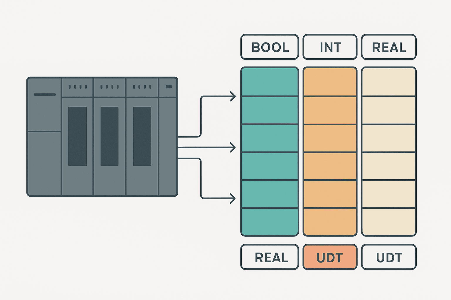
Data types questions catch more PLC candidates off guard than almost any other topic. Most people can describe a TON timer or draw a seal-in circuit, but ask them why a REAL is dangerous inside a counter rung, or what actually happens when you assign a DINT to an INT, and the room goes quiet. This post works through the 15 questions hiring engineers actually ask, with the kind of direct answers you would give if you had spent years staring at these problems on a live machine.
What Are PLC Data Types?
PLC data types are the classifications that define how many bits a variable occupies in memory, what range of values it can hold, and how the CPU interprets those bits during execution. IEC 61131-3 standardises the core set: BOOL, BYTE, WORD, DWORD, SINT, INT, DINT, LINT, USINT, UINT, UDINT, ULINT, REAL, LREAL, TIME, DATE, STRING and structured types. Every PLC platform supports a subset of these, sometimes with vendor-specific names, and choosing the wrong type is a reliable source of hard-to-find bugs.
The Core Numeric Types: BOOL, INT, DINT and REAL
These four cover the vast majority of what you will use day to day. Understanding their sizes and limits cold is the foundation of every other data-type question.
| Type | Bits | Signed? | Range | Typical use |
|---|---|---|---|---|
| BOOL | 1 | No | 0 or 1 | Discrete I/O, flags, coils |
| INT | 16 | Yes | -32768 to 32767 | Small counters, short integers |
| DINT | 32 | Yes | -2,147,483,648 to 2,147,483,647 | Large counters, encoder positions |
| REAL | 32 | Yes (IEEE 754) | ±1.2E-38 to ±3.4E+38 | Scaled analogs, PID, flow totals |
| LREAL | 64 | Yes (IEEE 754) | ±2.2E-308 to ±1.8E+308 | High-precision calculations |
A question that comes up constantly: when does INT overflow? At 32767. If your CTU counter has a DINT accumulator but your recipe target is stored as an INT, and someone types in 33000 on the HMI, the INT silently wraps to a negative number. That is not a theoretical edge case. I have seen it kill a batch count on a packaging line because the original programmer chose INT to save memory on a machine from 2003 and nobody revisited it. Read more about how PLC memory and addressing works at the bit and word level.
Interview Question: Why Is REAL Not Safe for Equality Comparisons?
This one separates candidates who have actually written PLC math from those who have only read about it. REAL is a 32-bit IEEE 754 floating-point number. The binary representation cannot store every decimal value exactly, so 0.1 + 0.2 does not equal 0.3 precisely in floating-point arithmetic. If you write IF TankLevel = 100.0 THEN you may never hit that exact bit pattern. The correct approach is to compare within a tolerance band: IF ABS(TankLevel - 100.0) < 0.05 THEN. This matters any time you use REAL in a sequencer step transition.
= or <> to compare two REAL values in PLC logic. Use a deadband or tolerance check instead. This is one of the most common bugs on analog-driven sequence steps.Interview Question: What Is a UDT and Why Would You Use One?
A User-Defined Type (UDT), called a Struct in CODESYS and some Siemens contexts, is a template that groups variables of different types under one name. Think of it as a record in a database. A typical motor UDT might contain Run_Cmd: BOOL, Run_FB: BOOL, Fault: BOOL, Speed_Setpoint: REAL, and RunHours: DINT. Once defined, you can declare Motor_1: MotorUDT and Motor_2: MotorUDT and reuse every rung that references the structure by simply changing the instance name.
On Siemens platforms this maps directly to TIA Portal Data Blocks, where you define the UDT once and instantiate it in as many DBs as you need. On Rockwell Logix the equivalent is a User-Defined Tag Type in the controller tag database. The productivity gain on a plant with 40 identical pumps is enormous and the interview answer that shows you understand it is: it enforces consistency, eliminates copy-paste errors, and makes global changes possible in one place.
Interview Question: How Do Arrays Work in a PLC?
An array is a contiguous block of identically typed elements accessed by an integer index. Declare Recipe: ARRAY[0..9] OF REAL and you get 10 REAL values at indices 0 through 9. The power comes from indirect addressing: if RecipeSelect is a DINT holding 3, then Recipe[RecipeSelect] reads element 3 at runtime without any extra rungs. This is how counter instructions feed recipe-driven batch targets and how you build compact sequencers without a wall of duplicate rungs.
One gotcha: most platforms do not check array bounds at runtime by default. If RecipeSelect holds 15 and your array is only 0..9, you will read whatever is in the memory immediately after the array. On Rockwell Logix, out-of-bounds access faults the controller. On some older platforms it silently reads garbage. Always clamp your index variable before using it.
Interview Question: WORD vs DWORD vs BYTE, What Is the Difference?
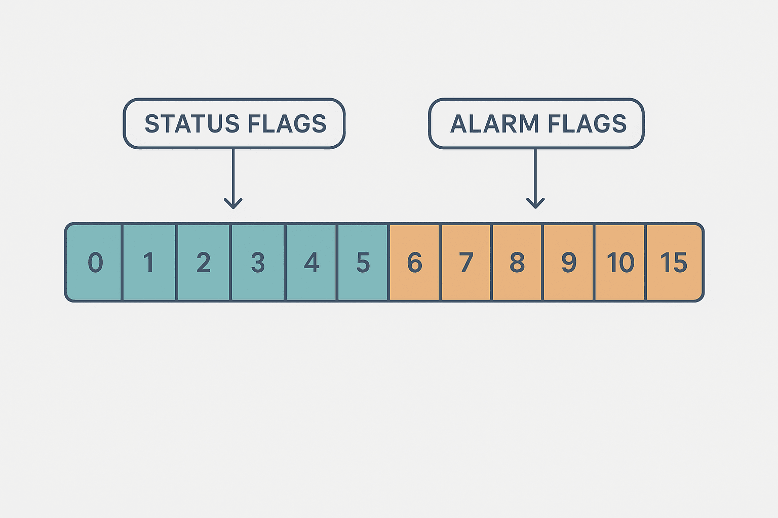
These are bit-string types, not numeric types. A BYTE is 8 bits, a WORD is 16 bits and a DWORD is 32 bits. They hold the same number of bits as USINT, UINT and UDINT respectively, but the intent is different: bit-string types are for bitwise operations (AND, OR, XOR, shift) rather than arithmetic. You would use a WORD to pack eight alarm flags for transmission over Modbus RTU in a single register, then unpack them on the receiving end with bit-masking.
Interview Question: What Is the TIME Data Type?
TIME is a 32-bit signed integer internally, but it represents duration in milliseconds and is written in IEC 61131-3 notation as T#3s, T#500ms or T#1m30s. It is the type you use for timer presets in TON, TOF and TONR instructions. A common mistake is assigning a plain DINT (holding, say, 3000) directly to a timer preset. On some platforms that works because TIME and DINT are both 32-bit, but it is bad practice and will confuse anyone reading the code.
Interview Question: Retentive vs Non-Retentive Memory
Non-retentive variables reset to their initial value on every power cycle or program download. Retentive variables keep their last value, stored in battery-backed SRAM or capacitor-backed memory. The question is: which variables should be retentive? Run-hour totals, batch counters, recipe selections, setpoints that operators have tuned, and any latch that must survive a power blip. Everything else should be non-retentive so the machine starts in a known, safe state. Accidentally making a fault latch retentive means a fault from last week is still active when the machine powers up Monday morning, which is exactly as confusing as it sounds.
On Siemens S7, retentive behaviour is set per-variable in the data block properties. On Rockwell Logix, you mark tags as retentive in the tag properties. If you are working through a Structured Text program in TIA Portal, retentivity is handled at the DB level, not inside the code itself.
Interview Question: What Happens When You Mix Data Types in a Calculation?
IEC 61131-3 requires explicit conversion functions: INT_TO_REAL, DINT_TO_REAL, REAL_TO_INT and so on. Assigning a REAL result to an INT truncates (not rounds) the decimal. Assigning a DINT to an INT truncates the upper 16 bits. Some platforms (older Siemens S7-300 ladder) do implicit widening but not narrowing. Rockwell Studio 5000 will flag a type mismatch at compile time. The safe rule: always convert explicitly, and always ask yourself whether precision loss on the narrow end is acceptable.
Interview Question: What Is a STRING in a PLC and What Are the Limits?
STRING holds a sequence of ASCII characters. In IEC 61131-3, STRING[80] declares a string of up to 80 characters. Rockwell Logix has its own STRING type with a 82-character default (two bytes for length, 82 for data). Siemens S7 uses String[n] with a maximum of 254 characters. Strings are useful for recipe names, alarm messages and serial protocol parsing, but they are expensive in memory and slow to process. Never put string operations inside a fast scan task. One application where I had to debug a 5 ms scan task had STRING comparisons in the main OB that were adding 3 ms per scan. Moving them to a slower cyclic OB fixed it immediately.
Interview Question: How Does Addressing Differ Between Platforms?
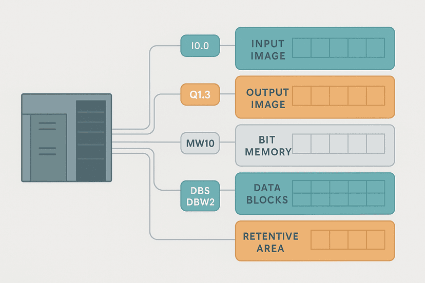
This is where vendor knowledge matters. Older Siemens S7-300/400 used absolute addressing: I0.0 for input byte 0 bit 0, MW10 for memory word 10, DB5.DBD20 for double-word at byte 20 in data block 5. Modern S7-1200/1500 in TIA Portal uses symbolic tags almost exclusively, with absolute addresses optional. Rockwell Logix dropped fixed memory addressing entirely in favour of named tags: every variable is a named tag with a type, and the CPU handles memory layout. This is a huge ergonomic improvement but it means you cannot write N7:0 on a Logix controller the way you could on an old SLC-500.
If you are working on a legacy platform, PLC memory and addressing has a detailed breakdown of file-based vs tag-based memory. Understanding both systems is expected in any mid-level or senior interview.
A Ladder Example: Indexed Recipe Selection
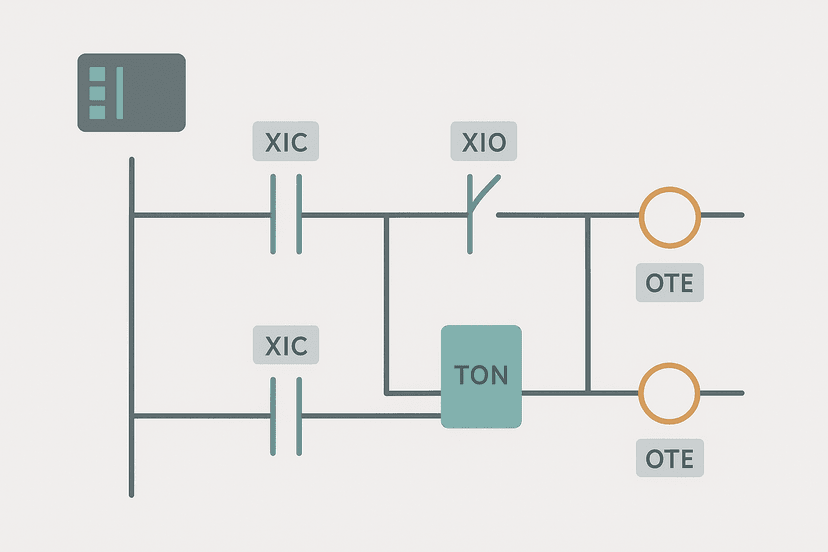
The rung below shows how an array index and a UDT work together in practice. When the operator selects a recipe number on the HMI, the MOV writes the array element into the active setpoints. This pattern eliminates duplicate rungs and is a common follow-up question after the UDT and array theory questions.
Array-Indexed Recipe Load with Range Clamp (Studio 5000 / Logix). Ladder logic (4 rungs): Rung 0: examine if HMI_LoadRecipe is on (XIC), then examine if Machine_Running is off (XIO), then latch output Recipe_Load_Latch (OTL). Rung 1: examine if Recipe_Load_Latch is on (XIC), then LIM on 0, then MOV on Recipe[HMI_RecipeSelect].FillTime_ms. Rung 2: examine if Recipe_Load_Latch is on (XIC), then LIM on 0, then MOV on Recipe[HMI_RecipeSelect].TargetWeight_kg. Rung 3: examine if Recipe_Load_Latch is on (XIC), then unlatch output Recipe_Load_Latch (OTU). Rung 1 latches a one-scan load request when the operator presses Load and the machine is idle. Rungs 2-3 use LIM to clamp the index 0-9 before reading from the REAL array elements inside the Recipe UDT, preventing out-of-bounds access. Rung 4 immediately unlatches so only one scan of data is transferred.
Interview Question: What Is the Difference Between VAR, VAR_INPUT and VAR_OUTPUT in a Function Block?
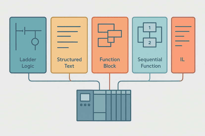
This is an IEC 61131-3 Structured Text question that comes up when interviewing for roles that involve writing reusable function blocks. VAR is an internal variable, invisible outside the block. VAR_INPUT is passed in by the caller and read-only inside the block. VAR_OUTPUT is written by the block and read by the caller. VAR_IN_OUT is passed by reference: the block can both read and write it. Getting these wrong means your function block either cannot receive its parameters or cannot return results, which is a straightforward compile error, but the interview question is really testing whether you understand encapsulation. The 5 types of PLC programming languages post covers where function blocks sit in the IEC 61131-3 picture.
Quick-Reference: Data Type Gotchas to Know Cold
- REAL equality comparisons always fail eventually. Use a tolerance band.
- INT overflows silently at 32767 on most platforms. Use DINT for anything that could grow large.
- Array indices are zero-based in IEC 61131-3 unless you declare otherwise. Off-by-one errors are common.
- TIME literals use the T# prefix. Passing a bare DINT to a timer preset is technically wrong even if the compiler allows it.
- Retentive memory survives power loss. Non-retentive resets on every power-up. Choose deliberately.
- STRING operations are slow. Keep them out of fast scan tasks.
- Explicit type conversion functions (INT_TO_REAL, REAL_TO_INT) are required in strict IEC 61131-3 implementations. Do not rely on implicit casting.
- WORD, BYTE and DWORD are for bitwise operations. UINT, USINT and UDINT are for arithmetic. They are the same bits but different intent.
What to Read Next
Data types sit at the heart of PLC programming, but interviews test the whole picture. Work through ladder logic interview questions for the logic-design side, then check PLC troubleshooting interview questions for the fault-finding questions that always come up in technical screens. If you want to go deeper on memory and addressing before your interview, PLC memory and addressing explained covers the platform-by-platform detail that rounds out the data-type picture.
Was this helpful?