Studio 5000 Interview Questions: Real Answers
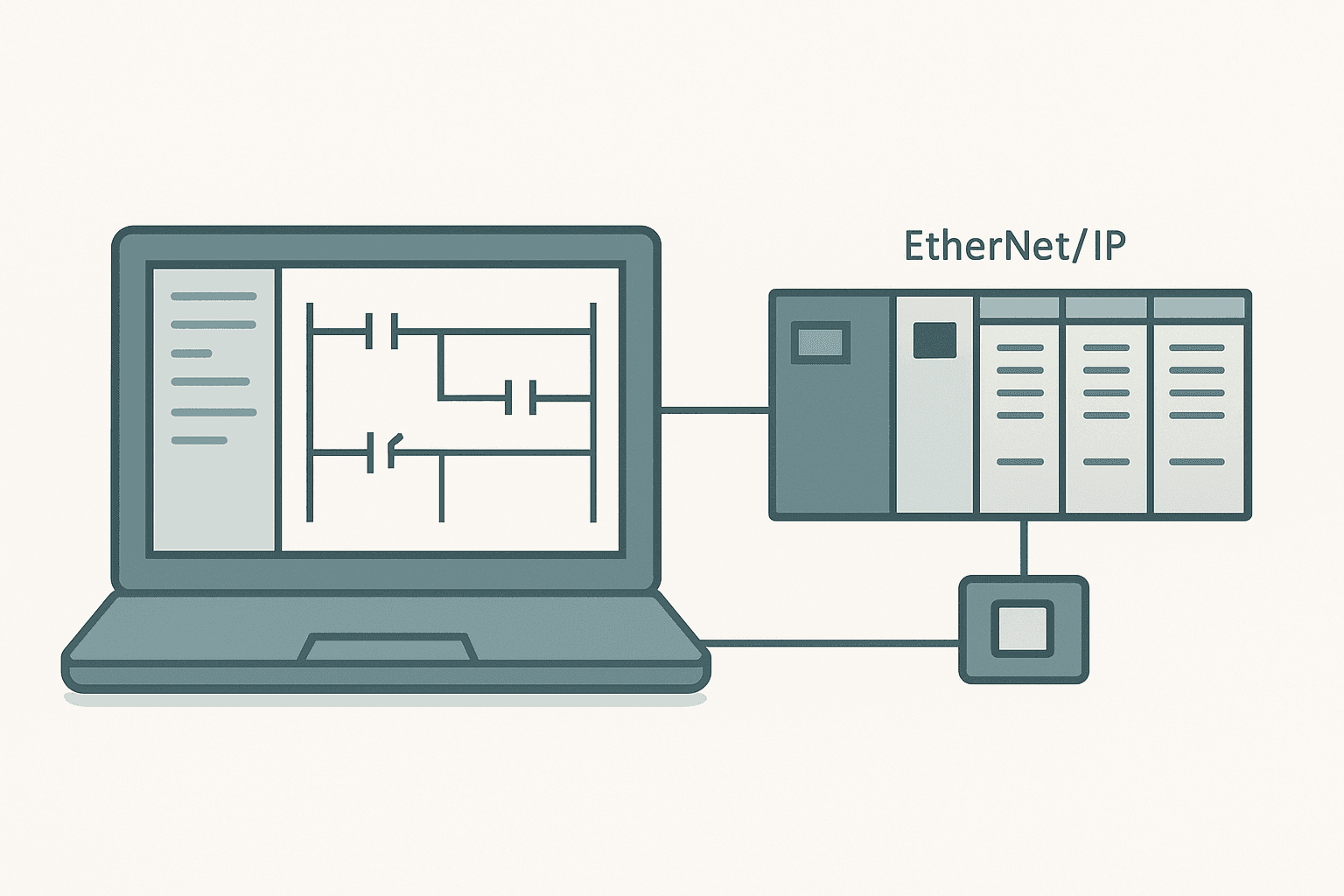
Studio 5000 Logix Designer is on more job descriptions than any other PLC software package right now. Interviewers expect you to know it beyond the basics: not just that you can open a project, but that you understand the tag database architecture, task scheduling, AOI design, and how EtherNet/IP connections actually behave. This post covers the questions that come up again and again, with the kind of specific answers that separate a candidate who has actually commissioned a ControlLogix system from one who has only read the manual.
What Is Studio 5000 Logix Designer?
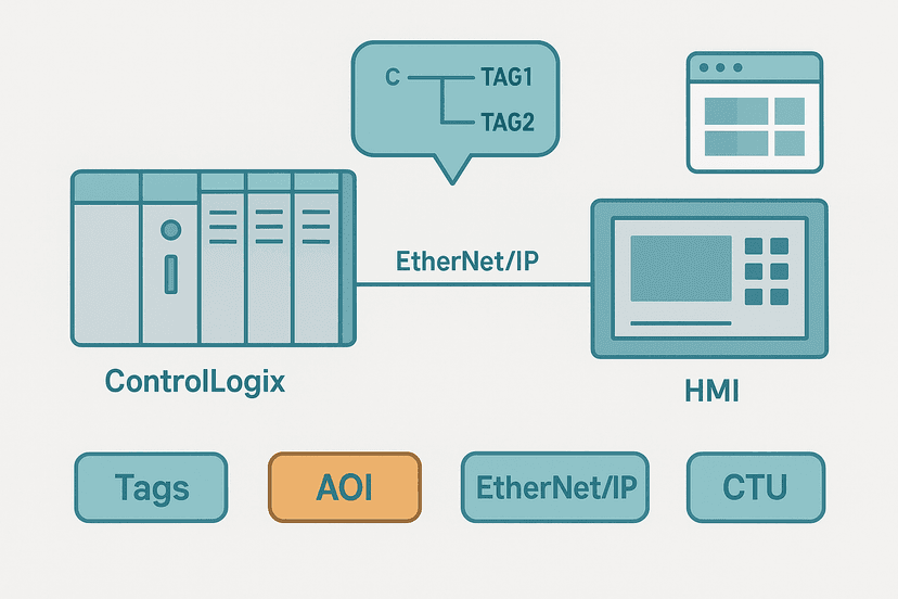
Studio 5000 Logix Designer is Rockwell Automation's programming environment for the Logix family of controllers: ControlLogix, CompactLogix, GuardLogix, and Compact GuardLogix. It replaced RSLogix 5000 starting around version 21. The platform uses a tag-based, object-oriented architecture where every piece of data is a named tag with a defined data type, and all I/O, timers, counters, and user data live in the same unified tag database. Controllers can run multiple tasks, each containing multiple programs and routines, and can connect to remote I/O over EtherNet/IP, DeviceNet, or ControlNet.
Studio 5000 Interview Questions: Tags and Data
Q1: What are the tag scopes in Studio 5000, and when do you use each?
There are two scopes: Controller scope and Program scope. Controller-scoped tags are global. Any routine in any program can read or write them, which makes them the right choice for data shared between programs, HMI tags, and inter-task communication. Program-scoped tags are local to one program and invisible outside it. Use them for internal working variables, timer and counter instances that belong to a specific machine module, and anything where you want to prevent accidental cross-program writes. On a large project, keeping tags local where possible makes the project cleaner and easier to debug. You can read more about how tag addressing works across the Logix family in PLC Addressing Modes: Direct, Indirect and Symbolic.
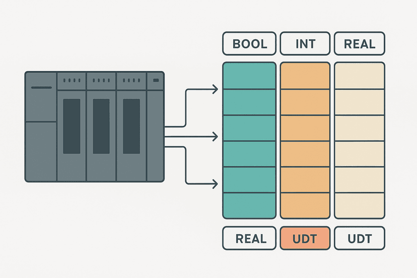
Q2: Explain the BOOL, SINT, INT, DINT, and REAL data types and give a typical use for each.
| Type | Size | Range | Typical use |
|---|---|---|---|
| BOOL | 1 bit | 0 or 1 | Digital I/O, coil outputs, flags |
| SINT | 8-bit signed | -128 to 127 | Small counters, compact arrays |
| INT | 16-bit signed | -32768 to 32767 | Word-level I/O, Modbus registers |
| DINT | 32-bit signed | +/-2.1 billion | Counters, encoder positions, large presets |
| REAL | 32-bit float | IEEE 754 | Analog scaling, PID setpoints, engineering units |
Interviewers often follow this up by asking what happens when you move a REAL into a DINT. The fractional part is truncated, not rounded. That trips people up on commissioning when a scaled analog value like 24.9 becomes 24 in a DINT. For a deep look at data types in interview context, see PLC Data Types: Interview Questions Answered.
Studio 5000 Interview Questions: Tasks and Scan Cycle
Q3: How does the ControlLogix multitasking model work?
ControlLogix runs a preemptive priority scheduler. You can have up to 32 tasks. Each task gets a priority level (1 to 15, lower number = higher priority). A higher-priority task can interrupt a lower-priority one mid-scan. The one Continuous task runs whenever no other task is executing. Periodic tasks fire on a timer (configurable from 1 ms up). Event tasks fire on specific triggers like a motion axis event or an I/O interrupt. On a conveyor system I commissioned, we ran a 5 ms Periodic task for drive control and a separate 20 ms Periodic task for HMI data updates. Separating them kept the drive loop deterministic without the HMI logic inflating scan time. Understanding scan-cycle behavior is foundational: How the PLC Scan Cycle Works: Step by Step covers this well.
Q4: What causes a Task Overlap fault, and how do you fix it?
A Task Overlap fault (type 6, code 33) occurs when a periodic or event task takes longer to execute than its configured period. So if a 10 ms Periodic task takes 12 ms to solve, it overlaps its next trigger. The fix is to profile the task in the Controller Diagnostics, find which program or routine is consuming excessive time, and either optimize the logic or increase the task period. You can also enable the Overlap checkbox in the task properties, which tells the controller to allow overlap instead of faulting, but that is only appropriate when missing a cycle is acceptable. See PLC Scan Cycle Problems: Logic and Timing Faults for practical troubleshooting steps.
Studio 5000 Interview Questions: Add-On Instructions
Q5: What is an AOI and what are its advantages over a standard subroutine?
An Add-On Instruction (AOI) is a custom instruction block with defined input, output, and InOut parameters plus local internal tags. When you call an AOI, Studio 5000 creates a backing instance tag (the AOI's data structure) that holds all its local state. Advantages over a JSR/RET subroutine call: parameters are visible right on the rung, the AOI can be source-protected so the logic is hidden from the end user, you can add it to the instruction palette so it looks like a native instruction, and changes to the AOI definition propagate to every instance. On a multi-line packaging project we standardized all conveyor zones as a single AOI. Any zone change was made once and applied to 40 instances automatically.
Q6: What is the difference between Input, Output, and InOut parameters in an AOI?
Input parameters pass data into the AOI by value. The AOI sees a copy; changes inside do not affect the caller's tag. Output parameters pass data back to the caller by value at the end of the AOI scan. InOut parameters pass a reference: the AOI reads and writes the caller's actual tag directly. Use InOut for large UDTs (User-Defined Types) where copying would be wasteful, or when the AOI needs to modify the caller's data in place, such as updating a status structure.
Studio 5000 Interview Questions: EtherNet/IP and Connectivity
Q7: Explain the difference between implicit and explicit messaging in EtherNet/IP.
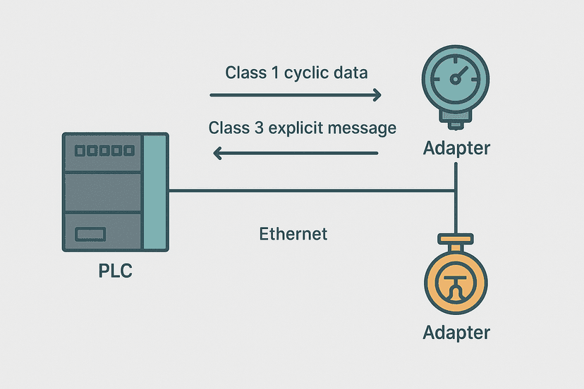
Implicit messaging (Class 1) is cyclic and connection-based. The scanner and adapter exchange I/O data automatically at the RPI rate with no ladder logic needed. This is how remote I/O modules and most drives send their process data. Explicit messaging (Class 3 or UCMM) is on-demand and triggered by a MSG instruction in ladder logic. You use it to read a VFD parameter, write a configuration value, or query a device's identity object. Explicit messages consume connection resources and have higher latency, so they are not suitable for real-time control data. For a deep look at how scanner and adapter roles split this work, see EtherNet/IP Scanner vs Adapter: How It Works.
Q8: How do you handle an EtherNet/IP communication loss safely in ladder logic?
Every remote I/O adapter module has a .ConnectionFaulted bit in its input data structure (for example, Remote_Rack:I.ConnectionFaulted). Monitor that bit in logic. When it goes true, latch a fault, command outputs to a safe state, and raise an HMI alarm. Also configure each output module's fault state and fault value in the module properties so outputs drop safe even if the scanner cannot execute logic. For a full worked example of this pattern, see EtherNet/IP Communication Loss: How to Diagnose It. And if you want to practice the fault-latch pattern itself, the Set-Reset exercise in the interactive ladder editor is a good starting point.
Studio 5000 Interview Questions: Safety and GuardLogix
Q9: What is a GuardLogix controller and how does it differ from a standard ControlLogix?
GuardLogix is a TUV-certified SIL 2 / PLd safety controller that runs inside the standard ControlLogix chassis. It has a primary CPU and a separate safety co-processor (the 1756-L7SP or integrated on newer models). The standard partition and the safety partition run independently. Safety logic lives in a separate safety task, uses safety-rated I/O modules (1791DS or 1734-IB8S for example), and can only be written or modified after entering a safety password. Standard logic cannot write safety tags directly. The architecture is described in IEC 62061 and ISO 13849-1 terms: dual-channel, cross-checked, with diagnostic coverage built into the safety I/O modules. If you need to brush up on safety integrity levels before an interview, IEC 62061 SIL Levels: What They Actually Mean is worth reading.
Q10: What is a safety signature and why does it matter?
A safety signature is a CRC-based fingerprint generated when you lock the safety task. It covers the safety program code, safety tags, and safety configuration. Any modification to the safety partition invalidates the signature. Certification bodies and end-of-line test procedures often record the safety signature. If the signature in the controller does not match the approved value, the machine cannot be released. This is a mandatory step in any GuardLogix commissioning: generate the signature, record it in the machine documentation, and verify it after any future modification.
Studio 5000 Interview Questions: Programming Patterns
Q11: How do you implement a latching alarm that requires operator acknowledgement?
The standard pattern is: detect the fault condition with an OSR (One-Shot Rising) to capture the leading edge, OTL the fault latch bit on that edge, drive the HMI alarm output from the latch bit, and OTU the latch only when the HMI acknowledgement bit is true AND the fault condition has cleared. This prevents the operator from acknowledging an alarm that is still active. The OSR instruction is covered in detail at One-Shot Rising Edge in Ladder Logic: OSR Explained.
Q12: When would you use OTL/OTU instead of OTE, and what is the risk?
OTL (latch) and OTU (unlatch) are retentive: the bit holds its state when the rung goes false. Use them for alarms, mode states, and anything that needs to stay set after the condition that set it has gone away. OTE is non-retentive: it follows the rung condition exactly. The risk with OTL/OTU is that if the OTU rung is not reached (because of a fault, a jump, or a task being disabled), the latch stays set indefinitely. Always make sure every OTL has a matching OTU somewhere in the scan. The full comparison is at OTL and OTU Latch Coils in Ladder Logic Explained.
Q13: How do XIC and XIO differ, and give a real example where using XIO is essential?
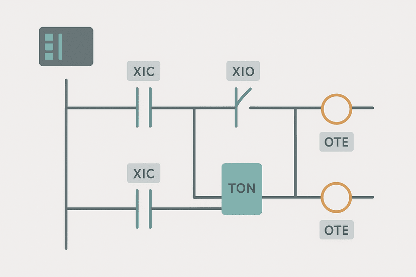
XIC (Examine if Closed) passes logic power when the referenced bit is 1. XIO (Examine if Open) passes logic power when the referenced bit is 0. XIO is essential for interlocks. A classic example: a guard door switch wired to a PLC input. If the door is open the input is 0. You wire the interlock as XIO(Door_Open) in series with the machine run rung. If the door opens, Door_Open goes 1, XIO fails, and the machine stops. You cannot achieve that with XIC alone. See XIC vs XIO: Ladder Logic Contacts Explained for more depth on this.
Q14: What is indirect addressing in Studio 5000, and give a use case?
Indirect addressing lets you use a tag's value as the index into an array at runtime. In Studio 5000 you write it as MyArray[IndexTag] where IndexTag is a DINT. A practical use case: a recipe system where RecipeStep is a DINT that increments through a sequence. Each step reads its setpoint from RecipePresets[RecipeStep] instead of having 20 separate rungs with hard-coded values. This keeps logic compact and makes adding recipe steps a data change rather than a code change. The broader addressing model is covered in PLC Addressing Modes: Direct, Indirect and Symbolic.
Q15: How do you read a 4-20 mA analog input in Studio 5000 and scale it to engineering units?
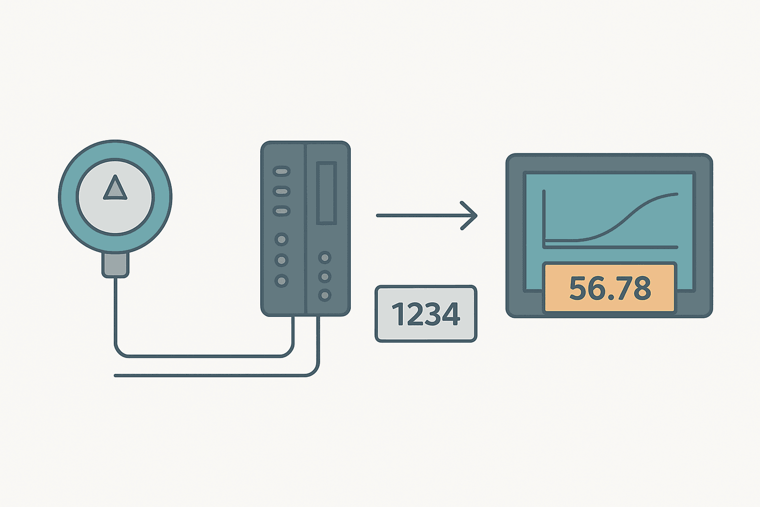
A 1756-IF16 or similar analog input module converts the 4-20 mA signal to a raw integer, typically 0 to 32767 for a 0-20 mA range or 6554 to 32767 for a 4-20 mA range, depending on module configuration. You then apply a linear scaling formula to convert raw counts to engineering units. In Studio 5000 ladder you can use the SCL (Scale) instruction or do the math with CPT (Compute). The formula is: EU = (Raw - Raw_Min) / (Raw_Max - Raw_Min) * (EU_Max - EU_Min) + EU_Min. For the full worked formula and code, see 4-20 mA Scaling Formula: The PLC Engineer's Guide. The wiring side is covered at PLC Analog Input Wiring: 4-20 mA Step by Step.
A Few Tips Before the Interview
Studio 5000 interviews almost always include a practical component. You might be asked to open a project, trace a fault, or write a small routine live. A few things that consistently trip people up in technical screens:
- Know the difference between a ControlLogix and a CompactLogix chassis. ControlLogix uses separate modules in a 1756 chassis. CompactLogix (1769 or 5069) integrates the PSU and CPU.
- Be ready to explain why a major fault halts the controller and how a fault routine can recover from it.
- Know that produced/consumed tags require a specific connection license and that the producer must be configured first.
- Understand that the MSG instruction requires a connection (either a dedicated connection or UCMM) and that connection limits are finite.
- Be able to describe the difference between the Logix program routines: Main Routine, Fault Routine, and Power-Up Handler, and when each executes.
If you want to verify your troubleshooting instincts before the interview, PLC Troubleshooting with Online Monitoring walks through the online tools you would use in exactly this kind of scenario. And if the role has a safety component, make sure you can talk to ISO 13849-1 PL Levels in addition to the GuardLogix specifics above.
Keep Learning
If this post covered the Studio 5000-specific material, the next step is to make sure your general Allen-Bradley knowledge is just as solid. Allen-Bradley PLC Interview Questions: Real Answers covers the platform-level questions that often come before the software-specific ones. For ladder logic pattern questions that appear in almost every PLC interview regardless of vendor, Ladder Logic Interview Questions: Real Answers is the companion piece. And if you want to test your hands-on ladder skills before a practical interview exercise, try building and toggling circuits in the free interactive ladder sandbox.
Frequently asked questions
What is the difference between a base tag and an alias tag in Studio 5000?
What does an Add-On Instruction (AOI) do in Studio 5000?
How many tasks can a ControlLogix controller run, and what types are available?
What happens to outputs during a major fault in a ControlLogix controller?
What is the role of the EtherNet/IP scanner in a ControlLogix system?
How does produced and consumed tag communication work in Studio 5000?
What is the difference between a ControlLogix and a CompactLogix controller?
How do you prevent a Program Fault from halting an entire ControlLogix project?
What is the RPI setting in a Studio 5000 EtherNet/IP connection, and how do you choose it?
Now build it
You have just read about OTU and XIO and OTL. Reading a rung and making one behave are different skills, and the second one is the job.
State Coil / Fault Coil
Intermediateabout 15 minA fault lamp that latches ON when any alarm condition occurs, even briefly, and only clears on Reset. And if the condition is still present when Reset is released, the fault comes right back.
Build this rungFree, no signup, runs in your browser. See all 16 exercises.
Was this helpful?