PLC Analog Output Wiring: 4-20 mA and 0-10 V
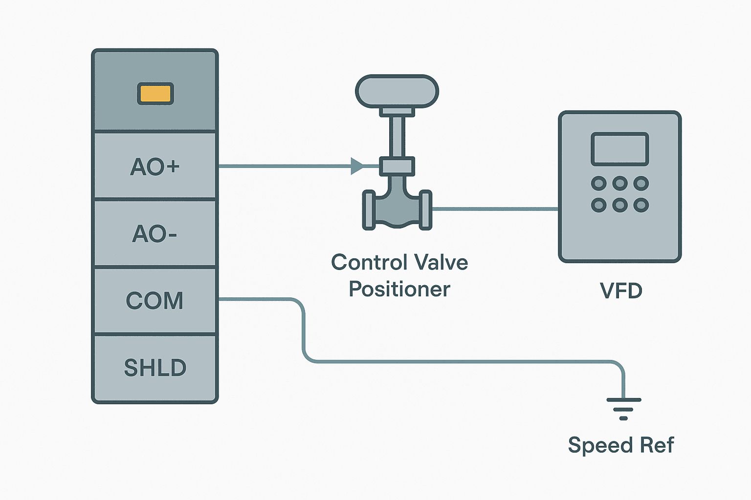
Analog output wiring trips up engineers far more often than analog inputs. The input side is mostly passive: signal comes in, you read it. The output side has you sourcing current or voltage into a load you may not fully know, through a cable that runs past noisy power wiring, into a device that may expect a specific impedance. Get any one of those things wrong and your valve barely moves, your VFD ignores the speed reference, or your output channel quietly burns out. This guide covers PLC analog output wiring for both 4-20 mA current loops and 0-10 V voltage signals from the terminal screw to the field device.
What Is PLC Analog Output Wiring?
PLC analog output wiring is the process of connecting a PLC analog output module to a field device, such as a control valve positioner, VFD speed reference input, or proportional solenoid, so that the PLC can command a continuously variable signal. The module converts a digital value from the PLC program into either a 4-20 mA current or a 0-10 V (or 0-5 V, 1-5 V, or plus or minus 10 V) voltage, and the field device responds proportionally. Correct wiring ensures signal integrity, accurate control and protection of the module.
4-20 mA vs 0-10 V: Choosing the Right Signal Type
The choice between current and voltage is usually made for you by the field device, but it helps to understand why one is better in a given situation.
| Property | 4-20 mA Current | 0-10 V Voltage |
|---|---|---|
| Noise immunity | High (current is constant regardless of cable resistance) | Lower (voltage divides across impedances) |
| Max cable run | Typically 300 m or more at low loop resistance | Practical limit around 10-30 m before loading matters |
| Wire-break detection | Yes: 0 mA or below 4 mA signals a fault | No: 0 V is valid and also a broken wire |
| Load requirement | Max loop resistance limited by compliance voltage | Minimum load impedance typically 10 kilohms |
| Typical applications | Control valves, positioners, long cable runs | VFD speed reference, short panel runs, servo setpoints |
If the cable run is longer than about 15 metres or passes through a noisy environment, use 4-20 mA every time. The current-loop signal is immune to resistive voltage drop in the cable, which is why it has dominated process instrumentation for decades. For short intra-panel runs to a VFD speed reference, 0-10 V is fine and saves you the compliance-voltage headache.
Understanding Compliance Voltage and Load Limits
This is the number one thing people skip in the datasheet. Every 4-20 mA analog output module has a compliance voltage, typically 12 to 28 VDC, which is the maximum voltage the module can push across the loop to maintain the current. Your total loop resistance must stay below:
Max load (ohms) = Compliance voltage / 0.020 A
So a module with 12 V compliance can handle at most 600 ohms. Add up cable resistance (roughly 0.034 ohms per metre per conductor for 0.75 mm2 wire, times two for the return), any series fuse resistance, and the field device input impedance. A 250-ohm receiver, 100 metres of 0.75 mm2 cable (about 6.8 ohms round trip) and a small inline fuse adds up to roughly 260 ohms, which is fine at 12 V. But add a second receiver in series and you are at 510 ohms, and you are close to the edge before cable resistance makes it worse.
Sourcing vs Externally Powered Output Channels
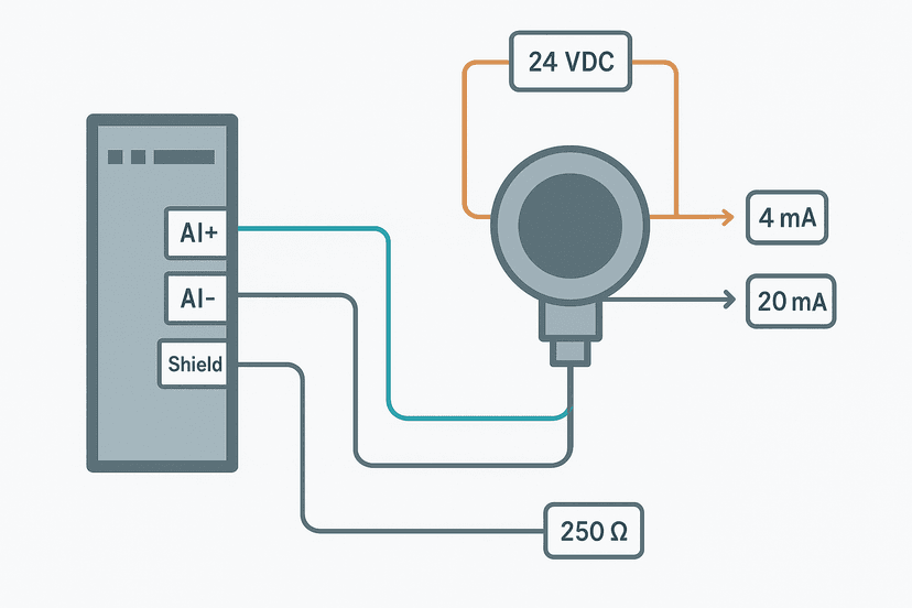
Analog output modules come in two flavours: sourcing (also called active or internally powered) and passive (externally powered). A sourcing module provides its own loop power from an internal DC rail. You connect AO+ and AO- (or COM) and you are done. A passive module's channel is not energised internally: you must supply loop power from an external 24 VDC source in series with the loop.
Most modern PLC analog output modules, including the Siemens SM 1232, Rockwell 1769-OF4 and Mitsubishi FX5-4DA, are sourcing types. But rack-based systems with isolated channel modules sometimes require an external supply. Check the module's terminal assignment diagram in the datasheet. If you see a separate PWR or EXT+ terminal, the channel is externally powered. Connecting a sourcing module to an externally powered loop without understanding the circuit creates two voltage sources fighting each other, which will at minimum cause measurement errors and can damage the module.
Step-by-Step Wiring: 4-20 mA Current Loop
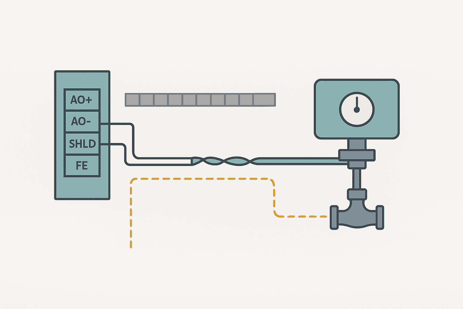
- Calculate total loop resistance before you run any cable. Include cable resistance, receiver impedance and any series components.
- Select the correct wire gauge. For runs under 50 m, 0.75 mm2 (18 AWG) is usually fine. Over 100 m, move to 1.5 mm2 (16 AWG) to keep resistance low.
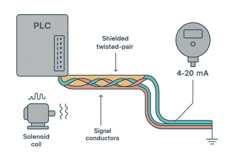
- Use shielded twisted pair (STP) cable rated for instrumentation use. The twist keeps the differential signal balanced. The shield blocks capacitively coupled noise.
- At the module, terminate AO+ to the positive output terminal and AO- (or COM) to the return terminal. On a sourcing module this is all you need.
- Route the cable in a dedicated instrument cable tray, physically separated from 230 VAC or motor power cables. If cross-routing is unavoidable, cross at 90 degrees. See Control Panel Wire Routing and Segregation for the full rules.
- At the field device, connect the signal wires to the input terminals as marked on the device (usually AI+/AI- or IN+/IN-).
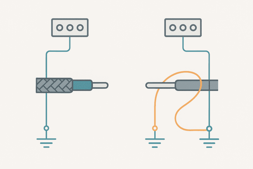
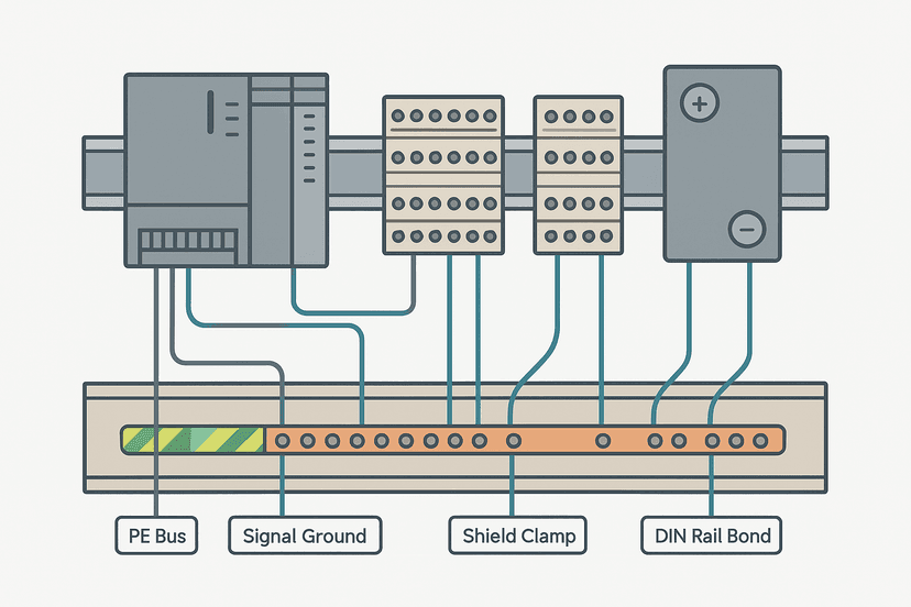
- Ground the shield at the panel end to the instrument ground bus or a dedicated shield bus bar. Leave the field-device end of the shield floating (disconnected). This single-point grounding is explained in detail in Cable Shield Grounding: One End or Both?.
- Connect the cable shield drain wire and the module's functional earth (FE) terminal to the instrument ground bus, not to the noisy DC common of the 24 VDC power supply.
- Verify the module channel is configured for 4-20 mA in both hardware (jumper or DIP switch if present) and in the PLC software configuration.
Step-by-Step Wiring: 0-10 V Voltage Output
- Confirm the receiving device's input impedance. It must be at least 10 kilohms, and preferably 20 kilohms or higher, to avoid loading the output. A VFD analog input is typically 10 to 20 kilohms, which is fine.
- Keep the cable run short: under 10 metres for most installations, 30 metres maximum in a very low-noise environment.
- Use shielded twisted pair. Even for short runs inside a panel, the shield matters if the cable passes near VFD output cables or contactor wiring.
- At the module, connect AO+ to the positive voltage output terminal and AO- or COM to the signal common terminal.
- At the VFD or other device, connect to the analog input terminals exactly as specified in the drive manual. Many drives have a dedicated analog input common that must be connected; do not assume the drive's DC common and analog common are the same terminal. VFD Parameters Explained covers this for common drive families.
- Ground the shield at the panel end only, same rule as current loops.
- Do not share the AO- or COM terminal between a voltage output channel and a current output channel unless the module datasheet explicitly permits it. Many modules have isolated channels for exactly this reason.
- Set the module channel to voltage mode in hardware and software.
Software Configuration: Matching the Module to the Wire
Hardware wiring is only half the job. If the software configuration does not match, the output either does nothing or outputs the wrong signal type. On a Siemens S7-1200, you configure each SM 1232 channel in TIA Portal under the device properties: select current or voltage, set the output range, and enable or disable the short-circuit monitoring. On a Rockwell 1769-OF4 in Studio 5000, you set the output type and range per channel in the module properties under the General tab, and you need to match the hardware jumper position on the module itself.
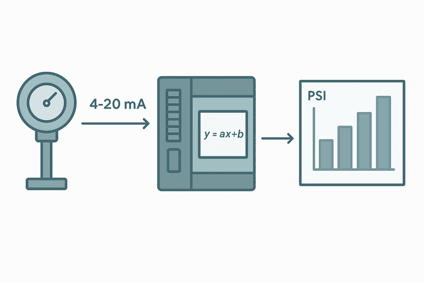
The raw output value the PLC writes to the channel maps to the physical signal. On the S7-1200 with a 4-20 mA range, the integer value 0 maps to 4 mA and 27648 maps to 20 mA. On the Rockwell 1769-OF4, the range is 0 to 32767 counts for 0 to 20 mA or 0 to 10 V. If you need to scale engineering units to raw counts, the 4-20 mA Scaling Formula walks through the maths, and 4-20 mA Scaling in a PLC has working Structured Text and ladder code.
Common Wiring Faults and How to Catch Them
Most analog output problems fall into a small number of categories. Knowing them saves a lot of time on commissioning.
- Output stuck at 4 mA or 0 V: Channel not enabled in software, hardware jumper not set, or module not powered. Check PLC online diagnostics first. See PLC Analog Output Faults: How to Diagnose Them for a structured walkthrough.
- Output correct at module but low at device: Excessive loop resistance dropping available voltage below compliance. Measure with a clamp meter at the device terminals. Calculate loop resistance as described above.
- Noisy or drifting output: Shield not connected, or grounded at both ends creating a ground loop. Cable routed with power cables. Fix: single-point shield grounding and cable segregation. Shielding Analog Signal Cables in PLC Panels covers the theory.
- Reversed polarity: Output reads correctly in software but field device shows maximum or no response. Swap the AO+ and AO- wires at one end (not both).
- Wrong signal type at device: Module jumpered for voltage but field device expects current, or vice versa. The field device may be damaged if a voltage source is driven into a low-impedance current input.
- Ground loop on 4-20 mA loop: The field device has its own chassis ground that differs in potential from the panel ground. Use a galvanically isolated analog output channel or an inline signal isolator/repeater.
Grounding, Shielding and Segregation Rules
Analog outputs are just as susceptible to noise pickup as analog inputs, especially in environments with VFDs, contactors and high-frequency switching. The grounding hierarchy matters: the Control Panel Grounding guide explains the full panel grounding scheme. For analog wiring specifically:
- Keep analog wiring in a separate cable tray or duct from 24 VDC digital I/O and completely separate from 230 VAC or motor power cables.
- Ground the shield drain wire at the panel end to a dedicated instrument ground (IG) bus bar that connects to the main protective earth at one point only.
- Never use the 24 VDC power supply 0 V rail as an instrument ground. It carries return current from digital outputs, relays and solenoids, and that current will inject noise into your analog signal.
- If the module has a functional earth (FE) terminal separate from the 0 V (M) terminal, use it. It connects internally to the module's shield circuit.
- For very long cable runs or installations near large drives, consider a galvanically isolated output module or an external signal isolator. A few euros for an isolator saves hours of noise hunting.
The PLC Analog Input Wiring guide covers the input side of the same loop in equal detail, and reading both together gives you a complete picture of a 4-20 mA instrumentation loop end to end.
Analog Output to VFD Speed Reference: A Practical Note
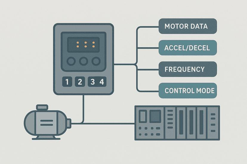
Wiring a PLC analog output to a VFD speed reference is one of the most common analog output applications. A few things catch people out. First, most drives need the analog input common (AI COM) tied to the drive's internal 0 V reference, not left floating. Second, if your drive has a jumper to select 4-20 mA or 0-10 V on the analog input, it must match the PLC output mode. Third, some drives invert the signal internally: a parameter called analog input minimum frequency or minimum speed maps the low end of the signal range. If the motor runs at full speed when you command zero, the input is probably inverted. Check the relevant frequency and analog input parameters before assuming a wiring fault.
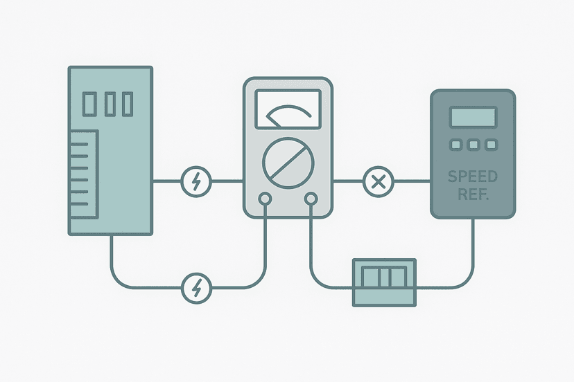
For diagnostics when the drive does not respond to your analog output, the same approach used in PLC I/O Fault Diagnosis with a Multimeter works well: measure at the module terminals, then at the drive terminals, and narrow the fault to the module, the cable, or the drive input circuit.
Keep Learning
Now that your analog output wiring is solid, the next step is making sure the PLC program scales the raw output counts into the correct engineering units and handles fault states cleanly. 4-20 mA Scaling in a PLC has working Structured Text and ladder code for both Siemens and Rockwell. If you are seeing unexpected output behaviour at runtime, PLC Analog Output Faults: How to Diagnose Them gives you a systematic fault-finding path. And if the panel grounding behind your analog wiring is not already set up correctly, start with Control Panel Grounding: The Right Way to Do It before anything else.
Frequently asked questions
What is the maximum load resistance for a 4-20 mA analog output?
Do I need an external power supply for a 4-20 mA output?
Can a PLC analog output be wired for both 4-20 mA and 0-10 V at the same time?
Should I ground the shield on an analog output cable?
Why does my 4-20 mA output read correctly at the PLC but the valve barely moves?
What causes a PLC analog output channel to drift or become noisy?
How do I test a 4-20 mA analog output without the field device connected?
What is the difference between a 2-wire and 4-wire analog output?
Can I use a 0-10 V output to drive a VFD speed reference?
What happens if I wire an analog output in reverse polarity?
Learn this by building it
There is a PLC in this site. It runs a real scan engine, checks your logic against the same tests a working machine would fail, and needs no download and no account.
Open the exercisesFree, no signup, runs in your browser. See all 16 exercises.
Was this helpful?