PLC Counter Reset: 4 Methods and When to Use Each
Counter reset logic trips up more engineers than the counting itself. The CTU or CTD instruction is usually fine. The reset is where batches get miscounted, where alarms stay latched after an operator clears them, and where a power blip wipes a shift's worth of production data. Getting the reset right matters as much as getting the count right.
What Is a PLC Counter Reset?
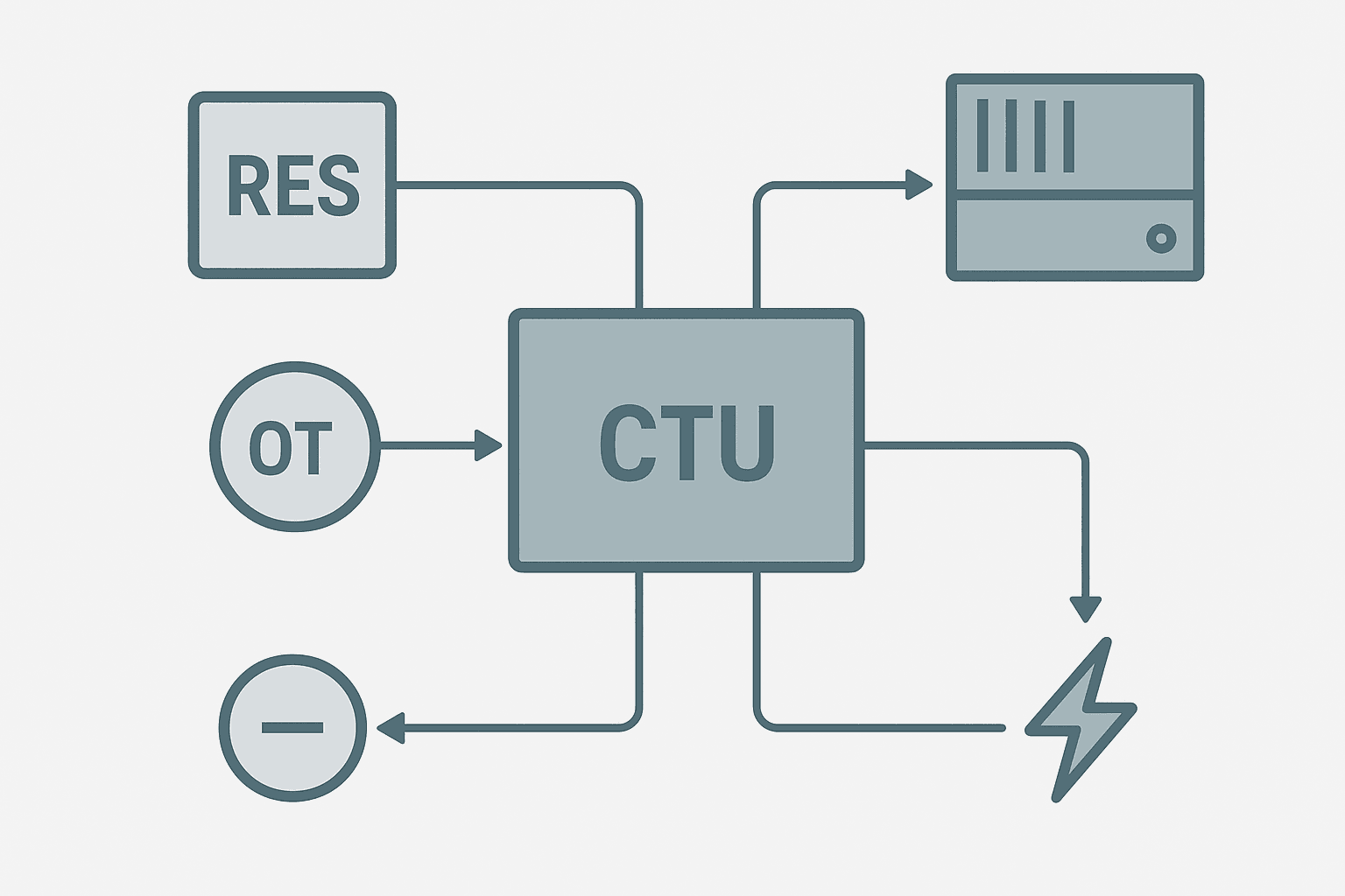
A PLC counter reset is any mechanism that forces the counter's accumulator back to a defined value (usually zero) and clears its status bits. The reset can be triggered by a ladder instruction, a hardware input, an HMI command, or a power cycle. Each method has different timing, retention, and scan-order behaviour, so choosing the wrong one produces subtle count errors that only show up mid-production.
The 4 Main PLC Counter Reset Methods
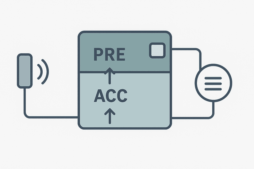
Before looking at each method, it helps to understand what a reset actually clears. In Studio 5000 Logix, a CTU tag is a structured data type. The key members are .ACC (the running count), .PRE (the preset value), .DN (done bit, true when ACC >= PRE), and .OV (overflow bit). A full reset clears .ACC to zero and drops .DN and .OV. The .PRE value is never touched by a reset. If you need a refresher on how those fields work, the post on PLC Counter Preset vs Accumulator covers them in detail.
Method 1: RES Instruction (the Standard Rockwell Approach)
The RES (Reset) instruction in Studio 5000 takes a single operand: the counter tag. When the rung goes true, it zeros .ACC and clears .DN and .OV. It works on timers too, which is why you will see it all over ladder programs. The rung condition is what makes it controllable. You wire your reset trigger (a pushbutton, an HMI bit, a shift-end flag) in series before the RES box.
Method 2: Writing Directly to the Accumulator Tag
In Logix, you can MOV 0 into MyCounter.ACC directly. This is handy when you want to preload a CTD counter to a specific value rather than zero, or when you need to do it from a Structured Text section in the same program. The structured text guide for TIA Portal shows a similar pattern for Siemens counters where you assign to the CV output variable directly. The downside in ladder is that a direct MOV does not clear the .DN bit automatically on all firmware versions, so pair it with a RES on the next rung to be safe.
Method 3: The Counter's Built-In Reset Input (IEC Platforms)
On IEC 61131-3 platforms like CODESYS, Omron Sysmac, and Siemens TIA Portal, counter function blocks expose a dedicated reset input pin (R or RESET) on the block face. Drive it true and the counter clears. This is cleaner than a separate RES rung because the reset is visually tied to the counter block. In Siemens, the CTU_INT block's R input resets CV to zero when true. If the R input stays true, the counter is held at zero and cannot count. That is usually what you want for a held-down reset button, but it catches people out when they wire a latched reset signal without realising it is keeping the counter frozen.
The Omron Sysmac Studio getting-started guide shows the IEC block face layout if you want to see what this looks like in practice. The GX Works3 guide covers the same concept on Mitsubishi hardware.
Method 4: Power Cycle (Non-Retentive Default)
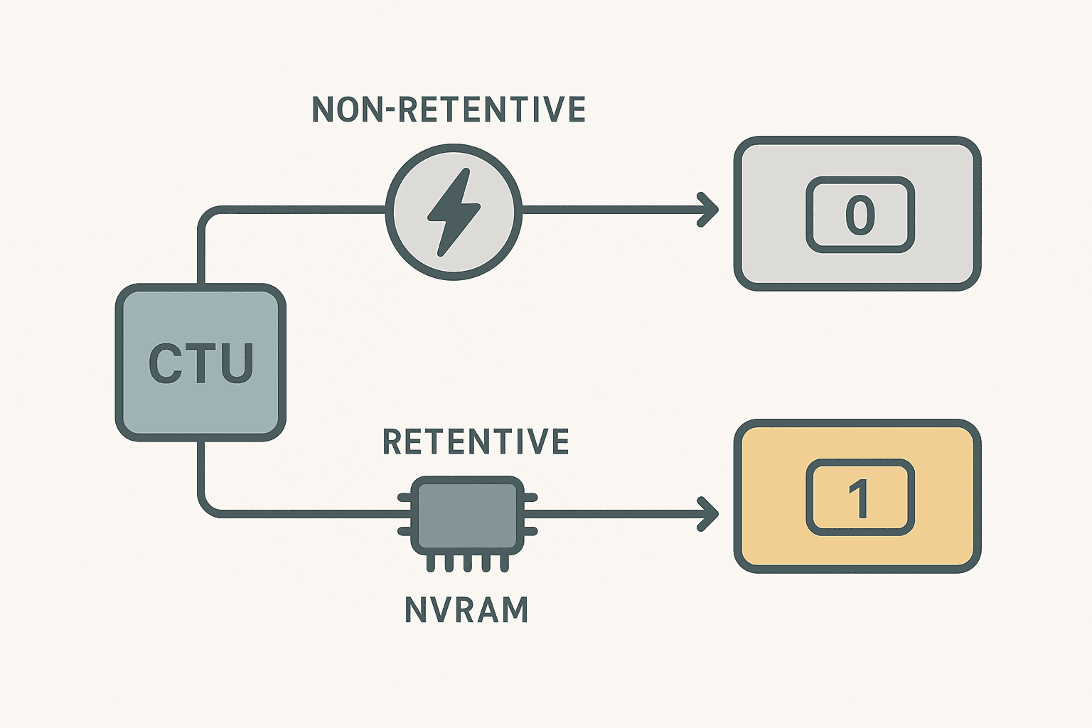
Most PLCs clear non-retentive data on power cycle. In Logix, counter tags declared in standard program-scoped or controller-scoped data are non-retentive unless you explicitly mark them retentive. So a power blip resets every counter in the program. That is fine for a cycle counter that should start fresh each shift. It is a disaster for a parts-produced counter that maintenance needs to read after an emergency stop.
The fix is to either use retentive data (mark the tag retentive in the tag properties, or store it in a NVRAM-backed data file on older ControlLogix) or to write the accumulator to an HMI or historian on a timed basis so you can restore it manually after a restart. For anything production-critical, treating the power-cycle reset as your only strategy is asking for trouble. This same principle applies to timers, which is covered in detail in the post on retentive vs non-retentive PLC timers.
Choosing the Right Reset Method: A Quick Decision Table
| Scenario | Best Reset Method | Watch Out For |
|---|---|---|
| Batch complete, start fresh next batch | RES after OSR on batch-done bit | Scan order: RES must follow CTU rung |
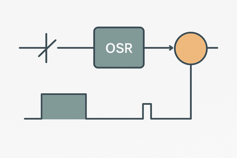
| Operator pushbutton reset on panel | RES conditioned on pushbutton XIC | Debounce the button with an OSR to avoid double-clear |
| HMI reset button on SCADA screen | RES conditioned on HMI BOOL tag plus OSR | HMI bit must be cleared after one scan; latch-and-clear pattern |
| CTD reload to preset (magazine refill) | MOV preset value to .ACC, then RES | RES alone zeros .ACC, not reload to preset |
| Shift-end total must survive power loss | Retentive tag or periodic write to historian | Non-retentive default will wipe count on any power blip |
Ladder Example: Batch Counter with HMI Reset and Shift Total Backup
This is the pattern I use most on packaging lines. The CTU counts good parts from a photo-eye. An OSR on the sensor prevents double-counting if the part lingers in the beam. When the batch preset is reached, a latch alarm goes to the HMI. The operator acknowledges, which fires the RES. A separate retentive DINT accumulates total parts for the shift without ever being reset by the batch logic.
Batch CTU with HMI Reset and Separate Shift Total (Studio 5000). Ladder logic (6 rungs): Rung 0: examine if PhotoEye_Good_Part is on (XIC), then examine if Part_OS is on (XIC), then examine if Batch_Complete_Latch is off (XIO), then CTU on Batch_Counter. Rung 1: examine if Batch_Counter.DN is on (XIC), then examine if Batch_DN_OS is on (XIC), then latch output Batch_Complete_Latch (OTL). Rung 2: examine if Batch_Complete_Latch is on (XIC), then energize output HMI_BatchAlarm (OTE). Rung 3: examine if Batch_Complete_Latch is on (XIC), then examine if HMI_BatchAck is on (XIC), then unlatch output Batch_Complete_Latch (OTU), then either RES on Batch_Counter. Rung 4: examine if Part_OS_Bit is on (XIC), then ADD on Shift_Total. Rung 5: examine if HMI_ShiftReset is on (XIC), then examine if HMI_ShiftResetConfirm is on (XIC), then MOV on 0. Rung 1: Photo-eye rising edge increments Batch_Counter only while no batch alarm is active. Rung 2: When accumulator reaches HMI_BatchPreset, a one-shot latches the alarm. Rung 3: Alarm drives the HMI indicator. Rung 4: Operator acknowledges on HMI, which clears the latch and fires RES to zero Batch_Counter. Rung 5: Every good part also adds 1 to Shift_Total (a retentive DINT), keeping a running shift count independent of batch resets. Rung 6: Shift_Total only clears when the supervisor presses both ShiftReset and ShiftResetConfirm simultaneously, preventing accidental wipes.
Common Mistakes That Cause Counter Reset Problems
- Resetting on every scan instead of one scan. If the reset condition stays true for multiple scans (like a latched HMI bit), the counter clears every scan and can never accumulate. Always use an OSR or a one-shot contact before the RES instruction unless you specifically want a held-zero.
- Forgetting that RES also clears .OV. The overflow bit signals that the accumulator wrapped past the integer maximum. If you are using .OV for diagnostics, a RES wipes that evidence. Capture .OV to a separate latch before resetting if you need to log it.
- Resetting a CTD and expecting the accumulator to reload to the preset. It does not. RES zeros the accumulator. Use a MOV instruction with the preset value to reload it, or use the CTUD instruction which has a dedicated load input.
- Not accounting for power-cycle reset on a production total counter. Test this explicitly during commissioning by cycling power with a mid-batch count and confirming whether the count survives.
- Wiring a physical reset pushbutton directly to the counter's hardware reset input on older modular PLCs. This bypasses all the software interlocks and handshaking you built. Use a digital input feeding a BOOL tag in the program instead, so the reset goes through your logic.
Resetting Counters in TIA Portal vs Studio 5000
The concept is identical but the syntax differs. In TIA Portal, the CTU function block exposes an R (reset) input. Drive it with a BOOL signal and CV resets to zero. There is no standalone RES instruction. You can also write directly to the CV output variable in a data block if you know its address, which is exactly the kind of thing that becomes important when you understand TIA Portal data blocks. In Studio 5000, the RES instruction is the standard tool. Both approaches achieve the same result; the difference is just where the reset logic lives visually.
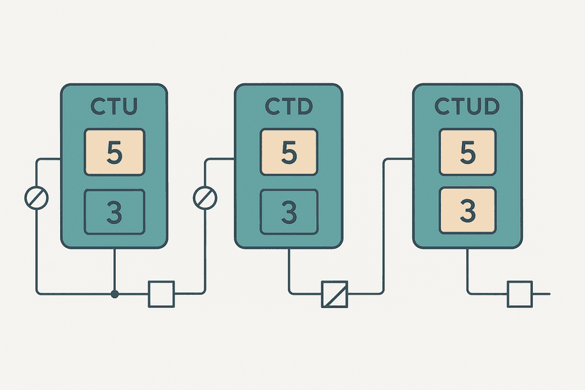
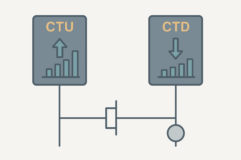
It is also worth knowing that the CTU vs CTD comparison post covers how reset behaviour differs between up-counting and down-counting instructions specifically, and the CTU, CTD and CTUD overview explains the CTUD's combined load and reset inputs that replace separate MOV and RES rungs.
Monitoring Counter Resets During Troubleshooting
If a counter is resetting unexpectedly in production, the first thing to do is go online and watch the RES rung in real time. In Studio 5000, right-click the counter tag and add it to a watch window: you will see .ACC, .PRE, .DN, and .OV live. If the accumulator is bouncing to zero in short bursts, your reset condition is flickering true for one scan. An online monitoring session with cross-reference active will show you every rung that references the counter tag, which makes finding a rogue reset condition fast.
If the counter resets at power-up only, check whether the tag is retentive and whether your startup logic has an unconditional RES on the first scan. A lot of programmers add startup initialisation rungs that zero all counters on the first scan after a power cycle, which is fine for cycle counters but wrong for production totals. Use the PLC scan cycle explanation as a reference for understanding first-scan behaviour if you are not sure when those initialisation rungs fire.
Keep Learning
Counter reset logic sits right at the intersection of counting, latching and scan-order behaviour. If you want to go deeper on the instructions themselves, the PLC counter instructions overview covers CTU, CTD and CTUD side by side. For the preset and accumulator fields in detail, the counter preset vs accumulator post is the logical next step. And if you are building batch logic that combines counters with timers, the cascading PLC timers guide shows how to chain the two instruction types cleanly.
Frequently asked questions
How do you reset a CTU counter in Studio 5000 ladder logic?
Does a PLC counter reset automatically when it reaches the preset?
What is the difference between RES and OTU for resetting a counter?
Does a CTU counter retain its value through a power cycle?
What happens if a RES instruction fires at the same time as a CTU count pulse?
How do I reset a CTD countdown counter back to its preset value?
Can I use a counter's .DN bit to auto-reset the counter on the same rung?
Now build it
You have just read about RES and CTU and CTD. Reading a rung and making one behave are different skills, and the second one is the job.
Batch Counter (CTU + RES)
Intermediateabout 15 minCount parts passing a sensor; after 4 parts the batch is done and a lamp turns on. A reset button starts the next batch. Counters count RUNG EDGES: a part sitting on the sensor counts once, not forever.
Build this rungFree, no signup, runs in your browser. See all 16 exercises.
Was this helpful?