Cascading PLC Timers: Chain TON Logic Right
You need a three-step chemical rinse: pre-rinse for 10 seconds, soak for 30 seconds, final rinse for 15 seconds. Each step only starts after the previous one finishes. This is one of the most common timed-sequence problems in industrial automation, and cascading PLC timers is the cleanest way to solve it in ladder logic.
What Are Cascading PLC Timers?
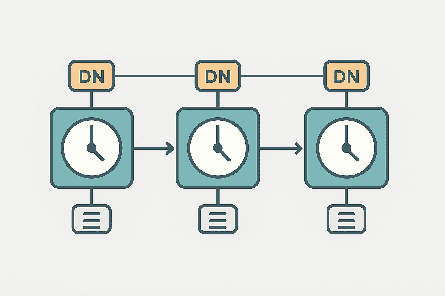
Cascading PLC timers means using the done bit of one TON timer as the enable condition for the next TON timer in the sequence. When Timer 1 finishes, its DN (or Q) bit goes TRUE and enables Timer 2. When Timer 2 finishes, its DN bit enables Timer 3. Each stage runs for exactly its preset time, back to back, driven entirely by the timer outputs themselves. No extra state machine, no integer step counter, just timer bits feeding timer rungs.
Why Cascade Timers Instead of Using One Long Timer?
The obvious alternative is one big TON set to the total time, with comparison instructions checking the accumulated value to decide which output to energise. That works, but it has real downsides. You can't adjust individual step times without recalculating offsets. Adding a step means touching every comparison value. And when you're staring at it at midnight during a commissioning, a chain of named timers (PreRinse_Timer, Soak_Timer, FinalRinse_Timer) is a lot easier to follow than GRT(Cycle_Timer.ACC, 10000) scattered across rungs.
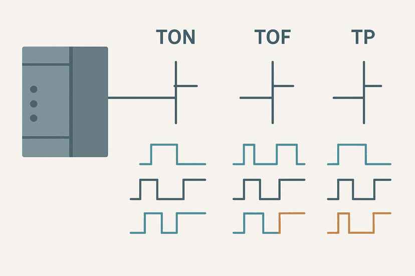
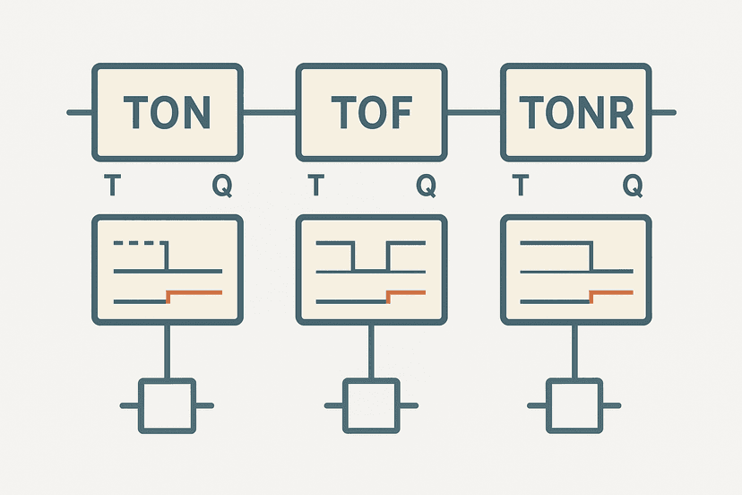
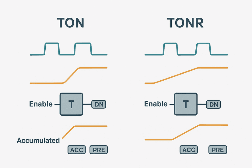
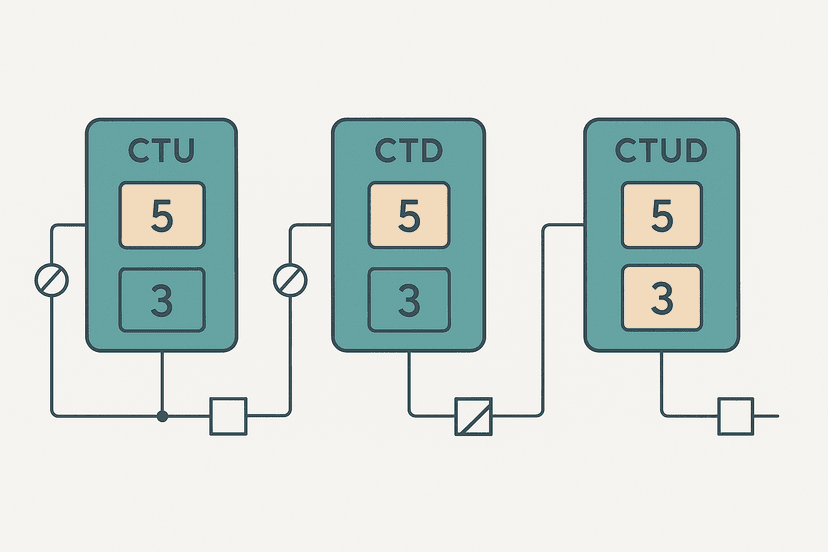
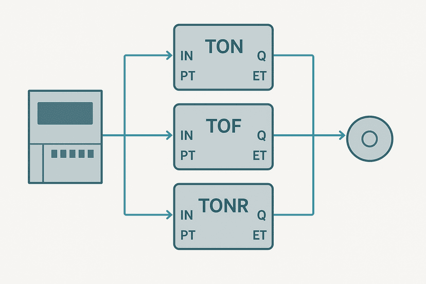
Cascaded timers also pair naturally with the PLC counter instructions you might already have tracking batch cycles, and they fit cleanly into the same rung structure you learned when studying TON, TOF and TONR differences.
The Basic Cascade Pattern: Three Rungs, Three Timers
Here is the skeleton of a three-step cascade in Studio 5000 notation. Timer presets are in milliseconds.
| Rung | Enable Condition | Timer Tag | Preset (ms) | Output Coil |
|---|---|---|---|---|
| 1 | Seq_Start XIO(Seq_Fault) | PreRinse_Timer | 10000 | PreRinse_Sol |
| 2 | PreRinse_Timer.DN | Soak_Timer | 30000 | Soak_Sol |
| 3 | Soak_Timer.DN | FinalRinse_Timer | 15000 | FinalRinse_Sol |
| 4 | FinalRinse_Timer.DN | (none) | (none) | Seq_Complete |
Rung 1 starts the moment Seq_Start goes TRUE (and no fault is active). Rung 2 is not enabled until PreRinse_Timer.DN fires. Rung 3 waits for Soak_Timer.DN. The output coil on each rung gives you the physical signal to drive your solenoid valve or contactor for that step.
PreRinse_Timer tells you everything; Timer3 tells you nothing at 2 a.m. when the machine is faulted.Cascading PLC Timers: Interactive Ladder Example
3-Step Wash Sequence: Cascaded TON Timers (Studio 5000). Ladder logic (10 rungs): Rung 0: examine if Wash_Start is on (XIC), then examine if Wash_FaultLatch is off (XIO), then examine if FinalRinse_Timer.DN is off (XIO), then TON on PreRinse_Timer. Rung 1: examine if PreRinse_Timer.DN is on (XIC), then examine if Wash_FaultLatch is off (XIO), then TON on Soak_Timer. Rung 2: examine if Soak_Timer.DN is on (XIC), then examine if Wash_FaultLatch is off (XIO), then TON on FinalRinse_Timer. Rung 3: examine if PreRinse_Timer.DN is on (XIC), then examine if Soak_Timer.DN is off (XIO), then energize output PreRinse_Sol (OTE). Rung 4: examine if Soak_Timer.DN is on (XIC), then examine if FinalRinse_Timer.DN is off (XIO), then energize output Soak_Sol (OTE). Rung 5: examine if FinalRinse_Timer.DN is on (XIC), then energize output FinalRinse_Sol (OTE). Rung 6: examine if FinalRinse_Timer.DN is on (XIC), then examine if Seq_Done_OS is on (XIC), then CTU on Wash_Cycle_Count. Rung 7: examine if Wash_Start is on (XIC), then TON on Wash_Timeout. Rung 8: examine if Wash_Timeout.DN is on (XIC), then examine if FinalRinse_Timer.DN is off (XIO), then examine if Timeout_OS is on (XIC), then latch output Wash_FaultLatch (OTL). Rung 9: examine if Wash_FaultLatch is on (XIC), then examine if HMI_FaultAck is on (XIC), then examine if Wash_Start is off (XIO), then unlatch output Wash_FaultLatch (OTU). Rungs 1-3 chain three TON timers. Each solenoid output (rungs 4-6) is ON only during its own step: PreRinse_Sol is ON from Timer1.DN to Timer2.DN, keeping it clean. Rung 7 increments a cycle counter on the rising edge of sequence completion. Rungs 8-10 add a 70-second overall timeout fault latch as a safety net in case any timer hangs.
The diagram above evaluates one scan. Run these exact rungs on a real scan cycle to watch the latching and the timers behave.
Run this in the simulatorThe Output Overlap Trick Most Guides Skip
Notice rungs 4 to 6 in the example above. Instead of using each timer's own enable condition to drive the solenoid, the outputs use XIC(ThisTimer.DN) XIO(NextTimer.DN). That means PreRinse_Sol turns ON the moment PreRinse_Timer.DN fires and turns OFF the moment Soak_Timer.DN fires. You get a clean, exactly-bounded pulse for each step with no overlap and no gap.
If you just use XIC(Wash_Start) for PreRinse_Sol, the solenoid stays energised through all three steps because Wash_Start never drops. I've seen that exact mistake on a bottle-washing cell where the pre-rinse valve was staying open through the chemical soak, diluting the detergent. The machine ran for two weeks before anyone noticed the wash quality dropping.
Resetting the Sequence: What You Need to Know
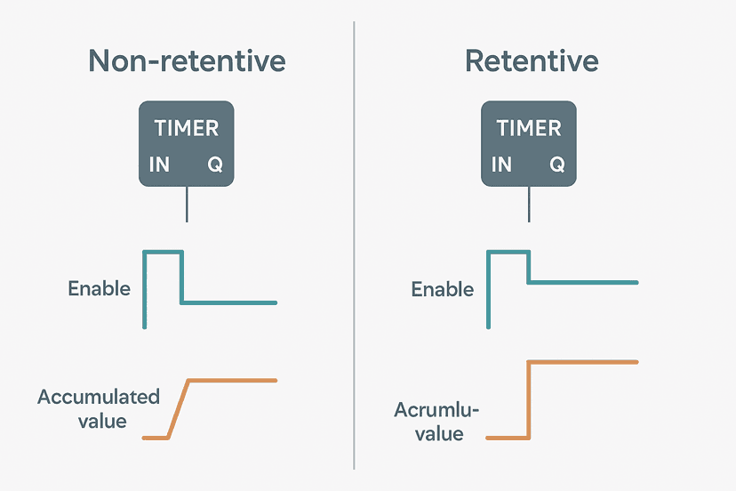
Non-retentive TON timers in Logix reset automatically when their enable rung goes FALSE. So when Wash_Start drops out (operator presses Stop, or an E-stop fires), all three timers reset immediately. You don't need explicit RES instructions for a normal stop.
But there's a catch. Notice the XIO(FinalRinse_Timer.DN) contact on rung 1 in the example. Without it, once FinalRinse_Timer.DN is TRUE, the enable rung for PreRinse_Timer stays TRUE (assuming Wash_Start is still asserted), and the whole sequence immediately re-triggers. That extra XIO contact breaks the re-trigger loop and forces the operator to release and re-assert Wash_Start to run another cycle. This is the most common bug I see in student and junior-engineer cascade implementations.
Adding a Sequence Timeout Fault
Rungs 8 to 10 in the example add a 70-second overall watchdog timer. The total of the three steps is 55 seconds, so 70 seconds gives a comfortable margin. If the sequence hasn't completed by then (because a valve is stuck open or a sensor lied), the timeout fires a fault latch and shuts everything down. This is the same pattern described in the PLC timer ladder logic examples article, and it's non-negotiable on any sequence that controls fluids or heat.
For the fault latch itself, the OTL/OTU pattern keeps the alarm visible even after the start condition drops. If you're not familiar with latching coils, the OTL and OTU latch coil guide covers the mechanics in detail.
How the Scan Cycle Affects Cascade Timing
Each timer's DN bit goes TRUE during the scan in which the accumulated value first reaches the preset. The next timer's enable rung sees that TRUE bit one full scan later. On a typical 10 ms scan cycle this is invisible. On a slow scan (50 ms or more), you'll see a one-scan gap between steps. For most wash and soak applications this is fine. For tight electromechanical sequences, consider moving the cascade to a faster task or tightening your scan time. The PLC scan cycle troubleshooting article has the details if you're chasing timing errors.
Siemens TIA Portal: The Same Logic, Different Syntax
The cascade principle is identical in TIA Portal. You use IEC TON function blocks with instance data blocks. Timer 1's Q output connects to the IN pin of Timer 2, and so on. The tag names follow the pattern PreRinse_Timer.Q instead of PreRinse_Timer.DN. If you are working on an S7-1200, the S7-1200 timers guide walks through the instance DB naming and the subtle difference in how TIA Portal IEC timers handle the PT (preset time) input.
When to Stop Cascading and Use a Sequencer Instead
Cascaded timers are clean up to about four or five steps. Beyond that, the rung count grows fast and adding or reordering steps becomes error-prone. If you have more than five timed steps, different step times for different product recipes, or steps that can be skipped based on a sensor, you want a proper step sequencer: an integer step counter, an array of preset times, and a CTU advancing the step on each DN bit. You can see that pattern in the array-indexed sequencer already published in the 3-motor start sequence exercise.
For applications that do need recipe-based timing, you might also look at how the PLC bottle filling machine project handles variable fill times alongside timed sequences. The underlying cascade structure is the same, but recipe values replace hard-coded presets.
Common Mistakes Summary
- Forgetting XIO(LastTimer.DN) on the first rung, causing infinite auto-repeat.
- Driving solenoid outputs from the start condition instead of the timer window (XIC(ThisDN) XIO(NextDN)), causing overlapping valve opens.
- No overall timeout watchdog. A stuck valve or wiring fault leaves the sequence running indefinitely.
- Using TONR (retentive) timers in a cascade without explicit RES instructions. The accumulated value survives a power cycle and the sequence jumps ahead on restart.
- Chaining more than five steps without switching to a step counter, making the program nearly unreadable in six months.
- Not testing what happens when the start condition drops mid-sequence. The auto-reset behaviour of TON is your friend here, but only if you understand it.
If you are ever debugging a cascade that behaves unexpectedly, the PLC troubleshooting with online monitoring article shows exactly how to watch timer accumulated values update in real time without stopping the program. And if you want to test a cascade before wiring up real hardware, simulating ladder logic without a PLC gives you options for every major platform.
Keep Learning
Once you are comfortable cascading TON timers, the natural next step is understanding how retentive and non-retentive timers differ so you know when TONR changes your reset strategy. You might also want to study the TON vs TOF vs TP comparison to see how a TOF cascade works for controlled shutdown sequences. For bigger multi-step projects that go beyond pure timer logic, the PLC pump station exercise and the car wash PLC exercise both use timed sequences you can adapt directly.
Frequently asked questions
What does cascading PLC timers mean?
Can you chain more than two TON timers in ladder logic?
Why does my second timer start immediately even before the first one finishes?
Should I reset earlier timers when the sequence ends?
What is the difference between cascading timers and a step sequencer?
Do cascading timers work the same way in Siemens TIA Portal?
How do I add a fault timeout to a cascaded timer sequence?
Can I use TOF timers in a cascade?
Now build it
You have just read about XIO and OTL and OTU. Reading a rung and making one behave are different skills, and the second one is the job.
State Coil / Fault Coil
Intermediateabout 15 minA fault lamp that latches ON when any alarm condition occurs, even briefly, and only clears on Reset. And if the condition is still present when Reset is released, the fault comes right back.
Build this rungFree, no signup, runs in your browser. See all 16 exercises.
Was this helpful?