CTU vs CTD: PLC Counter Instructions Compared
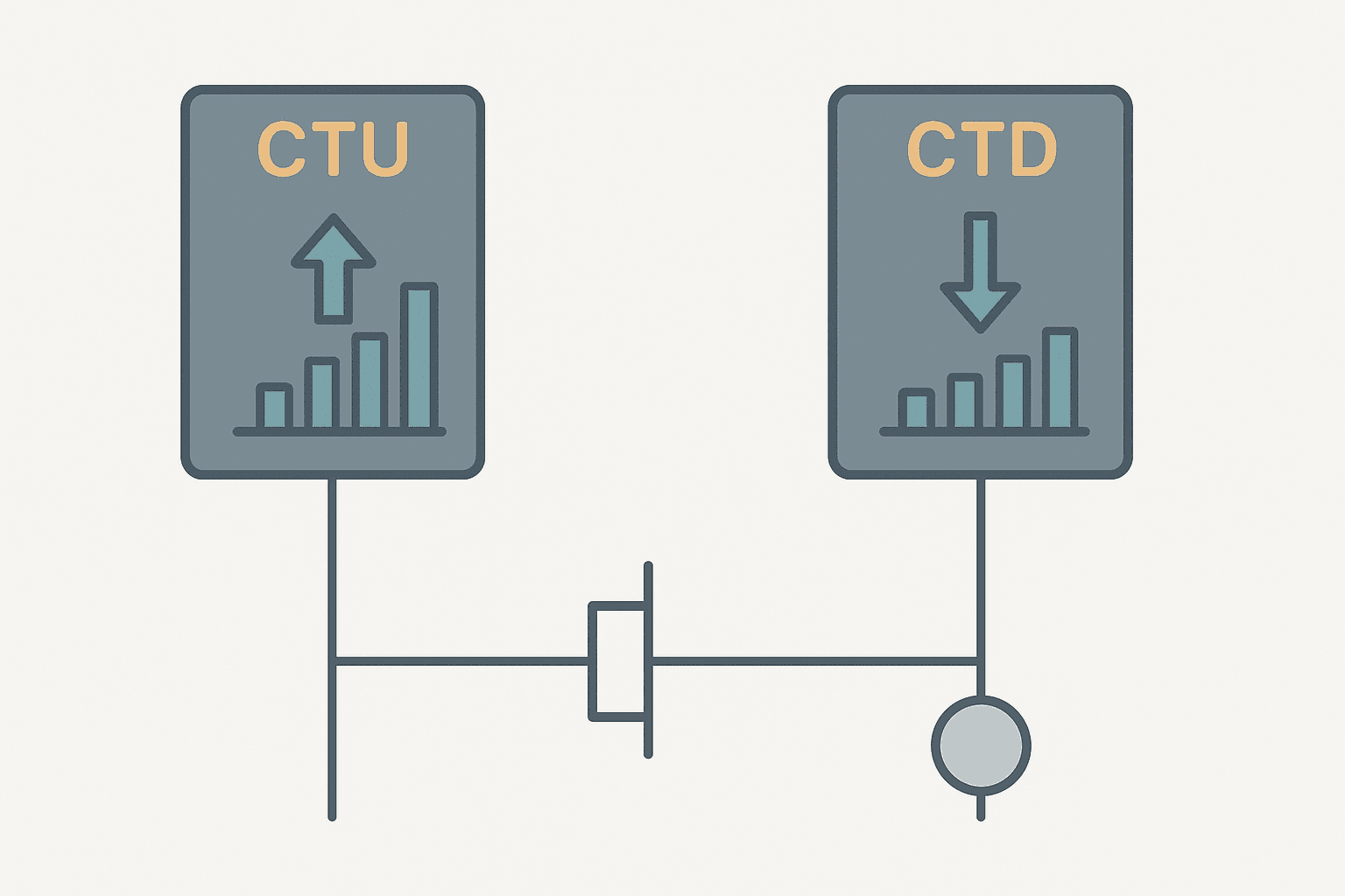
CTU and CTD are the two most fundamental counter instructions in PLC ladder logic. They look almost identical on a rung, they share the same basic parameters, and yet they count in opposite directions and solve different problems. Picking the wrong one does not usually cause a crash, but it does make your logic harder to read and your HMI displays confusing. This post lays out exactly how each instruction works, where each one fits best, and what to watch out for in the real world.
What Is CTU vs CTD in a PLC?
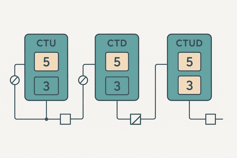
CTU (Count Up) and CTD (Count Down) are IEC 61131-3 counter function blocks used in PLC ladder logic. CTU increments its accumulated value by one on each rising edge of its count input and sets its done output when the accumulated value reaches the preset. CTD decrements from a loaded preset toward zero and sets its done output when the accumulated value reaches zero. Both instructions require an explicit reset to clear the accumulated value and allow reuse.
How CTU Works: Counting Up to a Target
CTU starts at zero and counts toward a preset value you define. Each false-to-true transition on the count input adds one to the accumulated value. When accumulated equals preset, the done bit (DN in Rockwell, Q in IEC/Siemens) turns on. The accumulated value keeps climbing past the preset if you do not reset it, so leaving a reset path out of your rung is a real bug waiting to happen.
In Studio 5000, a CTU uses a COUNTER data type tag. The three members you touch most are PRE (the target count), ACC (the running total), and .DN (the done bit). There is also an overflow bit .OV that sets if ACC wraps past the DINT ceiling, though you will rarely see that outside a very long-running production counter with no reset. For a deep look at all three counter instructions together, the post on PLC Counter Instructions: CTU, CTD and CTUD Explained covers the full picture.
How CTD Works: Counting Down to Zero
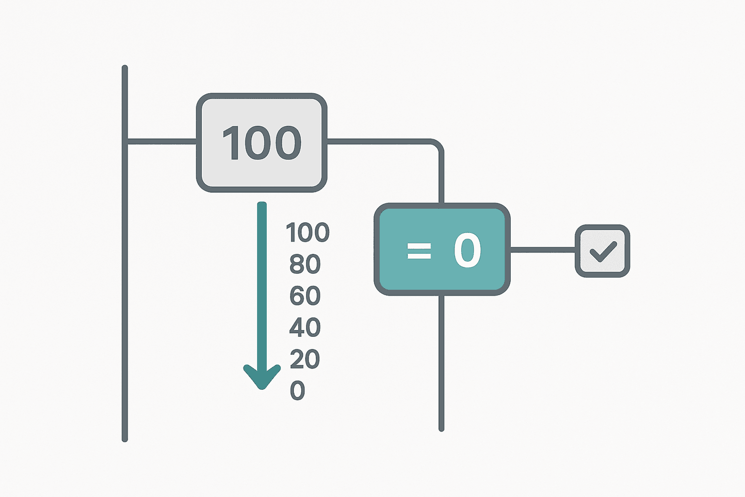
CTD works in reverse. You load a preset and the accumulated value decrements by one on each rising edge. The done bit sets when ACC reaches zero. On Rockwell Logix, the CTD done bit is .DN just like CTU. On Siemens S7-1200 using the IEC CTD block, the output is Q, and it goes true when CV (current value) is less than or equal to zero.
The CTD load input is important and often overlooked. Before counting down, you need to load the preset into the accumulated value. In Rockwell Logix, a separate MOV instruction into the counter.ACC before enabling the count is the standard approach. In Siemens IEC CTD, there is a dedicated LD (load) input on the function block: drive it true and PV (preset value) gets copied into CV automatically. Miss the load step and your CTD starts from whatever leftover value is in ACC, which is a classic first-time mistake.
CTU vs CTD: Direct Comparison
| Parameter | CTU | CTD |
|---|---|---|
| Direction | Counts up (ACC increases) | Counts down (ACC decreases) |
| Done condition | ACC >= PRE | ACC <= 0 |
| Starting ACC value | 0 (after reset) | Loaded from PRE or MOV |
| Load input needed? | No | Yes (LD on IEC; MOV in Logix) |
| Reset clears ACC to | 0 | 0 (IEC) or retains until next load |
| Overflow risk | Yes, if no reset and counts continue | Underflow if ACC goes below 0 (platform-dependent) |
When to Use CTU vs CTD: Real Application Examples
Use CTU when you are accumulating toward a target
CTU is the natural fit any time you are building up to something. Counting parts on a conveyor to trigger a box full alarm, counting machine cycles to schedule maintenance, counting rejected parts to halt a line after too many failures. The HMI display of ACC naturally reads as progress: you are at 47 of 100. In the PLC Bottle Filling Machine example, a CTU tracks how many bottles a filler has completed in the current shift, with the DN bit kicking off a batch report.
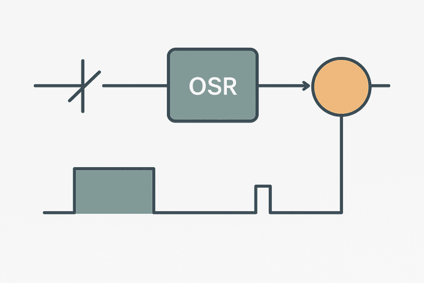
CTU also pairs cleanly with a one-shot rising edge upstream of the count input. This is important because many proximity sensors stay high for several scan cycles as a part moves past them. Without the one-shot, your CTU would count multiple times per part. The pattern is: sensor energizes, OSR fires once, CTU increments once. Done.
Use CTD when you are dispensing or depleting from a known quantity
CTD shines when the quantity to track is a remaining amount. A hopper holding 500 tablets, a reel of labels with 2000 left, a pallet with 24 carton slots still empty. You load the known quantity into the preset, count down as items are used, and the done bit fires when stock is gone. The HMI shows remaining count without any math on the display side, which operators find more intuitive than watching a CTU approach its preset from below.
I used this exact approach on a tablet press commissioning years ago. The machine counted tablets dispensed into each bottle, and the customer wanted the HMI to show tablets remaining. Using CTD meant the display just read ACC directly. With CTU we would have needed a subtraction block on the HMI or in the PLC just to derive the same number. CTD saved the display math and made the logic self-documenting.
Use CTUD when both directions matter
If parts enter a buffer zone from one end and leave from another, you need a single accumulated value that both increments and decrements. That is the CTUD (Count Up/Down) instruction. It has separate CU and CD inputs but shares one ACC. A CTU and CTD on separate tags cannot do this cleanly. CTUD is covered in depth in PLC Counter Instructions: CTU, CTD and CTUD Explained if you need the full detail on that instruction.
Platform Differences You Need to Know
Rockwell Logix (Studio 5000): CTU and CTD each use a COUNTER data type. Reset uses a separate RES instruction. The done bit is .DN. Overflow is .OV, underflow is .UN. The accumulated value is a DINT, so the maximum count before overflow is 2,147,483,647, which is effectively unlimited for production counting.
Siemens S7-1200 and S7-1500 (TIA Portal): These platforms use IEC-compliant CTU and CTD function blocks from the IEC_Counter library. The data type is a multi-instance DB. CTD has a LD (load) input that copies PV into CV when true. The Q output is the done bit. The R (reset) input on CTU and the LD input on CTD are inline on the block rather than separate instructions. If you are building programs in TIA Portal, the post on S7-1200 Timers in TIA Portal shows the same IEC block pattern applied to timers, so the mental model transfers directly.
Mitsubishi GX Works3: Counter coils use C addresses (C0 to C199 for 16-bit counters). An OUT C0 K100 instruction sets the preset to 100. The counter increments each scan the coil rung is true and the input transitions, then the contact C0 closes at setpoint. Reset uses RST C0. High-speed counters use a separate HSC function. For a full walkthrough of the GX Works3 environment, see the GX Works3 Getting-Started Guide.
Omron Sysmac: CNT (count) and CNTR (reversible count) instructions handle up and down counting. The Omron Sysmac Studio Getting-Started Guide shows how the instruction set is organized if you are new to that platform.
A Practical CTD Ladder Logic Example: Parts Remaining in a Magazine
The rung below uses a CTD on a Rockwell Logix platform to track parts remaining in a feed magazine. A load command (triggered once at machine start or after a reload) moves the preset into ACC. Each time a part exits the magazine, the proximity sensor fires a one-shot, and CTD decrements. When ACC hits zero, the done bit sets a low-stock alarm and disables the feeder. The HMI reads Feeder_CTD.ACC directly as parts remaining.
CTD Magazine Parts-Remaining Counter with Low-Stock Alarm (Studio 5000). Ladder logic (5 rungs): Rung 0: examine if Feeder_ReloadCmd is on (XIC), then examine if Reload_OS is on (XIC), then MOV on 200. Rung 1: examine if PartExit_Prox is on (XIC), then examine if PartExit_OS is on (XIC), then examine if Feeder_LowStock is off (XIO), then CTD on Feeder_CTD. Rung 2: examine if Feeder_CTD.DN is on (XIC), then examine if LowStock_OS is on (XIC), then latch output Feeder_LowStock (OTL). Rung 3: examine if Feeder_LowStock is on (XIC), then examine if HMI_LowStockAck is on (XIC), then examine if Feeder_CTD.DN is off (XIO), then unlatch output Feeder_LowStock (OTU). Rung 4: examine if Feeder_LowStock is off (XIO), then examine if Sys_Running is on (XIC), then energize output Feeder_Enable (OTE). Rung 1: On a reload command rising edge, MOV loads 200 into Feeder_CTD.ACC. Rung 2: Each part-exit proximity sensor rising edge decrements the CTD by one, guarded by the low-stock flag so counting stops at zero. Rung 3: When ACC reaches zero, a one-shot latches the low-stock alarm. Rung 4: Operator acknowledge clears the latch once the magazine is refilled. Rung 5: Feeder runs only while no low-stock alarm is active.
Common Mistakes with CTU and CTD
- Forgetting to load CTD before first use: ACC starts at 0 and done fires instantly on the first scan.
- Not one-shotting the count input: a sensor held high for 5 scans gives you 5 counts instead of 1.
- Resetting too early: issuing RES in the same rung as the DN bit means the counter never stays done long enough for downstream logic to see it. Use a latch (OTL) to capture DN first.
- Mixing up CTU and CTD done conditions: CTU DN is ACC >= PRE; CTD DN is ACC <= 0. They are not symmetric, and assuming they are leads to off-by-one logic errors.
- Ignoring the overflow and underflow bits: on Logix, if ACC wraps, the OV or UN bit sets but does not fault the PLC. Your count silently corrupts. Check these bits during commissioning.
Connecting Counter Logic to the Rest of Your Program
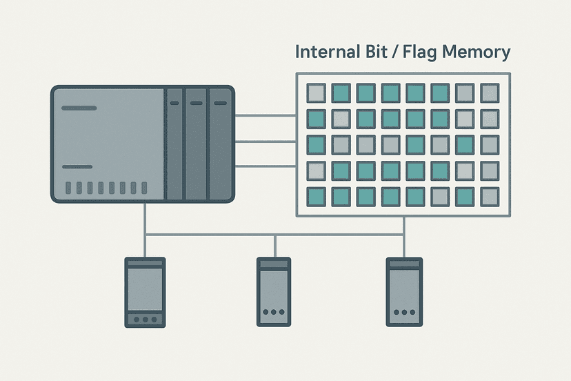
Counter done bits behave exactly like any other internal bit in your program. You can use them as contacts in other rungs, map them to HMI tags, or feed them into set-reset flip-flop logic to latch alarms. The ACC value is just an integer tag, so you can compare it against a setpoint with a GEQ or LES instruction to trigger intermediate actions before DN fires.
For a broader look at how PLC internal bits, flags and coils interact with instructions like counters and timers, that post covers the addressing side of things in detail. And if you want to see counters embedded inside a larger sequence, the PLC Pump Station Exercise and Car Wash PLC Exercise both use cycle counters as part of the complete program.
Diagnosing counter issues in a running machine is straightforward with online monitoring. The PLC Troubleshooting with Online Monitoring post walks through how to watch ACC in real time and force test inputs to verify your count logic before production starts. If you are seeing counts that seem wrong, also check whether an intermittent sensor fault is generating spurious pulses.
What to Read Next
If you want to go deeper on counter instructions, the full three-instruction breakdown in PLC Counter Instructions: CTU, CTD and CTUD Explained covers CTUD and the edge cases in detail. For related timing logic that often works alongside counters, PLC Timer Ladder Logic: 5 Practical Examples shows real working circuits you can adapt. And if you want to test any of this without physical hardware first, How to Simulate Ladder Logic Without a PLC gets you set up quickly.
Frequently asked questions
What is the difference between CTU and CTD in a PLC?
What does the CTU done bit mean?
How do you reset a CTU or CTD counter in ladder logic?
What happens if a CTU accumulated value exceeds the preset?
What is a typical use case for CTD instead of CTU?
Does CTU count every scan or only on a rising edge?
What data type does a Rockwell CTU use?
Is CTUD the same as running CTU and CTD on the same tag?
Why would a counter miss counts in a PLC program?
Now build it
You have just read about CTD and CTU and CTUD. Reading a rung and making one behave are different skills, and the second one is the job.
Batch Counter (CTU + RES)
Intermediateabout 15 minCount parts passing a sensor; after 4 parts the batch is done and a lamp turns on. A reset button starts the next batch. Counters count RUNG EDGES: a part sitting on the sensor counts once, not forever.
Build this rungFree, no signup, runs in your browser. See all 16 exercises.
Was this helpful?