PLC Counter Preset vs Accumulator: What Each Does
If you have ever stared at a CTU instruction and wondered why the done bit fired too early, or why resetting the counter did nothing useful, the answer is almost always a misunderstanding of what PRE and ACC actually do. They look similar, they sit in the same instruction block, and they interact in a way that trips up even engineers who have been writing ladder logic for years. Let's sort that out properly.
What Is the PLC Counter Preset and Accumulator?
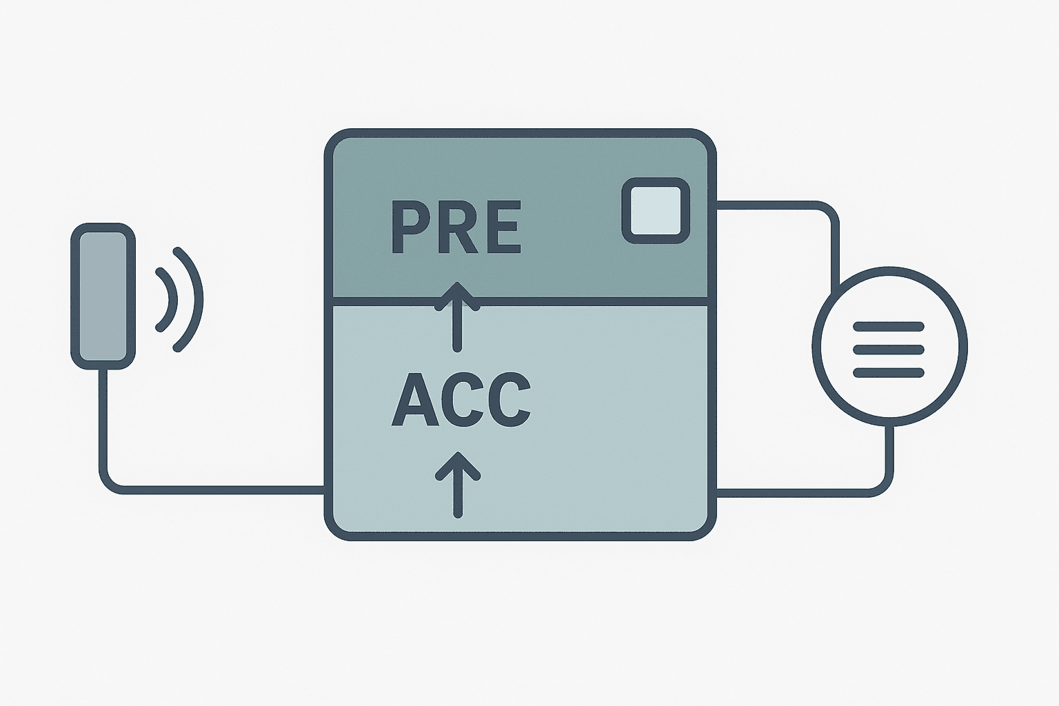
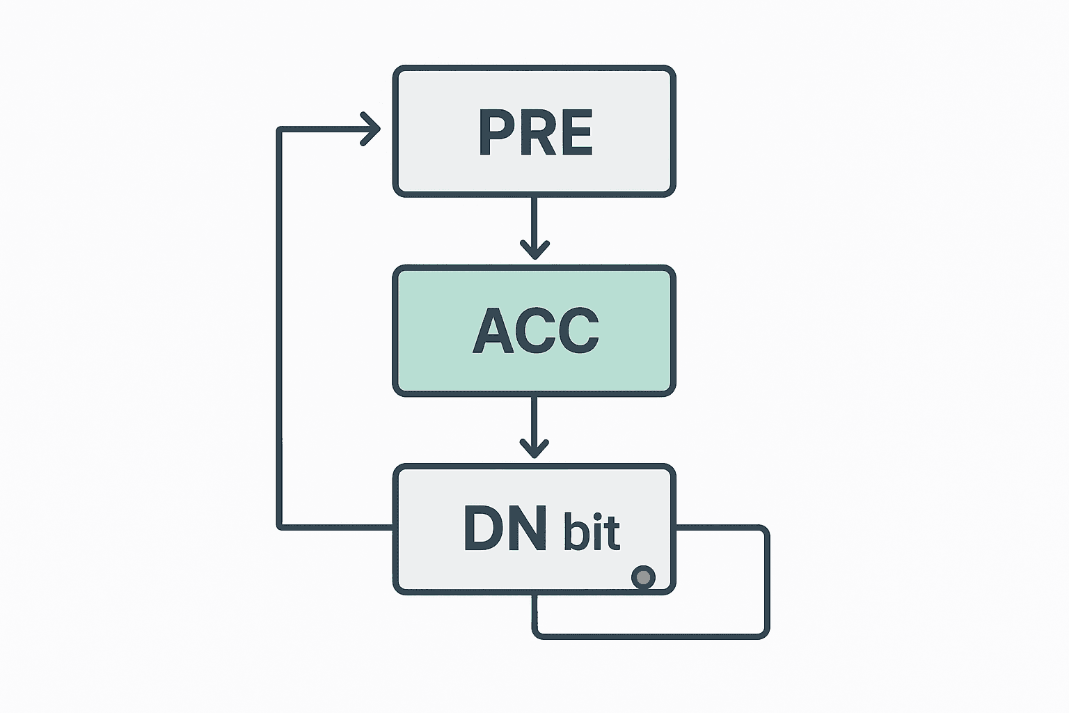
The preset (PRE) is the target count value you configure before the program runs. It is the number the counter is counting toward. The accumulator (ACC) is the live value that changes every time the counter rung transitions from false to true. When ACC reaches PRE, the done bit (.DN) energises. Think of PRE as the distance on a race track and ACC as the position of the runner. One is fixed (until you deliberately change it), the other moves every scan.
How the Preset Value Works
PRE is a static integer you enter at program time. In Studio 5000 Logix it is stored as a DINT member of the counter structure, so it can hold values from 0 to 2,147,483,647. You can also write to it at runtime from an HMI tag or a MOV instruction, which is exactly how batch-size recipes work: the HMI writes the new target quantity into Batch_Counter.PRE before the operator hits Start.
One thing PRE does not do automatically: it does not load itself into ACC. That is a point of confusion with CTD counters especially. When you want a count-down to start from 200, you need a separate MOV to put 200 into .ACC. PRE is only a comparison target, not a starting value. The CTU vs CTD comparison post goes through this in detail if you are working with down-counters.
How the Accumulator Works
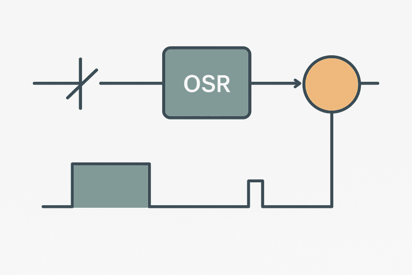
ACC increments (CTU) or decrements (CTD) by exactly one each time the rung condition transitions from false to true within a single scan. It does not fire on every scan while the rung is true: it only fires on the rising edge of the rung. That is why you will see a one-shot rising edge (OSR) upstream of a counter in some programs, though for most sensors it is redundant because the sensor signal itself changes state naturally.
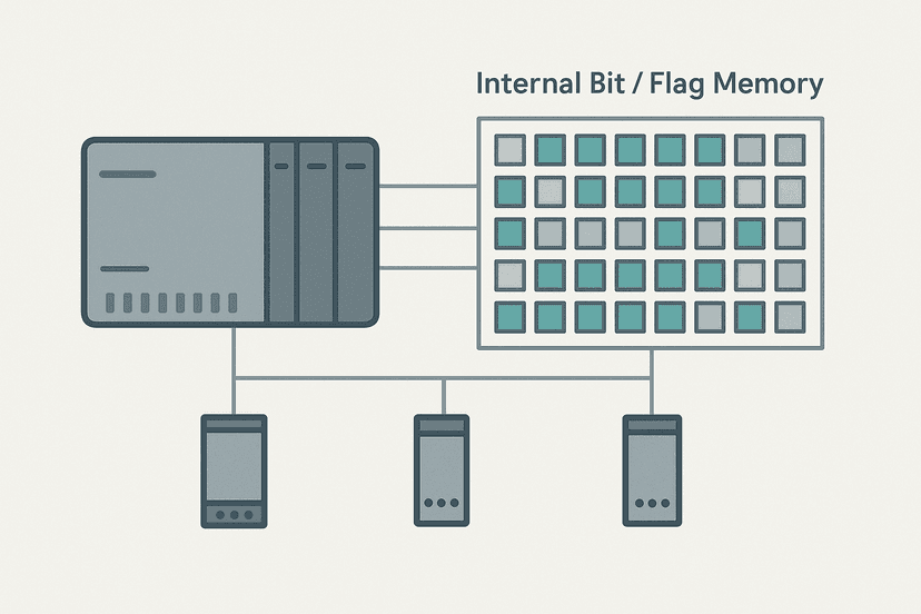
ACC holds its value between scans indefinitely, unless you reset it. It survives a program mode change in most Logix controllers. Whether it survives a power cycle depends on your tag configuration. Standard controller-scoped tags in Studio 5000 are not retentive by default; you need to store ACC to a retentive data structure or non-volatile memory if a power loss must not lose the count. Siemens S7, by contrast, retains STATIC variables in instance data blocks across a power cycle by default, so the same issue presents differently depending on the platform you are on.
You can also write directly to .ACC from outside the counter instruction. A MOV instruction targeting Batch_Counter.ACC is perfectly valid and is far more flexible than RES for pre-loading a mid-range start value. When the PLC scan cycle reaches the counter rung next time, it compares the new ACC to PRE and updates the done bit accordingly.
The Done Bit: What Actually Triggers It
The .DN bit turns on when ACC is greater than or equal to PRE. It stays on. It does not pulse for one scan and turn off. If you need a one-scan pulse when the count is reached, put a rising-edge one-shot (OSR) on the XIC of .DN. Without that, any coil driven by .DN will remain energised until you reset the counter.
The .OV (overflow) bit is the other bit worth knowing. On a CTU, if ACC exceeds the maximum DINT value it rolls over and .OV sets. In practice this means a counter that is never reset on a high-speed line can silently corrupt your count logic after millions of cycles. Always include a RES or a MOV to zero in your reset rung.
PRE vs ACC: Side-by-Side Summary
| Property | Preset (PRE) | Accumulator (ACC) |
|---|---|---|
| Purpose | Target count to compare against | Live running count |
| Who writes it | You, at program time or via HMI/MOV | The counter instruction itself (or a MOV) |
| Changes during run | Only if you explicitly write a new value | Every rung false-to-true edge |
| Effect of RES | No effect on PRE | Resets to 0, clears .DN and .OV |
| Retentive by default (Logix) | Yes, it is program data | No, unless tag type is retentive |
| Range (Studio 5000 DINT) | 0 to 2,147,483,647 | Same; wraps with .OV if exceeded |
A Real Ladder Example: Bottle Reject Counter with Dynamic Preset
The rung below counts reject pulses from a vision system. The preset is written by the HMI at recipe changeover so the alarm threshold changes per product. Notice the OSF (falling-edge one-shot) on the reject sensor: the vision trigger is a pulse that can be long enough to span more than one scan on a slow line, so the OSF guarantees exactly one count per bottle. You can read more about falling-edge detection in the OSF explained post.
Vision Reject Counter with HMI-Driven Preset and Latched Alarm (Studio 5000). Ladder logic (5 rungs): Rung 0: examine if Vision_RejectPulse is on (XIC), then examine if Reject_OS is on (XIC), then examine if Reject_CountLatch is off (XIO), then CTU on Reject_Counter. Rung 1: examine if Reject_Counter.DN is on (XIC), then examine if Reject_Alarm_OS is on (XIC), then latch output Reject_CountLatch (OTL). Rung 2: examine if Reject_CountLatch is on (XIC), then energize output HMI_RejectAlarm (OTE). Rung 3: examine if Reject_CountLatch is on (XIC), then examine if HMI_RejectAck is on (XIC), then examine if Vision_RejectPulse is off (XIO), then unlatch output Reject_CountLatch (OTU), then either RES on Reject_Counter. Rung 4: examine if HMI_ShiftReset is on (XIC), then RES on Reject_Counter, then either unlatch output Reject_CountLatch (OTU). HMI_RejectLimit is written to Reject_Counter.PRE at recipe load time. The OSR on the sensor input converts any pulse width to a single scan edge. XIO(Reject_CountLatch) stops the counter incrementing further once the threshold is hit. The operator acknowledges via HMI_RejectAck, which clears the latch and resets ACC. HMI_ShiftReset provides an independent per-shift zero.
Common Mistakes and How to Avoid Them
Mistake 1: Setting PRE to Zero
If PRE is zero, ACC starts at zero, and ACC equals PRE immediately on the first scan. The done bit fires before a single part is counted. This is the most common counter bug I see from new engineers. Always initialise PRE to a value of at least 1, even during development.
Mistake 2: Forgetting to Gate the Counter After Done
A CTU does not stop counting at PRE. It keeps going until you reset it. If your sensor keeps triggering, ACC climbs into the thousands while your logic thinks the batch finished at 100. Add an XIO of the done bit or the latch coil in series with the count rung so the counter stops incrementing once the target is hit, as shown in the example above.
Mistake 3: Using RES When You Need MOV
RES always zeros ACC. If you need a count-down to start from a specific number, or you want to resume a count from a saved value after a mode change, RES is the wrong tool. Use MOV(your_start_value, Counter_Tag.ACC) instead. This gives you full control. The PLC addressing modes post has more on accessing sub-elements of structured tags like this.
Mistake 4: Relying on ACC Surviving a Power Cycle
On a packaging line with a shift counter, operators expect the count to survive a brief power blip. In Studio 5000, if you used a standard COUNTER tag it will not. Store Counter_Tag.ACC to a retentive DINT at the end of every scan, and reload it into .ACC on first scan after startup. It is two rungs and it saves a painful conversation with the production supervisor. For Siemens S7-1200 the approach differs because instance DB STATIC variables are retentive by default; see the S7-1200 data blocks post for the details.
Mistake 5: Sensor Bounce Inflating the Count
A mechanical limit switch bouncing can fire a counter four or five times per actual part. Use an OSR (one-shot rising) upstream of the CTU, or add a short TON debounce timer that must time out before the count edge is accepted. Inductive proximity sensors rarely bounce, but reed switches and roller levers absolutely do. This is covered well in the intermittent sensor faults guide.
How PRE and ACC Appear in Different Platforms
The PRE/ACC naming is standard across most IEC 61131-3 and vendor platforms, but the data types and limits vary. In Studio 5000 the COUNTER structure uses DINT for both. In Siemens TIA Portal the CTU function block exposes PV (preset value) and CV (current value) instead of PRE and ACC, but the roles are identical. The done output is Q in IEC blocks rather than .DN. If you are working across vendors, the PLC counter instructions post maps the naming differences clearly.
Mitsubishi GX Works3 uses C0 to C199 as 16-bit counters and C200 to C255 as 32-bit counters. The preset is entered directly in the OUT C instruction or loaded via a MOV to the counter register. GX Works3 does not expose a structured tag with named members the way Logix does, so you reference the accumulator as the counter register value directly. The GX Works3 getting-started guide has examples of this addressing style.
Practical Field Tip: Monitor ACC on the HMI
On any production line where a counter drives a batch complete or alarm condition, put ACC on the HMI as a live numeric display. Operators will spot a stalled count or a runaway count far faster than you will from the PLC online view. Linking Counter_Tag.ACC to an HMI numeric display is straightforward; the HMI tag linking guide shows exactly how to map structured tag members to HMI objects. Also consider displaying the remaining count (PRE minus ACC) rather than ACC itself: operators relate better to 'bottles remaining' than 'bottles counted so far'.
When you are debugging a counter live in the editor, use online monitoring to watch both PRE and ACC update in real time. If ACC is incrementing faster than expected, the bounce or double-trigger issue is visible immediately. If ACC is stuck, check whether the rung condition is actually going true by watching the XIC contacts highlight.
Keep Learning
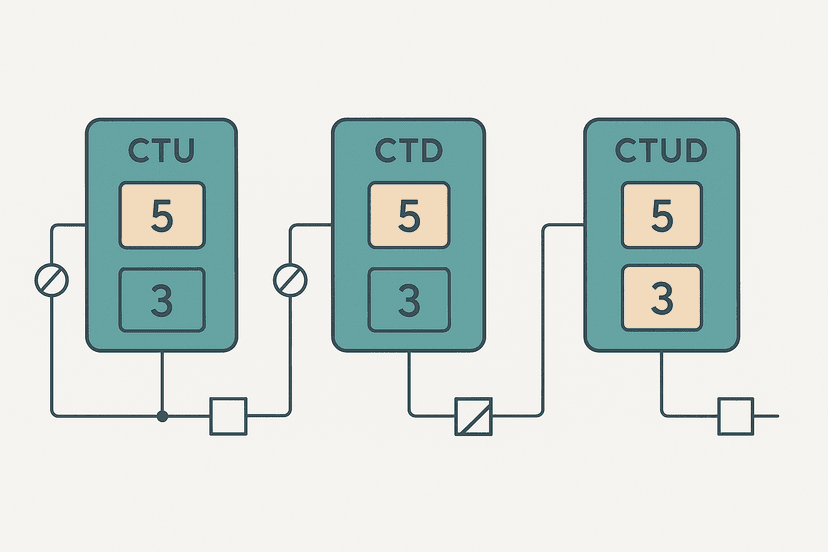
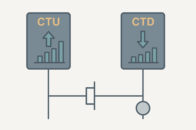
Now that PRE and ACC make sense, the next step is understanding when to use CTU versus CTD versus the bidirectional CTUD, and how to chain counters for multi-stage batch logic. The PLC counter instructions reference covers all three instruction types, and the CTU vs CTD comparison goes deeper on the differences. If you want to see counters used inside a full machine sequence, the bottle filling machine project is a solid worked example with counters, timers and interlocks all working together.
Frequently asked questions
What is the preset value in a PLC counter?
What is the accumulator in a PLC counter?
What happens when ACC reaches the preset value?
How do you reset a PLC counter accumulator to zero?
Can the accumulator go negative or overflow?
Can you pre-load the accumulator to a value other than zero?
Is the counter accumulator retentive across a power cycle?
What is the difference between PRE and ACC in a CTD counter?
Can I change the preset value while the counter is running?
Why does my done bit turn on immediately when I first download the program?
Now build it
You have just read about CTU and RES and CTD. Reading a rung and making one behave are different skills, and the second one is the job.
Batch Counter (CTU + RES)
Intermediateabout 15 minCount parts passing a sensor; after 4 parts the batch is done and a lamp turns on. A reset button starts the next batch. Counters count RUNG EDGES: a part sitting on the sensor counts once, not forever.
Build this rungFree, no signup, runs in your browser. See all 16 exercises.
Was this helpful?