Relay vs Transistor PLC Outputs: Full Comparison
You're speccing a PLC panel and the output module catalogue shows relay and transistor options at similar prices. Pick the wrong one and you'll either burn contacts in three months or find out on commissioning day that your stepper drive ignores the pulse signal completely. The choice matters more than most people think, and the datasheet rarely tells you the whole story.
What Is the Difference Between Relay and Transistor PLC Outputs?
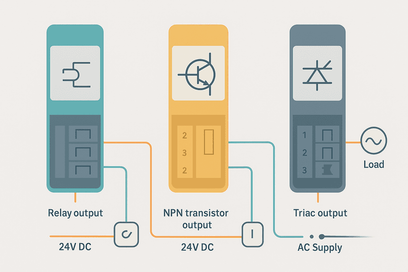
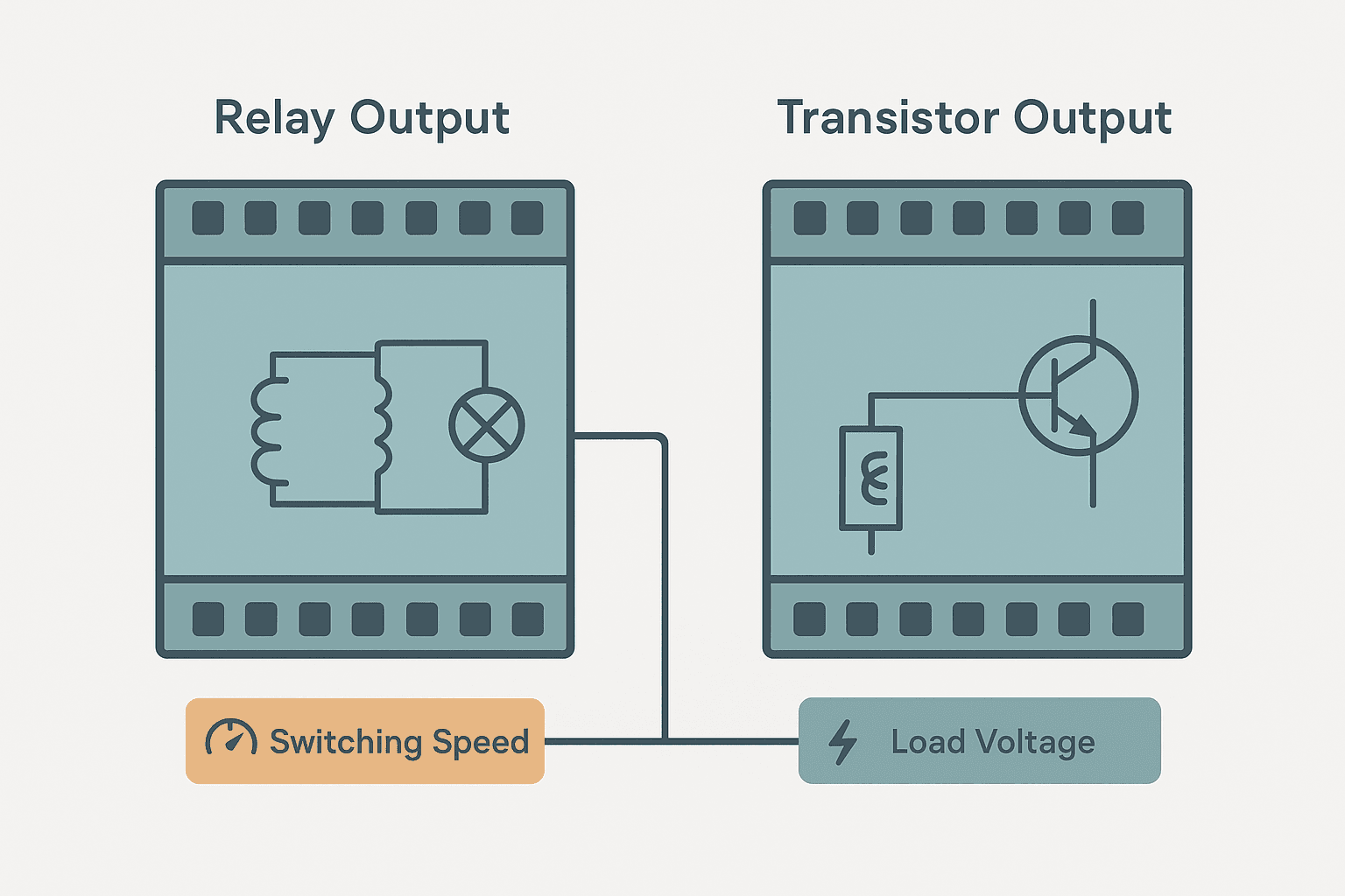
A relay output module switches each output channel using a small electromechanical relay inside the module. The relay contact is electrically isolated from the PLC backplane, can switch AC or DC, and handles resistive, inductive and lamp loads. A transistor output module switches using a bipolar transistor or MOSFET. It has no moving parts, switches in under 1 ms, handles DC only (typically 5 to 30 VDC), and can run for hundreds of millions of cycles without degradation. That 15 ms versus 0.1 ms speed gap is the single biggest practical difference between the two.
Side-by-Side Comparison
| Property | Relay Output | Transistor Output |
|---|---|---|
| Switching speed | 8 to 15 ms typical | 0.1 to 1 ms typical |
| Supported voltage | AC or DC (5 to 250 VAC/VDC typical) | DC only, 5 to 30 VDC typical |
| Isolation | Galvanic (contact isolation) | Optical (optocoupler) |
| Contact/cycle life | 1 to 10 million operations | Effectively unlimited |
| Inrush/inductive loads | Arc and wear contacts | Protected by internal clamp or needs external diode |
| Current per point | 1 to 2 A typical | 0.1 to 0.5 A typical |
When Relay Outputs Win
Relay outputs are the right call whenever you need to switch AC loads from the PLC directly. Pilot lights on 120 VAC panels, small AC contactors, 24 VAC solenoid valves, and legacy AC-powered devices all fall into this category. The galvanic isolation of a relay contact is also genuinely useful: the load circuit is completely separated from the PLC's DC commons, which simplifies grounding in panels that mix multiple voltage levels.
Relay outputs also handle higher per-point current, often 2 A per channel versus 0.5 A for a transistor point. That headroom matters when you're directly driving a contactor coil rated at 1.5 A without an interposing relay. And if you're wiring a panel with mixed 24 VDC and 120 VAC outputs, a relay output module is the only standard option that covers both from one module. For a deeper look at how relay contacts compare to contactor contacts in the wider panel context, see Relay vs Contactor: Wiring Differences Explained.
When Transistor Outputs Win
Any application with high switching frequency belongs to transistor outputs. If you're counting pulses, driving a stepper motor step/direction signal, controlling a proportional valve with PWM, or switching a 24 VDC solenoid that cycles more than a few times per minute, the transistor output is the correct choice. There are no contacts to arc, no bounce, and no mechanical fatigue.
High-speed pulse outputs for stepper drives typically need 10 kHz to 100 kHz. A relay physically cannot do that. Transistor outputs on purpose-built motion modules go up to 200 kHz or higher. For high-cycle 24 VDC solenoid outputs (pneumatic cylinders, proportional valves), transistor points will outlast the machine itself. When you're wiring those DC solenoids, the PLC Analog Output Wiring: 4-20 mA and 0-10 V article covers the analog side of the same wiring practice, and PLC Output Wiring: Relay, Transistor and Triac walks through the physical wiring for all three output types in detail.
NPN vs PNP Transistor Outputs
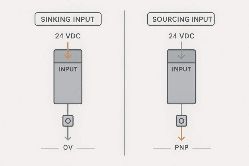
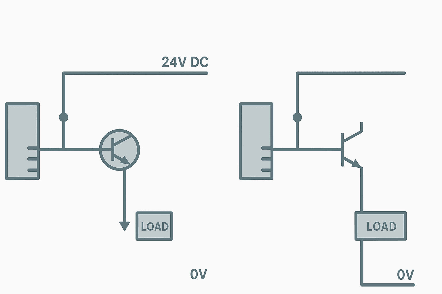
Transistor outputs come in two polarities. An NPN (sinking) output pulls the load terminal to 0 V when active. The load sits between the positive supply rail and the output terminal. A PNP (sourcing) output pushes the positive supply to the load terminal when active. In North American panels, PNP sourcing outputs are far more common. In Asian markets, NPN sinking is historically dominant. This mirrors the sensor polarity convention you'll see in Sinking vs Sourcing PLC I/O: Wiring It Right and NPN vs PNP Sensors: Wiring and PLC Connection.
Mixing NPN and PNP in the same panel without thinking it through causes nuisance faults. If your sensors are NPN and your outputs are PNP sourcing, your 0 V common references may not align cleanly. Get this sorted in the design phase, not on the floor.
Protecting Relay Contacts and Transistor Outputs
Inductive loads generate back-EMF spikes when the current is interrupted. For relay outputs, the spike causes arcing across the opening contact, which deposits carbon, erodes the contact surface, and accelerates wear. The fix is a snubber circuit (RC network) for AC loads or a flyback suppression diode for DC loads, wired directly across the load coil. This is cheap and takes ten minutes. Not doing it is a warranty claim waiting to happen.
For transistor outputs, most modern modules include internal transient voltage suppressors or zener clamp circuits, but they are sized for moderate spikes. A large solenoid or long cable run can still exceed the clamp rating. An external flyback diode across the load coil is always a safe addition. The diode needs to be rated for at least the supply voltage and the steady-state load current: a 1N4007 (1 A, 1000 V) covers most 24 VDC solenoid applications.
Current Capacity and Module Power Budgets
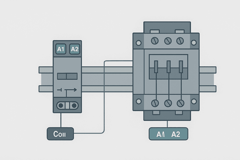
Relay modules typically allow 1 to 2 A per output point, but check the per-module (common) current rating too. A 16-point relay module might allow 2 A per point but only 8 A total across all points in a common group. Transistor modules are usually limited to 0.1 to 0.5 A per point with similar common limits. If you're driving a 24 VDC contactor coil that draws 1.2 A, a 0.5 A transistor output will not work. Either use a relay output or add an interposing relay.
This matters especially on compact PLCs where the output commons are shared across all points. Exceeding the common current limit can damage the module even if no individual point is overloaded. Always check both ratings. The 24 VDC Power Supply Sizing for Control Panels article covers the upstream supply side of this same calculation.
Triac Outputs: the Third Option
Some PLC modules offer triac outputs. A triac is a solid-state AC switch: faster than a relay, no contact wear, but AC only. Triac outputs are common on small European PLCs and on modules designed for AC lamp or AC solenoid control. They handle zero-crossing switching well, which reduces electrical noise. The downside is that triacs leak a small current when off, which can keep sensitive loads energized. They're not ideal for resistive heating elements where you need true zero current in the off state. If you're choosing between relay and triac for an AC load, triacs win on cycle life but lose on compatibility with certain load types.
Fault Diagnosis: Knowing Which Output Type You Have
When troubleshooting a stuck output, knowing the output type changes your diagnostic approach. For a relay output, you can hear a healthy relay click when the output bit is forced on. No click with the bit active usually means a blown fuse on the output common, a failed relay coil, or a missing supply voltage to the common terminal. For a transistor output, there's no audible indication. You measure voltage at the output terminal: should be near supply voltage (PNP) or near 0 V (NPN) when active, and floating or supply voltage when inactive. A transistor output that is always on usually means the transistor has failed short-circuit, often from an overload or a reversed supply connection. The PLC Output Faults: How to Diagnose Them Fast article has a full step-by-step for both output types.
One more gotcha: if a relay output tests fine at the terminals but the load doesn't respond, check the fuse on the output common. Most relay output modules use individual or grouped fuses that protect the common rail. A blown fuse kills all outputs in that group silently. See PLC I/O Fault Diagnosis with a Multimeter for the exact voltage and resistance checks.
Practical Selection Rules
- AC load at any voltage: relay output (or triac for high-cycle AC).
- DC load switching more than 10 to 20 times per minute: transistor output.
- Stepper or servo pulse/direction signals: transistor output only.
- High current DC load above 0.5 A: relay output or external contactor driven by transistor output.
- Mixed AC and DC in same panel: use separate relay and transistor modules, or relay output with snubbers for both.
- Safety outputs (e.g. STO, guard relay): check the safety relay or safety PLC datasheet; standard transistor outputs are not certified for safety functions without additional hardware. See Emergency Stop Circuit Wiring: Categories Explained.
- High-density panels on a tight budget: transistor outputs are often cheaper per point and smaller per module than relay equivalents.
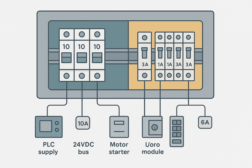
For the fusing and overcurrent protection side of this decision, Fuse vs Breaker Selection for Control Panels covers how to size protection for both relay and transistor output circuits. And if you're working through general output wiring practices, Control Panel Wire Routing and Segregation is worth a read before the panel goes together.
What to Read Next
If you want to go deeper on how outputs are wired physically, PLC Output Wiring: Relay, Transistor and Triac shows the full wiring diagrams for all three types with common and isolated configurations. To understand the sinking and sourcing conventions that govern transistor output polarity, Sinking vs Sourcing PLC I/O: Wiring It Right is the clearest breakdown on the site. And if you want to practice ladder logic that controls these outputs in context, the free interactive ladder editor lets you build and test output control rungs without any hardware.
Frequently asked questions
What is the main difference between relay and transistor PLC outputs?
Can a relay PLC output switch AC loads?
How fast can a transistor PLC output switch?
What loads can damage a relay output contact?
What is the difference between NPN and PNP transistor outputs?
Can I use a transistor output to control a 24 VAC solenoid?
How long do relay output contacts last in a PLC module?
Do I need a flyback diode on a transistor PLC output?
Which PLC output type is better for a stepper motor pulse signal?
Can relay and transistor outputs be mixed on the same PLC?
Learn this by building it
There is a PLC in this site. It runs a real scan engine, checks your logic against the same tests a working machine would fail, and needs no download and no account.
Open the exercisesFree, no signup, runs in your browser. See all 16 exercises.
Was this helpful?