What Is a SCADA System and How Does It Work?
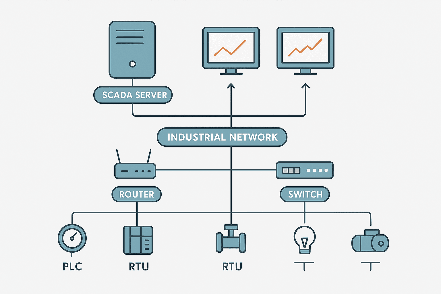
SCADA stands for Supervisory Control and Data Acquisition. Strip away the jargon and it is a software-based system that collects real-time data from field devices, displays it to operators, logs it historically, and lets those operators send commands back to the process. That is the full job description. Everything else is implementation detail.
The term gets thrown around loosely. You will hear people call a single touchscreen a SCADA system and also hear Fortune 500 utilities call a 200-server installation SCADA. Both are technically correct, which is why the term confuses newcomers. This post walks through what the components actually are, how they connect, and where SCADA ends and a PLC or HMI begins.
What SCADA Actually Stands For (and What Each Word Means)
- Supervisory: The system sits above the direct control layer. It supervises rather than executes millisecond-level control loops.
- Control: Operators can issue setpoint changes, open/close valves, start/stop pumps through the interface.
- And Data: The two functions are combined into one platform.
- Acquisition: The system polls or receives data from field devices continuously and stores it.
That supervisory distinction is the most important one. A PLC executes its scan cycle every 1 to 20 ms and closes control loops in real time. SCADA polls data every 1 to 5 seconds in a typical installation and sends operator commands that the PLC then acts on. SCADA is not doing the microsecond PID work. The PLC is.
The Five Core Components of a SCADA System
| Component | What It Does | Typical Hardware or Software |
|---|---|---|
| Field Devices | Measure and actuate: sensors, transmitters, valves, motor starters | Pressure transmitters, flow meters, VFDs, solenoid valves |
| PLCs and RTUs | Execute local control, buffer data, report to SCADA | Siemens S7-1200, Allen-Bradley CompactLogix, Schneider Modicon, dedicated RTUs |
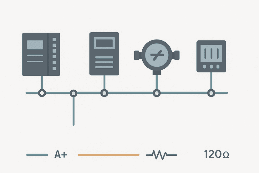
| Communications Network | Carries tag data between field level and SCADA server | Ethernet/IP, PROFINET, Modbus TCP, DNP3, cellular, radio |
| SCADA Server | Polls PLCs, stores historian data, runs alarming logic, serves clients | Wonderware AVEVA, Ignition, WinCC, FactoryTalk View SE, ClearSCADA |
| Operator Workstations / HMIs | Display process graphics, trends, alarms; accept operator commands | PC-based thin clients, dedicated panel PCs, web browsers (modern platforms) |
PLCs vs RTUs: What Is the Difference?
RTU stands for Remote Terminal Unit. Historically RTUs were used in oil and gas pipelines and power distribution where the field device was kilometres from the control room, battery-backed, and communicating over slow serial links or radio. PLCs came from factory automation and assumed reliable power and fast networks. Today the lines have blurred significantly. A modern Schneider Electric SCADAPack RTU runs IEC 61131-3 logic just like a PLC. An Allen-Bradley ControlLogix running DNP3 over cellular does what an RTU used to do. In practice, the word RTU now mostly signals a remote, often battery-backed unit in utilities or oil and gas. On a factory floor you will almost always see PLCs.
How a SCADA System Works: Data Flow Step by Step
Here is what happens from sensor to screen in a typical installation:
- A pressure transmitter outputs a 4-20 mA signal proportional to tank pressure.
- The PLC analog input module converts that signal to a raw integer (typically 0-27648 on a Siemens S7, or 0-32767 on a Rockwell system).
- The PLC scales that raw count to engineering units (bar or PSI) inside its program.
- The SCADA server polls the PLC over Modbus TCP or OPC UA, reading the scaled pressure tag every second.
- The historian database logs the value with a timestamp.
- The operator workstation displays the current value on a process graphic, plots a trend, and checks it against high/low alarm limits configured in the SCADA software.
- If the operator changes a setpoint on the graphic, the SCADA server writes that value back to a PLC register. The PLC acts on it in its next scan.
SCADA vs HMI vs PLC: Where Each One Stops
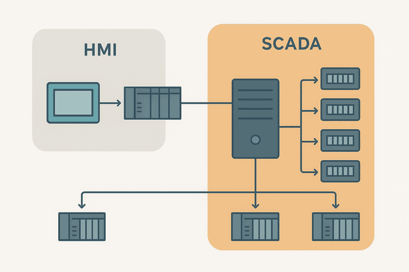
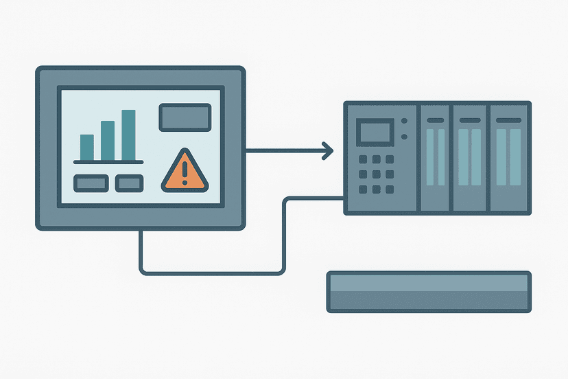
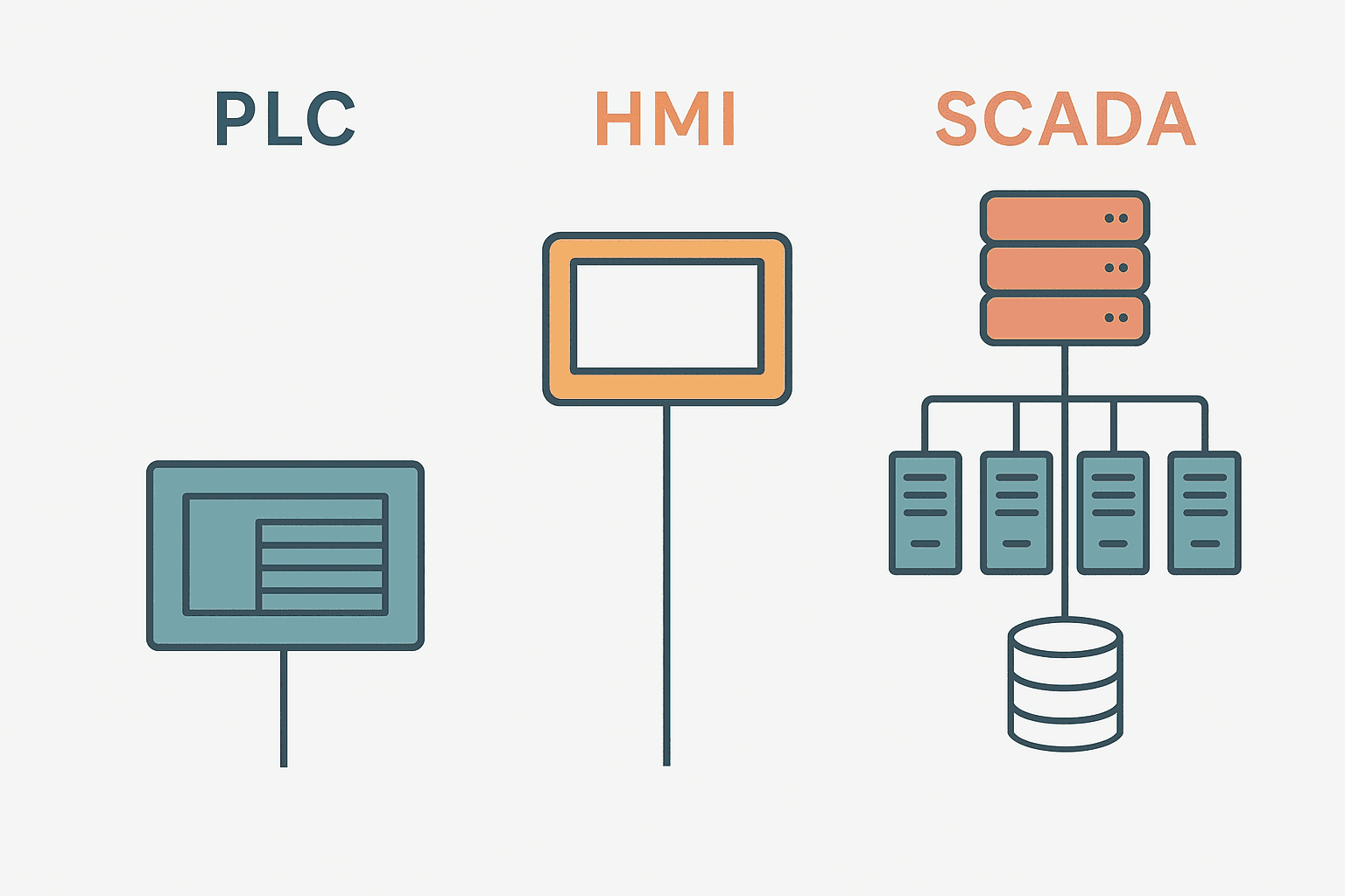
This is the question that causes the most confusion. The short version: a PLC controls, an HMI visualises a single machine or cell, and SCADA supervises multiple PLCs across a site or geography. If you want the full breakdown with real examples, the post SCADA vs HMI: What Actually Differs and Why It Matters covers that comparison in detail.
The practical test: if your system has one PLC and one panel PC on the same machine, that is an HMI. If your system has 12 PLCs across a facility, a centralised server logging everything to a historian, and operators in a control room watching the whole plant, that is SCADA. The boundary is architectural, not about software brand.
Real-World SCADA Examples by Industry
| Industry | What SCADA Monitors and Controls | Typical Scale |
|---|---|---|
| Water and Wastewater | Pump stations, tank levels, chlorine dosing, flow across a distribution network | Dozens to hundreds of RTU/PLC sites over a city |
| Oil and Gas Pipeline | Compressor stations, pressure and flow along a pipeline, pig launcher valves | Sites separated by 50 to 200 km, often on cellular or radio |
| Power Distribution | Substation breaker status, transformer load, fault detection, automatic reclosing | Regional grid management, DNP3 protocol common |
| Manufacturing | Production counts, reject rates, OEE across multiple lines or factories | Single site with 5 to 50 PLCs on Ethernet |
| Building Automation | HVAC setpoints, chiller efficiency, lighting zones across a campus | BACnet or Modbus, sometimes called BMS rather than SCADA |
The Communications Protocols SCADA Relies On
SCADA systems are protocol-agnostic by design. The server needs a driver or OPC UA connection to talk to whatever PLCs or RTUs are in the field. In practice you will see:
- Modbus TCP on legacy and low-cost installations. Simple, well-supported, no security by default. See our deep-dive on Modbus RTU for how the underlying framing works.
- OPC UA on modern factory SCADA. Vendor-neutral, encrypted, supports complex data types and historical access natively. The preferred choice for new builds.
- DNP3 in utilities and water. Designed for unreliable WAN links, with built-in integrity checks and unsolicited reporting so the RTU can push alarms without being polled.
- PROFINET / EtherNet/IP where the SCADA server sits on the same plant network as Siemens or Rockwell PLCs and uses the vendor's native OPC UA or DCOM driver.
- Cellular (4G/5G) and radio for geographically distributed sites where running fibre is impractical.
SCADA Software: On-Premise vs Cloud vs Hybrid
Historically SCADA ran on dedicated Windows servers in the control room. That is still common in utilities and regulated industries where change control is slow. But the newer platforms have shifted the architecture significantly:
- Inductive Automation Ignition runs as a Java web server, clients connect via browser. No per-client licences. Easy to scale. Very popular in food, pharma, and discrete manufacturing.
- AVEVA System Platform (Wonderware) is the enterprise tier with redundancy, distributed historians and integration into MES and ERP layers.
- Siemens WinCC integrates tightly with TIA Portal and S7 PLCs. Good choice when the whole plant is Siemens.
- Rockwell FactoryTalk View SE is the natural pairing for Studio 5000 and ControlLogix sites.
- Cloud SCADA (AWS IoT, Azure IoT, Ignition Edge + MQTT) pushes data to cloud historians for multi-site dashboards, predictive analytics, and remote monitoring. The PLC still runs locally. Only data travels to the cloud.
What the SCADA Historian Actually Does
The historian is one of the most underrated parts of a SCADA system. It is a time-series database optimised for storing thousands of tags at high sample rates without the overhead of a relational database. OSIsoft PI (now AVEVA PI), the Ignition Tag Historian, and WinCC's Process Historian are common examples. You query the historian to build trend charts, generate compliance reports, calculate OEE, or do post-incident analysis after a trip.
A well-configured historian stores data at 1 second resolution or better for critical process variables. A poorly configured one stores data every 30 seconds or only on change with a deadband set too wide, and then the trend charts look like staircase functions rather than smooth curves. Get the deadband and sample rate settings right during commissioning. Fixing them retroactively means you have gaps in historical data that you can never recover.
Alarm Management in SCADA: The Part Most Projects Get Wrong
SCADA alarm management is where most projects create problems for themselves. The classic failure mode: an engineer configures a high alarm and a high-high alarm on every single analog tag during commissioning because it is quick to do. Six months into operation the operators are seeing 500 alarms per day, most of them chattering nuisance alarms, and they start ignoring the annunciator. That is how incidents happen.
The ISA-18.2 standard gives you a framework for doing this properly: define alarm philosophy first, rationalise each alarm to confirm it requires operator action, set deadbands to prevent chattering, and target no more than 1 to 2 alarms per operator per 10 minutes during normal operation. The SCADA software supports most of this. The discipline to actually implement it is the hard part.
Quick Summary: What SCADA Is and Is Not
- SCADA is supervisory software that collects, displays, logs and alarms on data from multiple PLCs or RTUs.
- SCADA is not doing real-time millisecond control. The PLC does that.
- SCADA is not just an HMI. It spans multiple devices, sites, and often geographies.
- SCADA can write setpoints and commands back to PLCs, but the PLC executes them.
- SCADA does include a historian for trend data and compliance reporting.
- SCADA does not replace functional safety systems. E-stops and safety PLCs operate independently.
Frequently asked questions
What does SCADA stand for?
What is the difference between SCADA and a PLC?
What protocols does SCADA use to communicate with PLCs?
What is a SCADA historian and why does it matter?
Can SCADA systems be hacked, and how do you protect them?
What is the difference between SCADA and DCS?
Learn this by building it
There is a PLC in this site. It runs a real scan engine, checks your logic against the same tests a working machine would fail, and needs no download and no account.
Open the exercisesFree, no signup, runs in your browser. See all 16 exercises.
Was this helpful?