SCADA System Architecture: Layers, RTUs and the Master Station
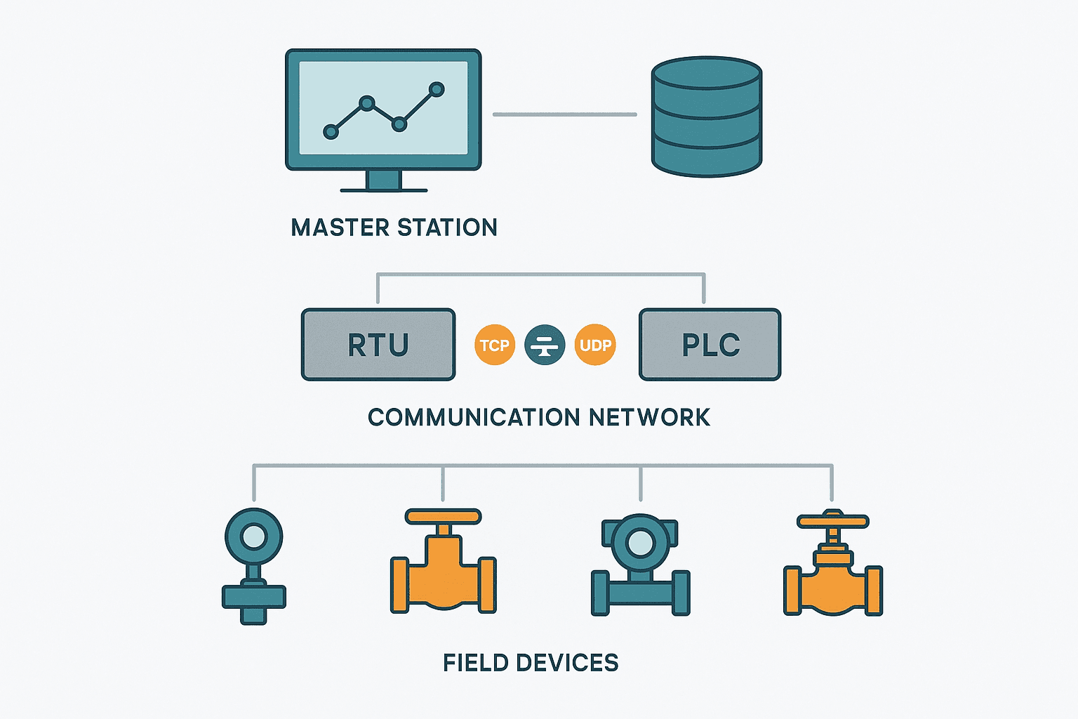
A SCADA system is not a single box. It's a hierarchy of hardware and software that spans kilometres, sometimes continents, and every layer has a specific job. If you've ever tried to troubleshoot a communication gap between a remote pump station and a control centre without understanding how the architecture is supposed to work, you know exactly why this matters.
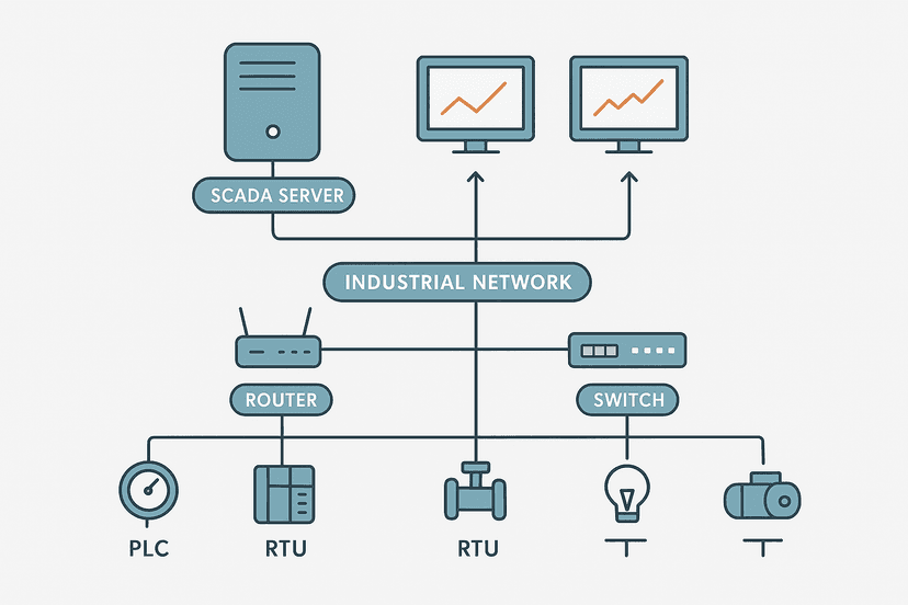
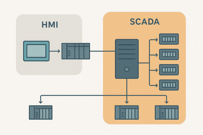
This post breaks down the classic three-layer SCADA architecture, explains what an RTU actually does versus a PLC, and describes what the master station (MTU) is responsible for. We'll also cover how modern Ethernet and IP networks changed the traditional model, and where the historian and HMI fit into the picture. If you want the high-level comparison of SCADA and HMI first, SCADA vs HMI: What Actually Differs and Why It Matters is a good primer.
The Three-Layer SCADA Architecture
Nearly every SCADA textbook and vendor white paper organises a SCADA system into three functional layers. The naming varies slightly, but the structure is consistent across water utilities, oil and gas pipelines, power distribution, and rail systems.
| Layer | Common Name | Typical Hardware | Primary Job |
|---|---|---|---|
| 1 (bottom) | Field Layer | Sensors, transmitters, actuators, RTUs, PLCs | Measure and control physical processes |
| 2 (middle) | Communication Layer | Serial networks, IP WAN, fibre, cellular modems, radio | Move data reliably between field and control centre |
| 3 (top) | Supervisory Layer | MTU/master station, historian, HMI workstations, SCADA server | Aggregate data, store history, display to operators, run supervisory logic |
Layer 1 generates the data. Layer 2 carries it. Layer 3 makes sense of it. Every design decision in a SCADA project ultimately comes down to which devices live in which layer and how you get data reliably from Layer 1 to Layer 3 across whatever distance and network topology you're dealing with.
Layer 1: Field Devices and Remote Outstations
At the bottom of the stack you have the physical world: pressure transmitters outputting 4-20 mA, flow meters pulsing a digital signal, motorised valves with position feedback, and variable-speed pumps reporting run status. These signals land on an RTU or a PLC at the remote site.
RTU vs PLC: Not the Same Thing
This is the question that trips people up the most. An RTU (Remote Terminal Unit) was purpose-built for SCADA from the beginning. Its design priorities are low power consumption, hardened operation in outdoor or uncontrolled environments, reliable long-distance communications, and the ability to operate autonomously for extended periods when the communication link goes down. Classic RTUs from Bristol Babcock, Emerson ROC, or ABB Totalflow have on-board data logging and can buffer thousands of records so nothing is lost during a comms outage.
A PLC is primarily a real-time control device. It was designed for machine control with fast scan cycles (1-10 ms is common), rich instruction sets, and tight integration with motion and safety systems. You can absolutely use a PLC as an RTU substitute, and on many modern sites that's exactly what happens. A CompactLogix or S7-1200 on a water booster station does the job fine. But a true RTU tends to win when: you need sub-milliwatt sleep modes for solar-powered sites, the comms link is a 1200-baud radio channel, or you need IEC 61968/IEC 60870-5-101/104 protocol support natively.
What an RTU Actually Does Locally
- Scans analog inputs (typically 4-20 mA, 0-5 VDC, thermocouple) and digital I/O at configurable rates
- Applies engineering unit scaling and deadband filtering so only meaningful changes are reported
- Executes simple local control logic (PID loops, setpoint alarming, override logic)
- Buffers data with timestamps when comms to the master station are lost
- Responds to polls from the master station or initiates unsolicited reports depending on the protocol
- Manages its own watchdog and safe-state outputs if power or comms are lost
That deadband filtering point is worth calling out. A pressure transmitter on a 1200-baud radio link can't send every sample to the master station. The RTU only reports a new value when the reading has changed by more than the configured deadband, say 0.5% of span. This keeps the channel from being saturated while still giving operators meaningful data.
Layer 2: The Communication Network
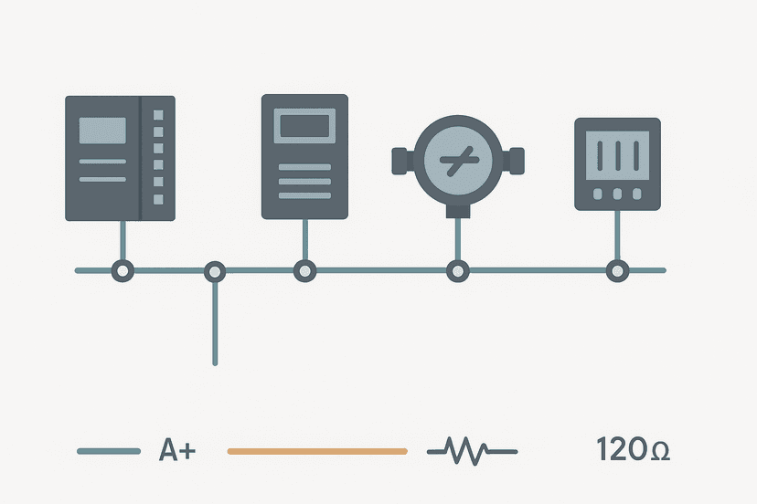
This layer is where old-school SCADA architecture looks very different from modern systems. Historically, the communication layer was serial: RS-232 or RS-485, running Modbus RTU or DNP3 at 9600 to 19200 baud over leased telephone lines, radio modems, or microwave links. Bandwidth was scarce. Latency was high. Everything was optimised around polling small data packets.
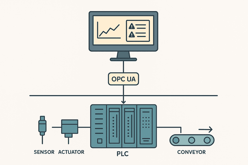
Today most new SCADA communication layers are IP-based: fibre Ethernet, 4G/LTE cellular, or private licensed radio with IP modems. Protocols like DNP3 over TCP/IP, IEC 60870-5-104, and OPC UA are now the norm. That shift has blurred some of the old boundaries between layers because you can now stream large amounts of data cheaply. But the architecture concepts still hold.
| Protocol | Physical Medium | Typical Use Case | Notes |
|---|---|---|---|
| Modbus RTU | RS-485 | Short-range RTU to local PLC or gateway | Still very common on older sites |
| DNP3 (serial) | RS-232/485 or radio | Utility SCADA, water, oil and gas | Built-in data integrity and time-stamping |
| DNP3 over TCP | Ethernet/IP WAN | Modern utility SCADA over IP networks | Same data model as serial DNP3 |
| IEC 60870-5-104 | Ethernet/IP WAN | Power utility SCADA in Europe and Asia | IEC standard equivalent to DNP3 in many respects |
| OPC UA | Ethernet | Plant-level SCADA to historian, MES | Rich data model, security built in |
| 4G/LTE cellular | Cellular WAN | Remote sites with no fibre or radio | VPN essential; latency 50-200 ms typical |
Layer 3: The Master Station (MTU)
The Master Terminal Unit, or master station, is the brain of the SCADA system. It sits at the control centre and is responsible for everything the operators actually see and interact with. On a small water district system it might be a single industrial PC running Ignition or Wonderware. On a large transmission pipeline it could be a redundant pair of servers with separate historian, alarm server, and reporting nodes.
What the Master Station Does
- Polls all RTUs and PLCs on a defined schedule, or receives unsolicited reports, and assembles a real-time database of all field values
- Applies system-wide alarming rules: high/low limits, rate-of-change alarms, comms loss detection
- Presents the process to operators via graphical mimic displays (the HMI component of SCADA)
- Accepts operator commands (open valve, start pump, change setpoint) and sends them down to the appropriate RTU or PLC
- Logs every value, alarm, and operator action to the historian with accurate timestamps
- Runs supervisory control logic: things like automatic load balancing across reservoirs, or demand-based pump scheduling, that span multiple remote sites
- Generates scheduled and on-demand reports for operations and management
That last point about supervisory logic is worth dwelling on. The master station can make control decisions that no single RTU can make alone because it sees the whole system. A water network master station knows the level in every reservoir, the flow on every trunk main, and the status of every pump station simultaneously. It can calculate that Pump Station 7 needs to start in 20 minutes to prevent Reservoir 3 from dropping below a minimum level, and it can send that start command automatically. That's supervisory control, not just monitoring.
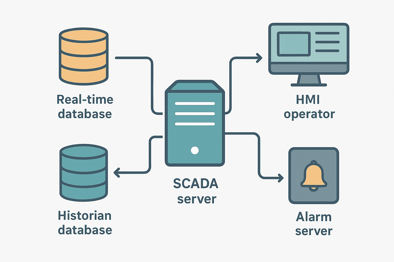
The Historian: Why It Deserves Its Own Mention
A process historian is a time-series database optimised for storing millions of tagged values per second with high compression. OSIsoft PI (now AVEVA PI), Ignition's built-in Tag Historian, and Wonderware Historian are the names you'll see most often. The historian is not just a log file. It's a queryable database that lets you pull up the exact tank level curve from 18 months ago, correlate it with a pump run-time trend, and figure out why you had a pressure event. Without a historian, SCADA is just a real-time display. With one, it becomes an operational intelligence tool.
Redundancy in SCADA Architecture
Any SCADA system controlling critical infrastructure needs redundancy at multiple levels. Here's how it's typically implemented:
- Master station redundancy: A hot-standby server pair where the secondary mirrors the primary in real time and takes over in under 5 seconds on failure. Ignition, Wonderware, and Citect all support this natively.
- Communication path redundancy: Dual communication paths to critical RTUs, for example primary fibre and secondary 4G cellular, with automatic failover.
- RTU power redundancy: Uninterruptible power supply and, at solar-powered remote sites, battery backup sized for 3-5 days of autonomy.
- RTU comms redundancy: Some RTUs support dual network cards or dual serial ports so if one comms module fails, the other takes over without a restart.
- Historian redundancy: A secondary historian node replicating from the primary, sometimes at a geographically separate data centre.
How Modern IP Networks Changed the Model
The traditional SCADA architecture assumed a serial communication layer with high latency and low bandwidth. RTUs were designed to work with that constraint. Modern IP WAN connectivity has flipped those assumptions. You can now stream 100 ms analog samples from 500 remote sites over a private MPLS network or a managed cellular connection without saturating the link.
This has led to a few architectural shifts. First, the line between RTU and PLC has blurred further because PLCs can now run DNP3 or IEC 60870-5-104 stacks via add-on modules or software. Second, the push to OPC UA as the universal interface between field systems and the supervisory layer means some sites now skip the traditional polling model entirely and run a subscribe-on-change model that is closer to how industrial Ethernet works at the plant level. Third, edge computing is creeping into Layer 1: devices like Siemens SINEMA Remote Connect, Tosibox, or Cisco IR1101 industrial routers do more than just pass data through; they can run local analytics or protocol translation.
The architecture layers are still valid. The hardware that implements them has just got more capable. If you want to understand how the PLC and SCADA layers interact at the plant level specifically, SCADA vs PLC: How They Work Together on the Plant Floor covers that relationship in detail.
SCADA System Architecture: A Quick Reference
| Component | Where It Lives | Key Responsibility | Fails Gracefully? |
|---|---|---|---|
| Field sensor / transmitter | Layer 1, field | Convert physical variable to electrical signal | RTU holds last-known value |
| RTU / remote PLC | Layer 1, field | I/O scan, local control, data buffering, comms | Runs autonomously; buffers data |
| Communication network | Layer 2 | Move data between field and master station | Redundant paths recommended |
| SCADA server / MTU | Layer 3, control centre | Poll, aggregate, alarm, supervisory logic | Hot-standby redundancy |
| HMI workstation | Layer 3, control centre | Operator display and command entry | Multiple workstations typical |
| Historian | Layer 3, control centre | Time-series data storage and retrieval | Redundant historian node |
Common Design Mistakes to Avoid
- No deadband on analog inputs over slow links. Sending every 4-20 mA sample at 100 ms over a 9600-baud radio link will saturate the channel within seconds. Configure deadbands. 0.5-1.0% of span is a reasonable starting point.
- Single comms path to critical sites. One fibre cut or one cellular outage and you're blind. Budget for a secondary path on any site that has a safety or regulatory reporting obligation.
- Historian on the same machine as the SCADA server. When the SCADA server needs a restart, you lose historian logging too. Separate them, even on a small system.
- No UPS on the master station. A power blip during an alarm event is the worst time to lose your SCADA server. 30 minutes of UPS runtime is the minimum; 2 hours is better.
- Flat network between SCADA and corporate IT. The SCADA network should be firewalled from the corporate LAN. A shared network means a ransomware event in the office can reach your control system.
Frequently asked questions
What is the difference between an RTU and a PLC in SCADA?
What does the SCADA master station (MTU) actually do?
How many layers does a SCADA system have?
What protocols are used in SCADA communication?
What is a SCADA historian and why is it important?
How is SCADA architecture different from a standard PLC and HMI setup?
Learn this by building it
There is a PLC in this site. It runs a real scan engine, checks your logic against the same tests a working machine would fail, and needs no download and no account.
Open the exercisesFree, no signup, runs in your browser. See all 16 exercises.
Was this helpful?