SCADA Control System Basics for Automation Engineers
If you've spent most of your career writing PLC logic, SCADA can feel like someone else's problem. Until the commissioning week when the project manager hands you a laptop, points at an Ignition or iFIX project, and says 'make it talk to your PLCs'. Suddenly it's very much your problem. This post covers what SCADA actually is at a technical level, how the pieces connect, and where the real gotchas live, from the field device all the way to the historian.
What a SCADA Control System Actually Does
SCADA stands for Supervisory Control and Data Acquisition. The name describes the job precisely. It supervises: it doesn't replace PLC logic, it monitors it. It acquires data: polling registers, timestamps them, and stores them. And it provides control: operators can send setpoints or commands down through it to the field devices below.
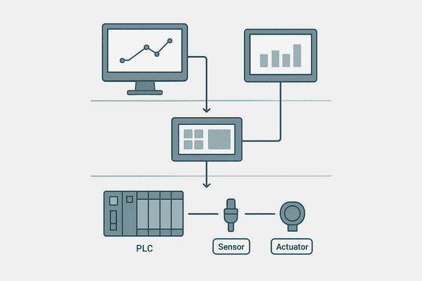
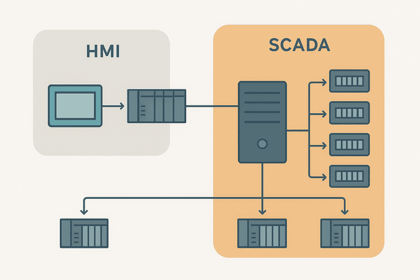
The key thing to internalize is that SCADA sits above the PLC, not instead of it. The PLC still runs the machine. The SCADA server is reading the PLC's memory and presenting it. If the SCADA server crashes at 2 a.m., your production line keeps running. If the PLC crashes, it stops. That distinction matters when you're arguing about where safety-critical logic belongs.
The Four Layers of a SCADA Control System
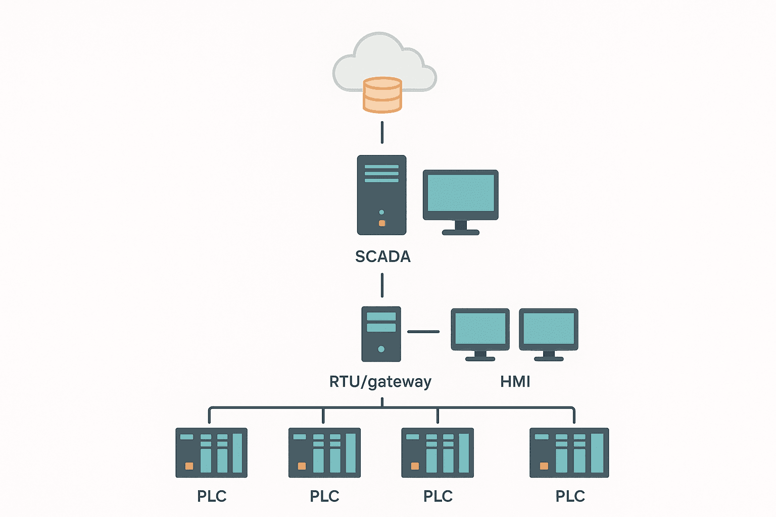
Every SCADA system, whether it's a small water treatment plant with one server or a 400-site utility with a redundant control centre, follows the same basic hierarchy. The layers just scale.
| Layer | Devices / Software | What It Does |
|---|---|---|
| Field (Level 0) | Sensors, actuators, drives, valves | Physically measures and moves things |
| Control (Level 1) | PLCs, RTUs, PACs, safety controllers | Runs closed-loop and sequence logic in real time |
| Supervisory (Level 2) | SCADA server, OPC UA server, historian | Collects data, presents it, allows operator commands |
| Enterprise (Level 3/4) | MES, ERP, data lakes, cloud analytics | Business-level reporting, scheduling, KPIs |
Most of what automation engineers build lives in layers 0 through 2. Level 3 is where the IT department starts appearing in your project meetings. The boundary between level 2 and level 3 is also where the Purdue Model (ISA/IEC 62443) draws its first serious security zone boundary. Worth knowing before you let someone plug a historian directly into your control network.
SCADA Core Components: What Each Piece Does
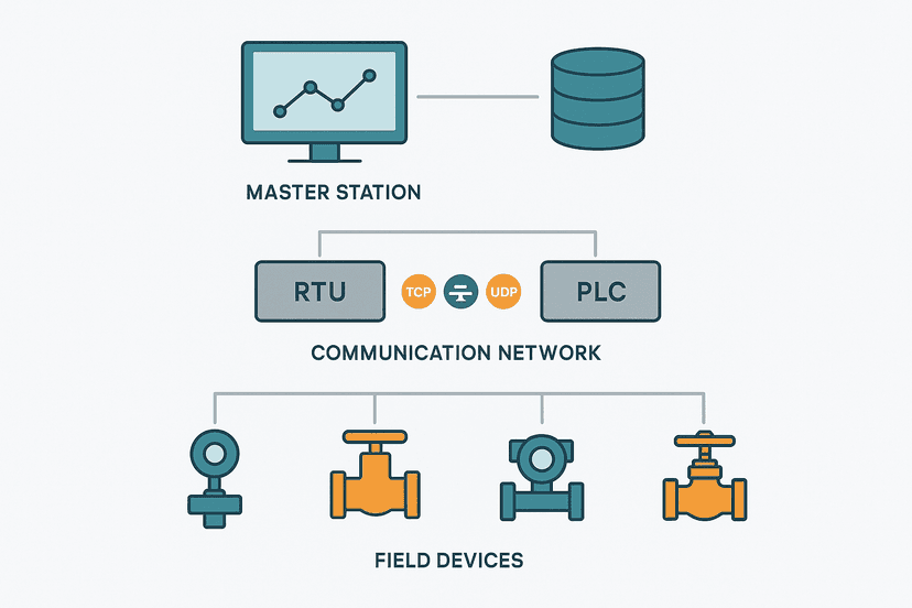
The SCADA Server (Master Station)
This is the brain. The SCADA server runs the driver software that polls PLCs, applies tag scaling, evaluates alarm conditions, writes to the historian, and serves live data to operator clients. On small sites this is one physical machine. On larger sites you'll see a redundant pair: primary and hot-standby, with automatic failover.
Popular SCADA platforms you'll encounter in the field: Ignition (Inductive Automation, cross-platform, uses OPC UA and JDBC natively), Wonderware/AVEVA System Platform (widely used in process industries, has its own object model), iFIX (GE/Proficy, strong in pharma and food), WinCC (Siemens, integrates tightly with TIA Portal and S7), FactoryTalk View SE (Rockwell, pairs with Studio 5000), and Citect (AVEVA, big in Australian mining). Each has its own tag database structure and driver ecosystem, but the underlying principles are identical.
RTUs and Remote Stations
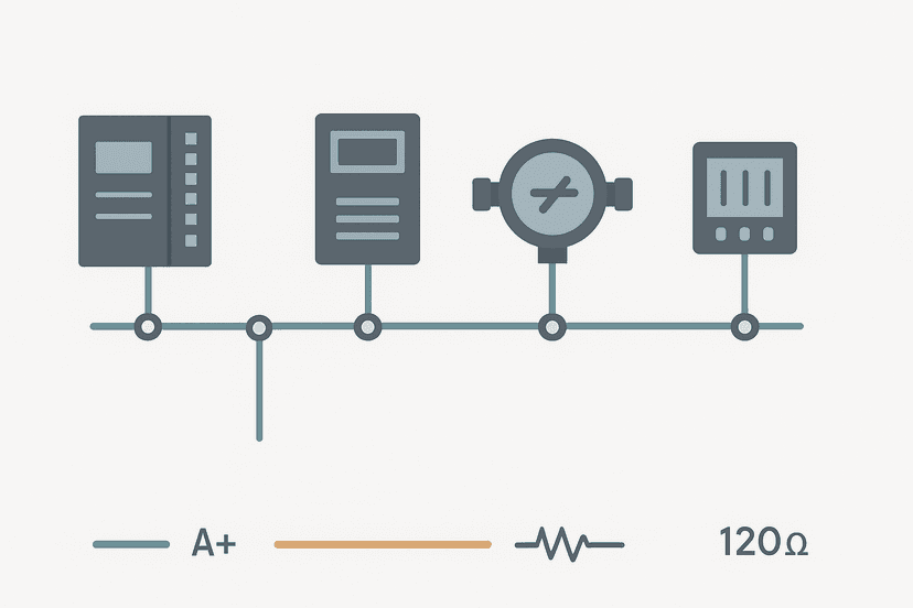
In geographically distributed systems like pipelines, water networks, or substations, you can't run EtherNet/IP or PROFINET hundreds of kilometres. That's where RTUs (Remote Terminal Units) come in. An RTU sits at the remote site, connects locally to sensors and actuators, and communicates back to the SCADA master over WAN links: serial radio, cellular 4G/5G, or satellite. Protocols used at this layer include DNP3, IEC 60870-5-101/104, and Modbus RTU over radio. Modbus RTU Protocol Explained covers the framing and timing if you need to go deeper on that one.
The Historian
The historian is a time-series database that stores tag values at high resolution, often every 1 second or faster for critical process variables. OSIsoft PI (now AVEVA PI) is the most common in process industries. Ignition has its own historian module. WinCC uses its own process historian. The historian is what makes trend analysis, SPC, and energy reporting possible. Without it, your SCADA is just a fancy live dashboard that loses all its data on reboot.
Operator Workstations and Thin Clients
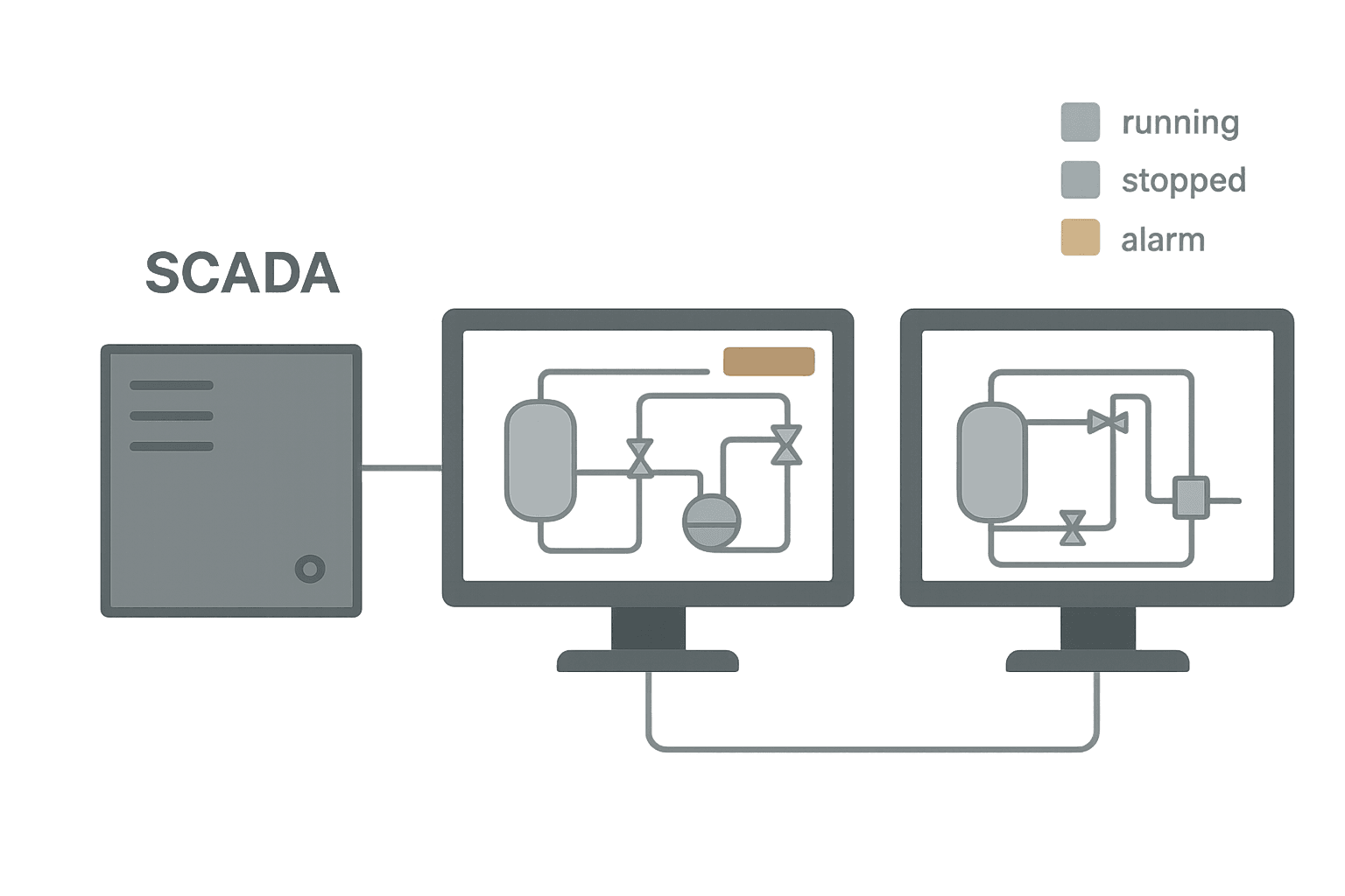
Operators interact with SCADA through graphical displays called mimics or faceplates. These show live process values, equipment status, and alarm states. Older systems ran thick clients: full SCADA application installed on every operator PC. Modern systems like Ignition use a web-based thin client approach, where the operator just needs a browser. This simplifies deployment significantly but introduces different security considerations.
How SCADA Talks to PLCs: Protocols and Drivers
This is where the PLC engineer needs to pay attention. SCADA doesn't have magic access to your PLC memory. It uses a driver that speaks the PLC's native protocol and reads specific registers or tags. Getting this configuration right is often the slowest part of commissioning.
| PLC Platform | Native Protocol | Typical SCADA Driver |
|---|---|---|
| Siemens S7-300/400/1200/1500 | S7 (ISO-TSAP) or OPC UA | Simatic NET, OPC UA client |
| Rockwell Logix (ControlLogix, CompactLogix) | EtherNet/IP (CIP) | RSLinx OPC, FactoryTalk Linx, Ignition Allen-Bradley driver |
| Modbus-compatible devices | Modbus TCP or RTU | Generic Modbus driver in most SCADA platforms |
| Mitsubishi MELSEC Q/iQ-R | SLMP or MC Protocol | Mitsubishi MC Protocol driver |
| Omron NJ/NX (Sysmac) | EtherNet/IP or OPC UA | EtherNet/IP or OPC UA client |
| Beckhoff TwinCAT | ADS (Automation Device Specification) or OPC UA | TwinCAT ADS driver, OPC UA client |
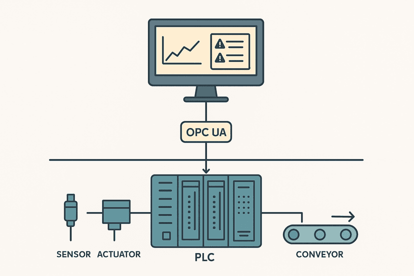
OPC UA is becoming the de facto standard for PLC-to-SCADA communication on new projects. It's vendor-neutral, supports structured data types, handles security with certificates and encryption, and maps cleanly to SCADA tag databases. If you're specifying a new system and your PLC supports OPC UA (S7-1500, NJ/NX, TwinCAT, CompactLogix with an OPC UA module all do), use it. You'll spend less time fighting driver licensing and more time doing useful work.
Tag Databases: The Backbone of Every SCADA Project
Every piece of data in a SCADA system is represented as a tag. A tag is a named variable with a data type, a source address (pointing to a PLC register or OPC UA node), engineering unit scaling, alarm limits, and historian settings. A 500-pump water treatment plant might have 15,000 to 50,000 tags. Getting the tag database right is genuinely tedious, but it determines how maintainable the system is for the next 20 years.
- Use a consistent naming convention from day one. ISA-5.1 instrument tag naming (P-101, TI-204) maps cleanly to SCADA tag names when you stick to it.
- Include engineering units in the tag definition, not just in the display. A raw integer from a 4-20 mA input means nothing without the scaling applied at the tag level.
- Set alarm deadbands on every analog tag. Without a deadband, a signal sitting right on the alarm threshold will generate hundreds of alarm events per minute.
- Separate read tags from write tags in your driver configuration. Polling a tag for display is different from writing a setpoint to the PLC. Mixing them up causes unexpected PLC writes.
- Document the PLC address or OPC UA node ID for every tag. When the PLC program is updated and addresses shift, you'll need this to find what broke.
SCADA Alarm Management: Where Most Systems Fail
Alarm flooding is the single most common SCADA problem in real plants. I've seen systems where an operator faces 400 alarms in the first 10 minutes of a process upset, most of them consequence alarms from the same root cause. The operator can't process them fast enough, acknowledges them in bulk, and misses the one that actually matters.
EEMUA 191 and ISA-18.2 give you the benchmark: a well-managed system should average no more than 1 alarm per 10 minutes per operator during normal operation, with a maximum of 10 alarms per minute during an upset. If your system is delivering 50 alarms per minute, you don't have an alarm system, you have noise.
- Assign priority (critical, high, medium, low) to every alarm and set display filters accordingly.
- Suppress consequence alarms: if the feed pump trips, the downstream level alarm should be suppressed automatically until the pump is restored.
- Use shelving for alarms on equipment that is known to be out of service. Don't delete them, just defer them with a timestamp and a reason.
- Review the alarm rationalization document with operations before go-live. The alarm limits you calculated from process engineering may not match what the operators actually need.
SCADA Security: The Part Nobody Wants to Budget For
SCADA systems used to run on proprietary hardware and serial links. Physical isolation was the security model. That era is over. Modern SCADA runs on Windows servers, uses Ethernet, and often has remote access for vendor support or cloud analytics. That connectivity is also an attack surface.
- Segment the control network from the corporate network with a DMZ and a firewall, not just a VLAN. IEC 62443 Zone and Conduit model is the reference.
- Never put SCADA servers on the same subnet as PLCs without a firewall or data diode between them and the corporate network.
- Disable unused services on SCADA servers: no web browsing, no email, no remote desktop from outside the DMZ without MFA.
- Keep SCADA software and OS patches current. Yes, this means planned downtime windows. Schedule them.
- Log all remote access sessions. Vendor VPN access should be time-limited and audited.
Redundancy: What to Make Redundant and What's Overkill
SCADA redundancy is about availability, not safety. The control system (PLC) must keep running regardless. SCADA redundancy means you don't lose visibility or historical data if a server fails.
| Component | Typical Redundancy Approach | Notes |
|---|---|---|
| SCADA Server | Hot-standby pair with automatic failover | Most enterprise SCADA platforms include this natively |
| Network (control LAN) | Dual ring or star with redundant switches | PROFINET MRP or EtherNet/IP DLR for ring topologies |
| Historian | Mirrored database or replicated to secondary site | Critical for regulatory compliance in pharma/food |
| Operator workstations | Multiple clients, any can take control | Thin clients make this easy; thick clients require licensing |
| WAN link to remote RTUs | Dual path: fibre primary, cellular backup | DNP3 handles link failover gracefully |
On a small plant with one building and a local SCADA server, you probably don't need a hot-standby server. A good backup and a 30-minute restore procedure is often sufficient and a lot cheaper. Save the redundancy budget for the communication paths to remote sites, where a link failure means you genuinely lose visibility of a remote station.
Getting SCADA Commissioned: Practical Steps
Here's the sequence that actually works in the field, based on systems from 50 tags to 50,000.
- Lock down the tag list and naming convention before any SCADA configuration starts. Changes after the fact are expensive.
- Build the PLC program with descriptive tag names that match the SCADA tag list. When the OPC UA node ID is the same as the SCADA tag name, life is much simpler.
- Configure and test the driver connection to a single PLC first. Verify reads and writes on 10 tags before scaling to 10,000.
- Import the tag database from a spreadsheet using the platform's bulk import tool. Hand-entering 5,000 tags is how mistakes happen.
- Commission alarm limits in stages: process engineering limits first, then refine with operations after two weeks of production data.
- Run a Factory Acceptance Test (FAT) against a documented test procedure before anything goes to site. Simulate PLC inputs to verify every display, alarm, and historian entry.
For the SCADA architecture fundamentals that underpin all of this, the post on SCADA System Architecture: Layers, RTUs and the Master Station goes deeper on the physical and logical structure if you need it.
Frequently asked questions
What is the difference between a SCADA system and a PLC?
What protocols does a SCADA system use to communicate with PLCs?
How many alarms should a SCADA system have per operator?
Does a SCADA system need to be redundant?
What is a historian in a SCADA system?
Can SCADA be used for safety-critical control?
Learn this by building it
There is a PLC in this site. It runs a real scan engine, checks your logic against the same tests a working machine would fail, and needs no download and no account.
Open the exercisesFree, no signup, runs in your browser. See all 16 exercises.
Was this helpful?