
📢 Fresh Content: PLC Troubleshooting Tips That Work Across Any Platform | Click to read on PLCDocs!
Explore Our Blog
PLC and Automation Guides, Page 2
In-depth PLC programming and industrial-automation guides: ladder logic, timers, SCADA, HMI and communication, plus the practical know-how the field runs on.
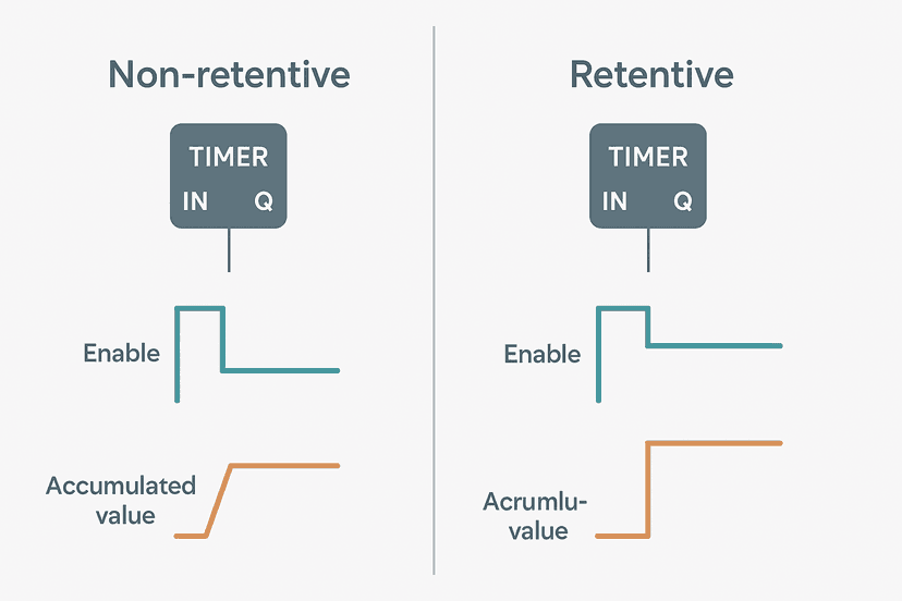
Retentive vs Non-Retentive PLC Timers: Key Differences
Retentive and non-retentive PLC timers behave completely differently when the enable bit drops. Learn which to use, how each resets, and see real ladder examples across platforms.
Aug 2, 2026 · 8 min read
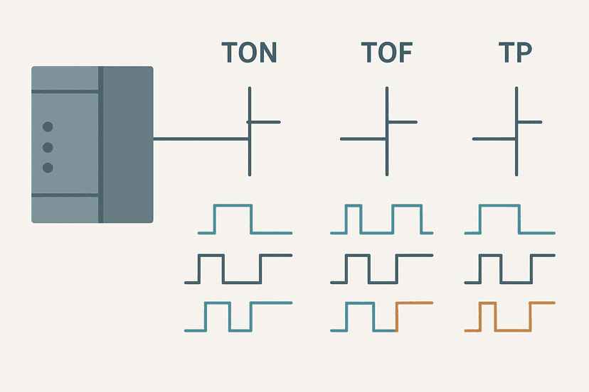
PLC Timer Ladder Logic: 5 Practical Examples
Five practical PLC timer ladder logic examples covering TON, TOF and TP instructions, with timing diagrams, gotchas and field-tested advice for Rockwell and generic platforms.
Aug 1, 2026 · 8 min read
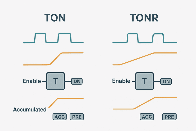
Retentive Timer in PLC Ladder Logic Explained
A retentive timer keeps its accumulated value when power is lost or the rung goes false. Learn how TONR works, when to use it, and see real ladder examples.
Aug 1, 2026 · 9 min read
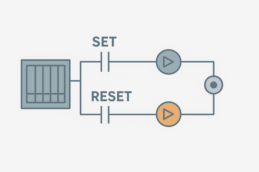
Set-Reset Flip-Flop in Ladder Logic: Full Guide
Learn how the set-reset flip-flop works in PLC ladder logic, how it differs from a seal-in rung, and when each pattern belongs in your program.
Aug 1, 2026 · 8 min read
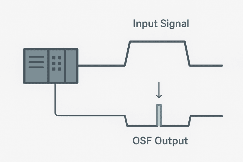
Falling-Edge One-Shot in Ladder Logic: OSF Explained
The OSF instruction fires a single scan pulse on a signal's falling edge. Learn exactly how it differs from OSR, where it saves you from logic bugs, and see a real worked example.
Jul 31, 2026 · 8 min read
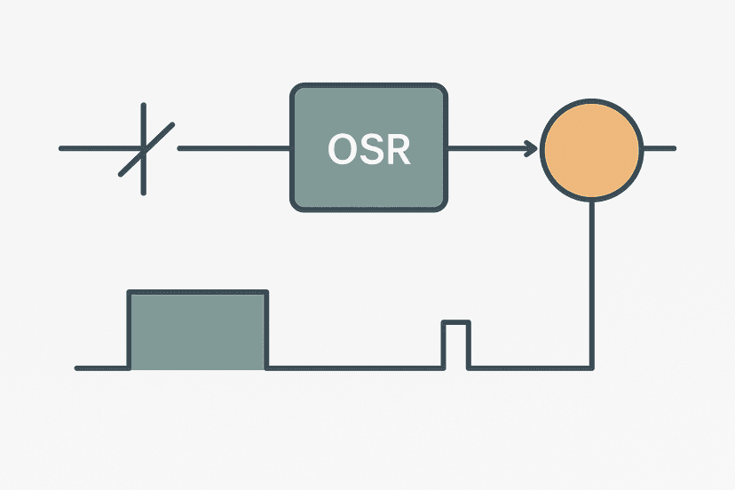
One-Shot Rising Edge in Ladder Logic: OSR Explained
Learn how the OSR (one-shot rising) instruction works in PLC ladder logic, when to use it, and how to avoid the single-scan pitfall that catches every newcomer.
Jul 31, 2026 · 8 min read
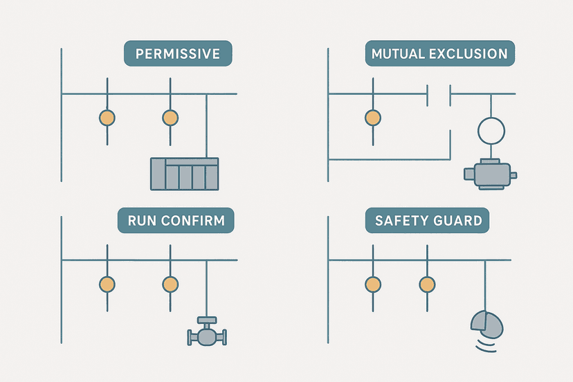
Ladder Logic Interlocks: How They Work and Why
Ladder logic interlocks stop dangerous or invalid machine states before they happen. Learn the four core interlock patterns, see real rung examples, and avoid the wiring gotchas that bite engineers on commissioning day.
Jul 31, 2026 · 8 min read
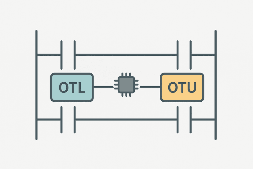
OTL and OTU Latch Coils in Ladder Logic Explained
OTL and OTU latch coils hold state through a power cycle. Learn how they work in ladder logic, how they differ from seal-in rungs, and when each belongs in your program.
Jul 30, 2026 · 8 min read
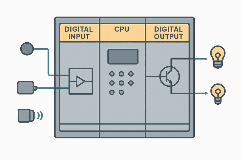
How PLC Input and Output Modules Work
PLC input and output modules are more than just terminal strips. Learn exactly how signals get conditioned, isolated, and mapped into CPU memory on every scan.
Jul 30, 2026 · 9 min read
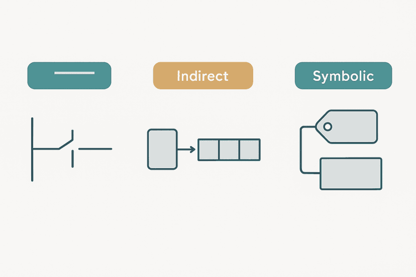
PLC Addressing Modes: Direct, Indirect and Symbolic
Direct, indirect and symbolic addressing each work differently inside a PLC. This guide breaks down how each mode works, when to use it, and the gotchas that catch engineers off guard.
Jul 30, 2026 · 9 min read
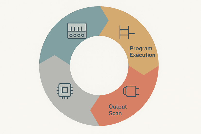
How the PLC Scan Cycle Works: Step by Step
The PLC scan cycle is the heartbeat of every control system. Learn exactly what happens during input scan, program execution, and output scan, with real numbers and field gotchas.
Jul 29, 2026 · 10 min read
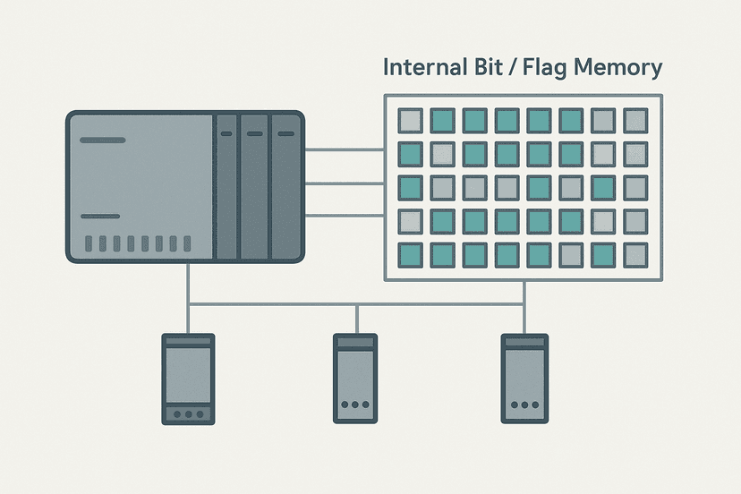
PLC Internal Bits: Flags, Coils and How to Use Them
Internal bits, flags and internal coils let your PLC logic communicate with itself across rungs. Learn what they are, how to use them correctly, and the gotchas that trap beginners.
Jul 29, 2026 · 9 min read
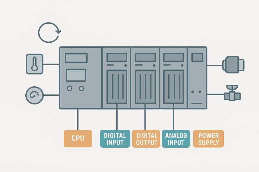
What Is a PLC Controller and How Does It Work?
Learn what a PLC controller is, how it executes logic in a repeating scan cycle, and how inputs, outputs, and memory work together to control real machines.
Jul 29, 2026 · 8 min read
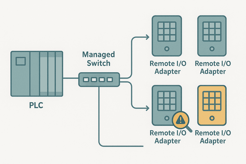
EtherNet/IP Communication Loss: How to Diagnose It
EtherNet/IP communication loss can halt a whole production line in seconds. This guide walks through every layer of the fault, from cable to CIP timeout settings, with real diagnostic steps.
Jul 28, 2026 · 10 min read
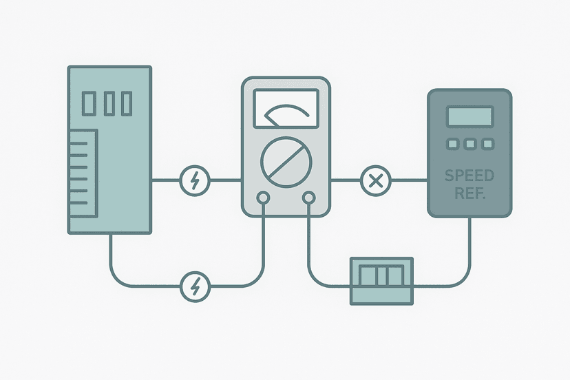
PLC Analog Output Faults: How to Diagnose Them
Analog output faults are sneaky: the PLC logic looks fine but nothing moves. Learn how to isolate 4-20 mA and 0-10 V AO faults in under 20 minutes.
Jul 28, 2026 · 9 min read
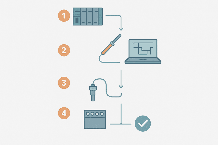
PLC Fault Finding: A Systematic 6-Step Method
Learn a systematic 6-step PLC fault finding method: gather clues, isolate the fault layer, use online monitoring, test I/O, and verify the fix. Real field examples included.
Jul 28, 2026 · 7 min read
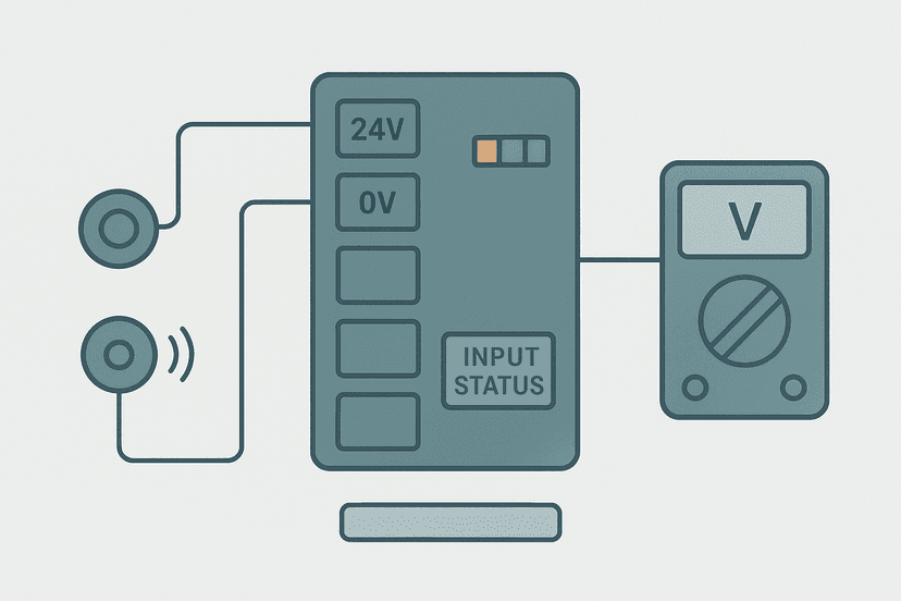
PLC Digital Input Faults: How to Diagnose Them
PLC digital input faults are deceptive. The status bit looks fine but the machine misbehaves. Here is how to systematically find the real cause in minutes.
Jul 27, 2026 · 9 min read
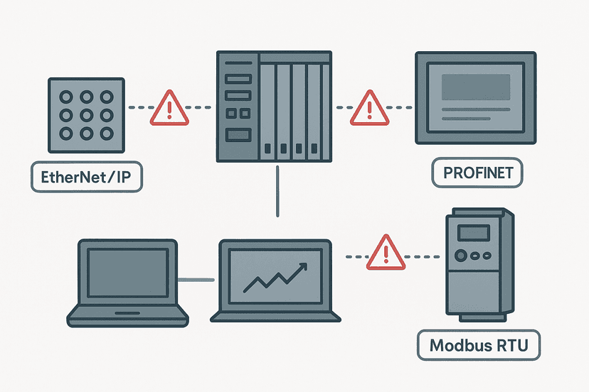
PLC Communication Faults: How to Diagnose Them
PLC communication faults kill production fast. This guide walks you through diagnosing lost connections between PLCs, HMIs, remote I/O and drives with real steps and field-tested methods.
Jul 27, 2026 · 9 min read
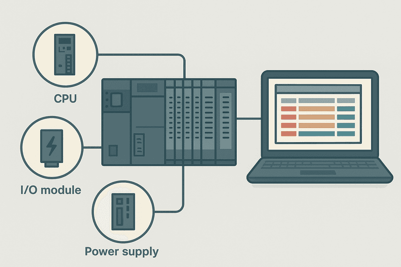
Mitsubishi PLC Error Codes: How to Read and Fix Them
Mitsubishi MELSEC PLCs log specific error codes when something goes wrong. This guide explains how to read them in GX Works3, what the most common codes mean, and how to fix each one.
Jul 27, 2026 · 9 min read
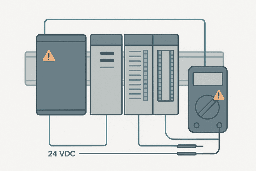
PLC Power Supply Faults: How to Diagnose Them
PLC power supply faults are among the most misdiagnosed problems in industrial automation. Learn exactly how to test, isolate and fix them with a multimeter and a clear method.
Jul 26, 2026 · 10 min read
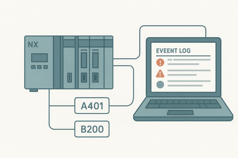
Omron PLC Error Codes: How to Read and Fix Them
Omron PLC error codes explained: what each severity level means, where to find the details in Sysmac Studio and CX-Programmer, and how to clear them safely.
Jul 26, 2026 · 8 min read
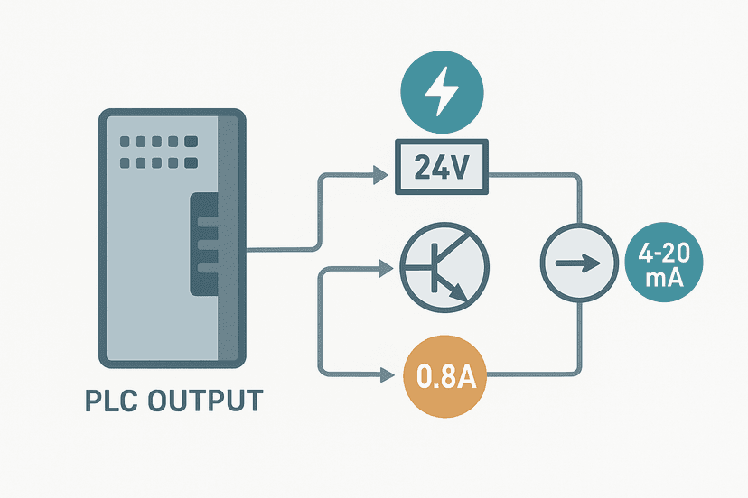
PLC Output Faults: How to Diagnose Them Fast
PLC output faults stop machines cold. Learn how to diagnose relay, transistor and analog output failures fast using the right tools and a proven sequence.
Jul 26, 2026 · 9 min read
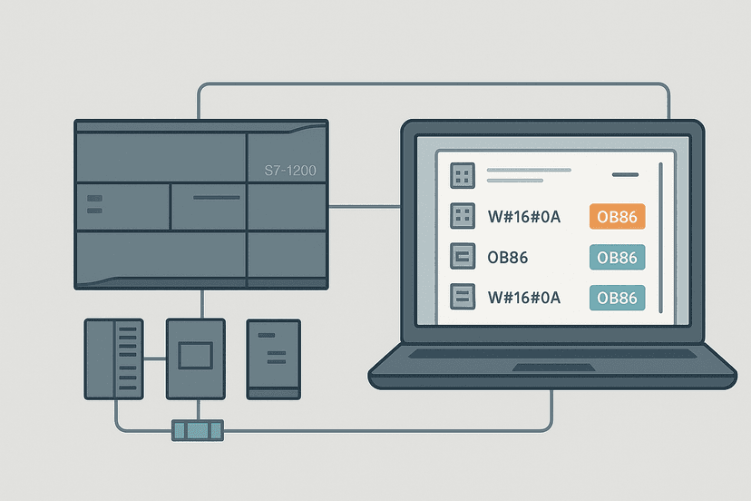
Siemens PLC Error Codes: How to Read and Fix Them
Siemens PLC error codes tell you exactly what went wrong if you know where to look. This guide covers diagnostic buffers, OBs, and fixes for the most common faults.
Jul 25, 2026 · 8 min read
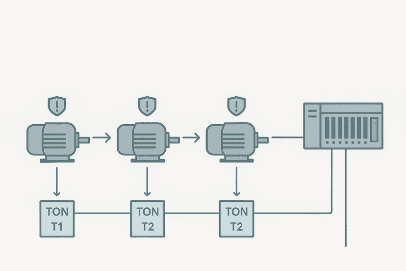
3-Motor Start Sequence PLC Exercise: Ladder Logic
Learn how to write a 3-motor timed start sequence in PLC ladder logic. Full rungs, tag names, fault handling and a worked Rockwell example included.
Jul 25, 2026 · 8 min read